
Related Manuals for Hioki 3455


Summary of Contents for Hioki 3455
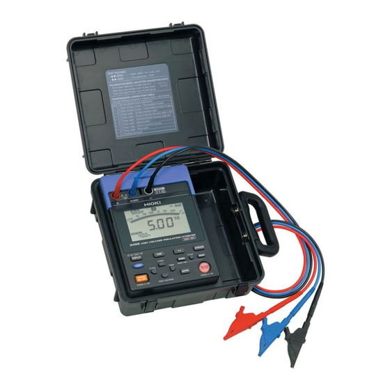
- Page 1 Instruction Manual 3455 HIGH VOLTAGE INSULATION HiTESTER February 2013 Revised edition 10 3455A981-10 13-02H...
-
Page 3: Table Of Contents
Contents Introduction ............1 Verifying Package Contents / Open the case .. 1 Safety Information ........... 5 Operating Precautions ........8 1 Overview Product Overview ......... 13 Features ..........15 Measurement Overview ....... 17 Names and Functions of Parts ..... 24 Screen Setup ........ - Page 4 3.2.1 Starting Measurement ......58 3.2.2 Ending Measurement ......64 3.2.3 Checking and Deleting Held Data ..66 3.2.4 Automatic Discharge Function ....67 3.2.5 Switching to Leakage Current Indication ..........68 3.2.6 Insulation Resistance Measurement Basis ...........69 3.2.7 Use of GUARD Terminal .....71 Measuring Voltage .......73 Measuring Temperature .......76 3.4.1 Measurement Procedure ....76 4 Advanced Measurement...
- Page 5 6.3.2 Clearing Indications of Temperature and Humidity Stored Data ....133 Communicating with PC ..... 134 6.4.1 Installing Data Analysis Software for 3455 ..........135 6.4.2 Installing Driver ......... 136 6.4.3 Downloading Data to Save to PC/ Setting up Tester on PC ....137 7 Specifications General Specifications .......
- Page 6 9750-01, -02,- 03, -11, -12, -13 TEST LEADs and 9751-01, -02, -03 ALLIGATOR CLIPs Specifications ..150 8 Maintenance and Service Troubleshooting .........152 Cleaning ..........154 Error Display ........154 Performing System Reset ....156 Discarding the Instrument ....157 Appendix Appendix 1Test Voltage Characteristic Graph ..........161 Appendix 2Example of Insulation Resistance Criteria ..........162...
-
Page 7: Introduction
Introduction Introduction Thank you for purchasing the HIOKI Model 3455 HIGH VOLTAGE INSULATION HiT- ESTER. To obtain maximum performance from the instrument, please read this man- ual first, and keep it handy for future refer- ence. Registered trade mark • Windows and Internet Explorer are regis- tered trademark of Microsoft Corporation in the United States and/or other countries. - Page 8 Verifying Package Contents / Open the case Procedure Draw the latch outwards with your fin- ger. While raising the entire latch, place a finger on the top of the latch and pull it out.
- Page 9 Verifying Package Contents / Open the case Main Unit 3455 HIGH VOLTAGE INSULATION HiTESTER 1 Accessories 9750-01,-02,-03 TEST LEAD (Red, Black, Blue) Lead length Approx. 3 m 1 each 9751-01,-02,-03 ALLIGATOR CLIP(Red, Black, Blue) 1 each Instruction Manual LR6 alkaline battery 6...
- Page 10 Verifying Package Contents / Open the case Options 9750-11,-12,-13 TEST LEAD (Red, Black, Blue Lead length Approx. 10 m) The specifications for the 9750-11 and 9750-12 models differ from the standard specifications in regards to temperature characteristics. See 7.2"Measurement Specifications" (page 144).
-
Page 11: Safety Information
Safety Information Safety Information This instruments designed to comply with IEC 61010 Safety Standards, and has been thoroughly tested for safety prior to shipment. However, mishandling during use could result in injury or death, as well as damage to the instrument. However, using the instrument in a way not described in this manual may negate the provided safety features. - Page 12 Safety Information The following symbols in this manual indi- cate the relative importance of cautions and warnings. Indicates that incorrect operation presents an extreme hazard that could result in serious injury or death to the user. Indicates that incorrect operation presents a significant hazard that could result in serious injury or death to the user.
- Page 13 Safety Information Measurement categories This instrument and 9750-01, -02, -03, -11, -12, -13 TEST LEAD comply with CAT IV (600 V), CAT III (1000 V) safety requirements. To ensure safe operation of measurement instruments, IEC 61010 establishes safety standards for various electrical environments, categorized as CAT to CAT IV, and called measurement categories.
-
Page 14: Operating Precautions
If you find any damage, contact your dealer or Hioki representative. Before using the instrument, make sure that the insulation on the test leads and... - Page 15 Operating Precautions Placement • Operating temperature and humidity: 0 to 40°C (32 to 104°F) 90%RH or less (no condensation) • Temperature and humidity range for guaran- teed accuracy: Insulation resistance measurement / leak- age current measurement 0 to 28°C (32 to 82°F) 90%RH or less (no condensation) Voltage measurement / temperature mea- surement...
- Page 16 Operating Precautions Observe the following to avoid electric shock and short circuits. • Before connecting or disconnecting the test leads to/from the tester, be sure to disconnect the test leads from the object under test and turn off power. • Do not perform measurement with the battery cover removed •...
- Page 17 Operating Precautions • This instrument is designed for use indoors. operated temperatures between 0 and 40°C (32 and 104°F) without degrading safety. • To avoid damage to the instrument, protect it from physical shock when transporting and handling. Be especially careful to avoid physical shock from dropping.
- Page 18 Never use abrasives or solvent cleaners. • Hioki shall not be held liable for any problems with a computer system that arises from the use of this CD-R, or for any problem related...
-
Page 19: Overview
1.1 Product Overview Overview 1.1 Product Overview The 3455 is an insulation resistance tester with a wide measurement range, for use in such environments involving low to high voltage. The tester has the functions and purposes given below. Reference Function... - Page 20 1.1 Product Overview Reference Function Purpose page Step voltage To determine whether the insula- 4.4 (P.93) test tion resistance of an object chang- es according to test voltage applied. Memory To save the measurement data. 5 (P.101) To create tables or graphs of the 6.4 (P.134) Communica-...
-
Page 21: Features
1.2 Features 1.2 Features Wide test voltage range Generates a wide range of test voltages, from 250 V to 5 kV The voltage may be chosen from the com- monly used presets of 250 V, 500 V, 1 kV, 2.5 kV, and 5 kV;... - Page 22 1.2 Features Compact hard case The case is durable-designed to withstand the toughest of working conditions, com- pact, and highly portable. Dual battery power supply The tester may be powered by either alka- line or rechargeable nickel-hydrogen batter- ies. (Selectable via switch) ...
-
Page 23: Measurement Overview
Measurement condition When measuring insulation resistance, ensure that power supply to the object under test is turned off. Performing Measurement • 3455 HIGH VOLTAGE INSULATION HiT- ESTER • LR6 alkaline battery, or 9459 BATTERY PACK • 9750-01,-02,-03 TEST LEAD • 9751-01,-02,-03 ALLIGATOR CLIP •... - Page 24 1.3 Measurement Overview Flow of measurement Prepare for measurement 2 "Measurement Preparations" (page 31) Before starting measurement, check the fol- lowing: • The power supply method. • The power ON/OFF method. • That date and time are set. •...
- Page 25 1.3 Measurement Overview Connect the test leads into the 2.4 (page 50) "+" and "-" terminals of the tester 3.2.1 (page 58) and to the object to be tested. Warning: Confirm that the power supply to the object under test has been turned off. Object to be measured (Ex.: Motor) Test lead (Black) Test lead (Red)
- Page 26 1.3 Measurement Overview Press the key to gener- 3.2.1 (page 58) ate a voltage and start measure- ment. Read the indication. 3.2.1 (page 58) Press the key to stop 3.2.2 (page 64) voltage generation and measure- ment. The automatic discharge function ...
- Page 27 1.3 Measurement Overview Voltage Measurement 3.3 "Measuring Voltage" (page 73) Connect the test leads into the "+" and "-" termi- nals of the tester and to the object to be tested. Test lead (Red) Test lead (Black) + terminal GUARD terminal - terminal...
- Page 28 1.3 Measurement Overview Temperature Measurement 3.4 "Measuring Temperature" (page 76) Insert the temperature sensor into the tempera- ture sensor terminal of the tester. Read the indication. Press the key to stop temperature mea- surement.
- Page 29 1.3 Measurement Overview Record measurement data 5 "Recording Measurement Data (Memory Function)" Insulation resistance and temperature mea- surement data are held after measurement is completed. This data will be cleared if power is turned off. To store the data, use the memory func- tion.
-
Page 30: Names And Functions Of Parts
1.4 Names and Functions of Parts 1.4 Names and Functions of Parts Front Slide the shutter. Operating panel (page 26) - Page 31 1.4 Names and Functions of Parts Name Function Connect the AC adapter to this terminal. AC adapter 2.1.3 "Connecting the AC Adapter" (page terminal Connect the USB Cable to this terminal. USB terminal 6.4.3 "Downloading Data to Save to PC/ Setting up Tester on PC"...
- Page 32 1.4 Names and Functions of Parts Operating panel Function Used to turn power on/off. Used to set parameters. Used to toggle between set voltage and monitor voltage after resistance measurement. Used to set parameters. Used to set test voltage. • Used to make fine adjustments to test voltage. •...
- Page 33 1.4 Names and Functions of Parts Function • Used to start and stop of resistance measure- ment. • Blinks when a voltage is generated. • Blinks when a voltage of 50 V or more is input (Warning lamp) or when discharging is performed. •...
-
Page 34: Screen Setup
1.5 Screen Setup 1.5 Screen Setup All On Measuring Voltage Blinking Measured voltage 3.3 "Measuring Voltage" (page 73) Measuring Temperature 3.4 "Measuring Temperature" (page 76) -
Page 35: Measuring Insulation Resistance
1.5 Screen Setup Measuring Insulation Resistance Blinking Actual output voltage > blinks if the input exceeds the measure- ment range. Elapsed time Insulation resistance 3.2 "Measuring Insulation Resistance" (page 56) The screen is switched over with the key. Leakage Current Display Blinking Actual output voltage... - Page 36 1.5 Screen Setup...
-
Page 37: Measurement Preparations
2.1 Supplying Power Measurement Preparations 2.1 Supplying Power This tester may be powered by several means. • LR6 alkaline battery See 2.1.1 "Installing or Replacing the Battery" (page 31). • 9459 BATTERY PACK (Option) See 2.1.2 "Installing the Battery Pack (Rechargeable nickel-hydrogen battery)"... - Page 38 2.1 Supplying Power • When the battery status indicator is low, replace the batteries. • Use the specified batteries only. Do not use manganese batteries, for example, since operating time will be greatly reduced. • To avoid corrosion from battery leakage, remove the batteries from the instrument if it is to be stored for a long time.
- Page 39 2.1 Supplying Power Place six LR6 alkaline batteries into the battery compartment. (Replace all six at the same time) Turn the battery selector switch to LR6. When the power is turned on, “ ” appears on the top left of the screen. ...
-
Page 40: Installing The Battery Pack (Rechargeable Nickel-Hydrogen Battery)
Charging Procedure See 2.1.4 "Charging the Battery Pack" (page 41). • For battery operation, use only the HIOKI Model 9459 BATTERY PACK. We cannot accept responsibility for acci- dents or damage related to the use of any other batteries. • To avoid heat buildup, rupture, or leak-... - Page 41 2.1 Supplying Power • If the battery pack is not used for an extended period of time, remove it from the tester and store at a temperature between -20 to 30°C, to prevent deterioration. • Charge the battery at least every 2 months.
- Page 42 2.1 Supplying Power Connect the battery pack to the tester. (Align the protrusions.) Place the battery pack in the battery pack compartment. Turn the battery selector switch to 9459. When the power is turned on, “ ” appears on the top left of the screen. See 2.2 "Turning Power On and Off"...
- Page 43 2.1 Supplying Power Replacement Tools: Phillips screwdriver Procedure Turn off power and disconnect the test leads, AC adapter, and USB cable from the tester. See 2.2 "Turning Power On and Off" (page 44). Loosen the set screw on the rear of the tester and remove the battery cover.
- Page 44 2.1 Supplying Power Connect the new battery pack to the tester. (Align the protrusions.) Place the battery pack in the battery pack compartment. Turn the battery selector switch to 9459. When the power is turned on, “ ” appears on the top left of the screen. See 2.2 "Turning Power On and Off"...
-
Page 45: Connecting The Ac Adapter
2.1 Supplying Power 2.1.3 Connecting the AC Adapter • Optional 9753 AC ADAPTER can be used. • When the AC adapter is connected to the tester, you can charge the battery pack, communicate with a PC, perform temper- ature measurement, and edit the settings. However, you cannot measure insulation resistance, leakage current or voltage. - Page 46 2.1 Supplying Power Procedure 2 Move the shutter. Insert the power cord into the AC adapter. Move the shutter of the tester to reveal the AC adapter terminal. Insert the output cable of the AC adapter into the AC adapter terminal. Make sure that the commercial power source voltage matches the rated supply voltage of the AC adapter.
-
Page 47: Charging The Battery Pack
2.1 Supplying Power Charging the Battery Pack 2.1.4 The 9459 BATTERY PACK can be charged while installed in the tester, using the optional 9753 AC ADAPTER. Short charge time: Approx. 3 hours (at 23°C room temperature) • Carry out battery charging at an ambient temperature between 10°C and 40°C. - Page 48 2.1 Supplying Power Procedure Install the battery pack. See 2.1.2 "Installing the Battery Pack (Rechargeable nickel-hydrogen battery)" (page 34). Move the shutter to reveal the AC adapter terminal. Move the shutter. Connect the AC adapter to the AC adapter terminal. Rapid charging begins.
- Page 49 2.1 Supplying Power If the AC adapter is connected to the tester when the tester is off, the tester is automatically turned on and rapid charging begins. When rapid charging is completed, the battery status indictor changes from blinking to continuously lit. After rapid charging finishes, the battery is trickle- charged (maintained in a fully-charged state).
-
Page 50: Turning Power On And Off
2.2 Turning Power On and Off 2.2 Turning Power On and Off Turning power On Press and hold the key for around one second. After all the screen indications light, the version and the position of the battery selector switch appear and then the tester enters the standby state. -
Page 51: Auto Power Off
2.2 Turning Power On and Off 2.2.1 Auto Power Off • Power is automatically turned off around 10 minutes after the last operation. This function, however, is not available during insulation resistance measurement. • [ ] will start blinking around 30 sec- onds before power is turned off. -
Page 52: Setting And Checking Date And Time
2.3 Setting and Checking Date and Time 2.3 Setting and Checking Date and Time Set the time and date before use of the tester. Use the Christian calendar. 2.3.1 Setting Date and Time Procedure When the tester is in a standby state, press key. - Page 53 2.3 Setting and Checking Date and Time Pressing moves the blinking cursor. Place the cursor at the digit, value, etc., you wish to change. Year, month, day, hour, and minutes can be changed. The year-month-day screen and the hour- minute-second screen are switched to and from each other in the procedure below.
- Page 54 • The date and time can be set on a PC using the data analysis software for model 3455. • The data analysis software for model 3455 must be installed on the PC. Details See 6.4 "Communicating with PC" (page 134).
-
Page 55: Checking Date And Time
2.3 Setting and Checking Date and Time 2.3.2 Checking Date and Time Procedure When the tester is in the standby state, press the key. Year, month, and day appear. Press the key. Hours, minutes, and seconds appear. Pressing key returns to the standby screen. -
Page 56: Connecting Test Lead
2.4 Connecting Test Lead 2.4 Connecting Test Lead • To avoid electric shock, be sure to dis- connect the test leads from the object under test and turn off power, before connecting or disconnecting the test leads to/from the tester. •... - Page 57 2.4 Connecting Test Lead Connect the red test lead to the + terminal and the black test lead to the - terminal. For insulation resistance measurement, connect the blue test lead to the GUARD terminal if necessary. Check that the test leads are fully inserted.
-
Page 58: Connecting Temperature Sensor
2.5 Connecting Temperature Sensor 2.5 Connecting Temperature Sensor Temperature sensors may be damaged by high voltage or static electricity. Do not expose the temperature sensor to excessive impact, or allow the cable to be bent, since malfunction or faulty connection may result. Temperature sensors cannot be used simultaneously with test leads. -
Page 59: Measurement
Using the product in such conditions could cause an electric shock, so contact your dealer or Hioki representative for replacements. Make sure the terminals are clean and dry. Wipe with a dry cloth to remove any moisture, since measurement errors may result if moisture is present. - Page 60 3.1 Pre-Operation Inspection Inspection Procedure Clip the resistor to the red and black test leads connected to the tester. Also, clip the resistor to the test lead of the high-voltage meter. Set the test voltage of the tester to [5.00 kV].
- Page 61 3.1 Pre-Operation Inspection Check to see if the insulation resistance reading of the tester is 20 M. Voltage Insulation resistance Stop insulation resistance measurement. See 3.2.2 "Ending Measurement" (page 64). Short-circuit the tips of the clips of the red and black test leads of the tester. Press the key to see if the test volt- age setting is...
-
Page 62: Measuring Insulation Resistance
3.2 Measuring Insulation Resistance 3.2 Measuring Insulation Resistance Observe the following to avoid electric shock and short circuits. A. Do not use the tester if the shutter is broken. Shutter B. Check Table 1 before connecting test leads to the tester. C. - Page 63 3.2 Measuring Insulation Resistance • When measuring insulation resistance, dangerous voltage is applied to the measurement terminals. To avoid elec- tric shock, do not touch the terminals and test leads. • Do not touch the object under test or disconnect the test leads after measure- ment has been completed until the auto- matic discharge function is completed.
-
Page 64: Starting Measurement
3.2 Measuring Insulation Resistance 3.2.1 Starting Measurement Procedure Connect the alligator clip to the end of each test lead. Insert it fully. Move the shutter to reveal the + and - terminals. - Page 65 3.2 Measuring Insulation Resistance Connect the red test lead to the + terminal and the black test lead to the - terminal. Connect the blue test lead to the GUARD terminal if necessary. Fully insert the test leads. See 3.2.7 "Use of GUARD Terminal" (page 71). Warning: Confirm that the power supply to the object under test has been turned off.
- Page 66 3.2 Measuring Insulation Resistance Press the key, after which the voltage display starts blinking. The test voltage is chosen from 250 V, 500 V, 1.00 kV, 2.50 kV, and 5.00 kV using the keys. Pressing keys, you can make fine adjustment of the test voltage setting. For step voltage testing, hold down the key, which will display [...
- Page 67 3.2 Measuring Insulation Resistance Hold down the key for more than one second. A voltage is generated and measurement begins. mark and key lamp starts blinking. Blinking Actual output voltage >blinks if the input exceeds the measurement range. Elapsed time Insulation resistance >...
- Page 68 3.2 Measuring Insulation Resistance Read the indication. • If the indication is unstable, press the key. The average of the measurements is shown. • Resistance indication is switched to leakage current indication by pressing the key. See 3.2.5 "Switching to Leakage Current Indication" (page 68).
- Page 69 3.2 Measuring Insulation Resistance The state not to be started the measure- ment When the display reflects the following state, insulation resistance measurement cannot be started. • The setting value is blinking to indicate that the instrument being set up •...
-
Page 70: Ending Measurement
3.2 Measuring Insulation Resistance 3.2.2 Ending Measurement Procedure Press the key with the test leads connected to the object under test. The last measurement is held. lights up.) Immediately after measurement has been completed, the discharge circuit in the tester automatically discharges the electric charge remaining in the object under test. - Page 71 3.2 Measuring Insulation Resistance When the voltage falls to about 10 V, the tester stops discharging and the mark key lamp are turned off. Actual output voltage (last measurement) Elapsed time of the Last end of measurement measurement value • If the key is pressed during measurement, automatic discharge is performed before power is turned off.
-
Page 72: Checking And Deleting Held Data
3.2 Measuring Insulation Resistance 3.2.3 Checking and Deleting Held Data Checking Held Data The following data are held and displayed after insulation resistance measurement has been completed. • Insulation resistance (digital value and bar graph) • Test voltage • Actual output voltage •... -
Page 73: Automatic Discharge Function
3.2 Measuring Insulation Resistance 3.2.4 Automatic Discharge Function • When insulation resistance with a capaci- tance component is measured, this com- ponent remains charged with a high- voltage equivalent to the test voltage, which is dangerous. • This tester automatically discharges remaining electric charge using the inter- nal circuit after measurement. -
Page 74: Switching To Leakage Current Indication
3.2 Measuring Insulation Resistance 3.2.5 Switching to Leakage Current Indi- cation Insulation resistance indication may be switched to leakage current indication. During measurement Blinking Actual output voltage The bar graph shows the resistance measurement. < blinks at below 1 nA. Elapsed time Current measurement Before measuring insulation resistance... -
Page 75: Insulation Resistance Measurement Basis
3.2 Measuring Insulation Resistance Holding data after measurement Every time key is pressed, the indi- cation changes in the order: resistance current DAR 1 min/15s DAR 1 min/30s resistance current etc. PI/DAR See 4.2 "Displaying PI and DAR" ... - Page 76 3.2 Measuring Insulation Resistance Reproducibility of insulation resistance measurement When measuring the same object repeat- edly, the insulation resistance and leakage current indications may differ. This is caused by polarization*, which occurs when a volt- age is applied to an insulating material. An insulating material is represented by an equivalent circuit as shown by the diagram on the previous page.
-
Page 77: Use Of Guard Terminal
3.2 Measuring Insulation Resistance 3.2.7 Use of GUARD Terminal Measurement unaffected by surface electrical resistance A GUARD terminal is used to prevent the surface electrical resistance of an insulating material affecting measurement, enabling correct measurement of the entire volume of the material. - Page 78 3.2 Measuring Insulation Resistance Measurement using G (GUARD) terminal grounding G terminal grounding is used for measuring the insulation resistance between the core and the metallic shielding layer of a high- voltage cable with the cable connected to other high-voltage equipment. The diagram below shows an example of measurement.
-
Page 79: Measuring Voltage
3.3 Measuring Voltage 3.3 Measuring Voltage The tester measures the voltage of an exter- nal circuit, e.g., commercial power supply. AC and DC are distinguished automatically. To prevent damage to the tester and per- sonal injury, observe the precautions below. •... - Page 80 3.3 Measuring Voltage Procedure Connect alligator clips to the ends of test leads. Insert it fully. Move the shutter to reveal the + and - terminals. Connect the red test lead to the + termi- nal and the black test lead to the - termi- nal.
- Page 81 3.3 Measuring Voltage Clip the ends of the test leads to the cir- cuit to be tested. When the voltage exceeds 50 V, the mark and key lamp blink. Read the voltage indication. key is not used. Blinking Measured voltage...
-
Page 82: Measuring Temperature
3.4 Measuring Temperature 3.4 Measuring Temperature 3.4.1 Measurement Procedure Do not attempt to measure the tempera- ture of objects carrying a voltage. Doing so will result in a short-circuit accident or an electrocution accident. Temperature sensors may be damaged by high voltage or static electricity. - Page 83 3.4 Measuring Temperature Temperature measurement begins auto- matically. Read the temperature indication. Press key or disconnect the tem- perature sensor to stop measurement. lights up and the last mea- surement is held. After measuring temperature (When the resistance is not measured.) ...
- Page 84 3.4 Measuring Temperature • If temperature measurement is stopped using the key, measurement may be resumed by pressing key. • When an insulation resistance measurement is held, if the temperature sensor is disconnected, the tempera- ture indication switches to the elapsed time indication at the time of insulation resistance measurement.
-
Page 85: Advanced Measurement
4.1 Using Timer Advanced Measurement 4.1 Using Timer Used to set the tester to automati- What is it used for? cally stop at a specified time. If the timer is set during insulation resis- tance measurement, the measurement automatically ends at the set time. Selectable time: 30 sec. - Page 86 4.1 Using Timer Press the key to confirm the entry. If the key is pressed without pressing key, the tester returns to a standby state with the time unchanged. When the timer is successfully set, the [TIMER] indicator lights. Holding down the key for longer than one second generates a test voltage, and measurement begins.
- Page 87 4.1 Using Timer Timer not used Procedure When the tester is in a standby state, press the key. The time indication will blink. Press the key to select - - min - - s. - - min - - s is also selected by pressing key.
- Page 88 4.1 Using Timer Checking set time Procedure When the tester is in a standby state, press the key. The currently set time blinks. Check the time. Press the key to return to the previous screen.
-
Page 89: Displaying Pi And Dar
4.2 Displaying PI and DAR 4.2 Displaying PI and DAR Used to check whether insulation re- sistance increases with time after a voltage is applied. What is it used for? (When the PI value or the DAR val- ue is close to 1, the tester deter- mines that the insulation of the object under test is deteriorated.) •... - Page 90 4.2 Displaying PI and DAR Measure insulation resistance. To determine PI, continue measurement for 10 minutes (for a default time setting). To determine DAR, continue measurement for one minute. Stop measurement. Press the key several times to display PI, DAR 1 min/15 s, or DAR 1 min/30 s.
- Page 91 4.2 Displaying PI and DAR Measurement Interval Right: 1st Left : 2nd Resistance Right: 1st measurement Left : 2nd measurement Measurement Interval 1st : 1 min. 2nd : 10 min. Resistance Right : 1st 30 G Left : 2nd 60 G Substitute into the formula;...
- Page 92 4.2 Displaying PI and DAR Blinking resistance indication on PI or DAR display screen When the resistance indication blinks, the displayed reading may be incorrect. (Insu- lation resistance changed rapidly before end of set specified time, affecting mea- surement range due to internal circuit fail- ure to respond) When the resistance reading blinks, regard the PI or DAR value as a reference.
-
Page 93: Temperature Correction (Tc)
4.3 Temperature Correction (TC) 4.3 Temperature Correction (TC) Used to acquire insulation resis- tance at a temperature differing from What is it used for? the actual temperature at which measurement is performed. • The tester converts measured resistance to the resistance at a reference tempera- ture and displays the result. -
Page 94: Performing Temperature Correction
4.3 Temperature Correction (TC) 4.3.1 Performing Temperature Correction Procedure Measure temperature and insulation resistance. The measurements are held upon completion. (Either may be measured first.) 3.2 "Measuring Insulation Resistance" (page 56) See 3.4 "Measuring Temperature" (page 76). The temperature may also be entered with keys. - Page 95 4.3 Temperature Correction (TC) Press the key to confirm the choice of table No. The reference temperature blinks. Adjust the reference temperature using key. If the keys are held down simultaneously, the reference tempera- ture is returned to its default. (40°C for table 9 and 20°C for the rest.)
- Page 96 4.3 Temperature Correction (TC) Press the key to confirm the ref- erence temperature. [TC] lights up and the tester enters tem- perature correction mode. The LCD displays the resistance at the reference temperature converted from the measurement. Bar graph (Value before correction) Digital value (Value after...
- Page 97 4.3 Temperature Correction (TC) • If resistance before correction exceeds the measurement range, it cannot be converted and the LCD displays [ - - - • After the tester is placed in temperature correction mode, measurement or input of temperature measurement insulation resistance may be conducted.
-
Page 98: Exiting Temperature Correction Mode
4.3 Temperature Correction (TC) 4.3.2 Exiting Temperature Correction Mode Press the key. Procedure [TC] is turned off and the tester exits temperature correction mode. -
Page 99: Step Voltage Test
4.4 Step Voltage Test 4.4 Step Voltage Test Used to determine the effect of the What is it used for? test voltage level on insulation resis- tance of an object. What is a step voltage test? • The tester increases the test voltage gradually and monitors the resultant insu- lation resistance and leakage current. -
Page 100: Setting And Conducting A Step Voltage Test
4.4 Step Voltage Test When 5 minutes has passed in total, measurement automatically stops. STEP5.00 kV Measurement Measurement End of 5 kV Measurement Measurement 4 kV Measurement 3 kV Measurement 2 kV 1 kV 1 min. 2 min. 3 min. 4 min. 5 min. •... - Page 101 4.4 Step Voltage Test Press the key. The voltage indication will stop blinking and the tester enters the step voltage test mode. Lighting Interval for 1 step To start the step voltage test, hold down the key for more than one second. mark and the start blinking, and insulation resistance or leakage current appears on the...
- Page 102 4.4 Step Voltage Test The test voltage rises at regular intervals and the test stops automatically. The last data is held and displayed. lights up.) Actual output voltage Last resistance Elapsed time at completion measurement • While [ ] is on (temperature correction mode), STEP cannot be selected.
-
Page 103: Viewing Detailed Data Of Each Step After Step Voltage Test
4.4 Step Voltage Test 4.4.2 Viewing Detailed Data of Each Step after Step Voltage Test Procedure When the tester is in standby state after step voltage test, press the key. will blink and the LCD displays the details of the step voltage test data. The first page shows the data at the test voltage for step 1. - Page 104 4.4 Step Voltage Test To display other detailed data, use the following keys. Indications to be switched Keys used Voltages and data at 5 steps Insulation resistance leakage current Temperature/ Elapsed time to the Humidity step currently displayed (Temperature and humidity are measured imme- diately before or after the test.) Test voltage (setting) and actual output voltage are toggled automatically.
-
Page 105: Exiting Step Voltage Test Mode
4.4 Step Voltage Test 4.4.3 Exiting Step Voltage Test Mode Procedure Press the key in standby state, and the voltage indication will blink. To turn off the [STEP] indicator, press key several times. Press the key. The voltage indication changes from blinking to constantly lit. - Page 106 4.4 Step Voltage Test...
-
Page 107: Recording Measurement Data (Memory Function)
Recording Measurement Data (Memory Function) The tester stores measurement data, settings, date and time in the internal memory. Data is not erased when the power is shut off. There are two recording methods. (Combinable) Manual Stores held data recording: Logging Stores insulation resistance data at regular intervals. - Page 108 • The table below shows storable data. Recording Data stored in one record: Type of data method record 1 Data No., year/month/day/ hour/minute/second (at the end of resistance measure- ment), elapsed time, Standard mea- test voltage (setting), surement data actual output voltage, resis- (Data when tance (last) / (after 15 sec.) / neither [TC] nor...
-
Page 109: Recording Measurement Data
5.1 Recording Measurement Data 5.1 Recording Measurement Data 5.1.1 Manual Recording (Recording result of one measurement session) After measurement has been completed, store the data. • The data numbers available for manual recording are divided into 10 groups (10 records per group), thus up to 100 records can be stored. - Page 110 5.1 Recording Measurement Data Procedure Measure insulation resistance or tem- perature and stop measurement. (Tem- perature and humidity can be entered by key operation.) Temperature only temperature humidity may be stored as a manual record. The tester, however, has to be in the standard measurement mode (both [ STEP and [...
- Page 111 5.1 Recording Measurement Data Press the key. [MEMO No.] blinks and data is recorded. If a number with indicator is cho- sen, existing data will be overwritten with new data. • Temperature may be measured either before or after insulation resistance measurement.
-
Page 112: Logging Recording (Recording At Regular Intervals)
5.1 Recording Measurement Data 5.1.2 Logging Recording (Recording at regular intervals) The tester stores insulation resistance data at set intervals. • A total of 10 data numbers are used for logging records; Lr0 to Lr9. • Each record contains up to 360 loggings. Selectable recording intervals: 15 sec., 30 sec., 1 min.,2 min., 5 min. - Page 113 5.1 Recording Measurement Data • Continuous recording time is determined by the battery charge level • If the battery charge level becomes low during measurement, [ ] appears LobAt and the tester records the measurement data to that point. • When a low resistance is measured, more power is consumed, thus the tester may not be able to measure data equal to the maximum number of loggings.
- Page 114 5.1 Recording Measurement Data Operation Flow Set data No. See "Setting Data No." (page 109). Set Recording interval. See "Setting Recording Interval" (page 111). Set timer. See "Setting Timer" (page 111). Start measurement See "Measuring" (page 112). Stop measurement ...
- Page 115 5.1 Recording Measurement Data Exiting Setup Screen or Logging Recording Mode • To exit the setup screen, press the key. No changes will be made to the set- tings. • To exit the logging recording mode, press key. Setting Data No. When held data is displayed, logging recording cannot be selected.
- Page 116 5.1 Recording Measurement Data Press the key to display a data No., choosing from [Lr0 - Lr9]. When temperature and/or humidity are already held, if the key is pressed, the data number of another group appears. Example:. . . n0 P0 Lr0 A0 b0 . . . is indicated for a data No., data is already recorded under that number.
- Page 117 5.1 Recording Measurement Data Setting Recording Interval Procedure Press the key to display a desired recording interval. Press the key. The time changes from blinking to con- tinuous and the tester enters the logging recording mode. Setting Timer Set the timer. (Selectable time: 30 sec.
- Page 118 5.1 Recording Measurement Data Press the key to set the time. If not using the timer, press the key. - - min - - s appears. Press the key. The tester returns to the standby state, in which logging recording is available. The time displayed is the recording interval.
- Page 119 5.1 Recording Measurement Data Insulation resistance measurement stops under one of the three conditions below. 1. Time equal to recording interval x maximum number of loggings has elapsed. 2. The set time of the timer has elapsed. 3. The key is pressed. After measurement has been completed, the data No.
- Page 120 5.1 Recording Measurement Data Recording the Data in Memory Procedure Press the key, after which [MEMO No.] will blink, then extinguish. The logging data has been stored in the memory. Temperature, voltage, and leakage current are not stored as logging records.
-
Page 121: Checking Recorded Data
5.2 Checking Recorded Data 5.2 Checking Recorded Data • The content of a manual record is viewed on the LCD of the tester. • For logging records, only the last value is viewed on the LCD of the tester. The entire record is viewed on a PC using PC software. - Page 122 5.2 Checking Recorded Data The type of manual record is identified as follows. When neither Standard measurement [STEP] or [TC] is data off. When [TC] is on. Temperature correction data When [STEP] is on. Step voltage test data For logging records, only the last data is displayed.
- Page 123 5.2 Checking Recorded Data Temperature Correction Data Indications to be switched Keys used Insulation resistance Leakage current (after correction) (no correction) Actual measurement temperature/ Elapsed time Reference temperature Date of measurement Measurement time Data Return to the standby screen. Test voltage setting ...
- Page 124 5.2 Checking Recorded Data Representative Data Screen When step voltage test data is displayed, the representative data screen appears first, showing data of the last step. Press the keys shown in the table below to switch the indication. Indications to be switched Keys used Elapsed time ...
- Page 125 5.2 Checking Recorded Data Indications to be switched Keys used Go to the representative data screen. Return to the standby screen. Test voltage setting Actual output voltage Automatic (Ex. 5.00 kVSET 5.25 kV) switching As leakage current data is not stored in the memory, it is calculated again from the voltage and the resistance to display.
-
Page 126: Deleting Recorded Data
5.3 Deleting Recorded Data 5.3 Deleting Recorded Data 5.3.1 Deleting Data of Chosen No. Select the data to be deleted, and delete only this selection. Procedure Press the key in standby state. Press the key to display the num- ber of the data to delete. Press the key. -
Page 127: Deleting All Data
5.3 Deleting Recorded Data 5.3.2 Deleting all Data Delete all the manual records and logging records simultaneously. Procedure Press the key in a standby state. Press the key twice. [ALL CLr] appears. Press the key, and [ALL CLr] blinks and all the data are deleted. If the key is pressed without the being pressed, the LCD returns to the previous screen... - Page 128 5.3 Deleting Recorded Data...
-
Page 129: Other Functions
6.1 Changing and Checking Interval Setting for PI Calcu- lation Other Functions 6.1 Changing and Checking Inter- val Setting for PI Calculation Two intervals required to display the PI value may be changed to user-set intervals. Selectable range: 1 min. to 30 min. (Default t1=1 min., t2=10 min.) 6.1.1 Changing Interval Setting Procedure... - Page 130 The intervals can also be set up on a PC. • The intervals can be set up on a PC using the data analysis software for 3455. • The data analysis software for 3455 must be installed on the PC. Details See 6.4 "Communicating with PC"...
-
Page 131: Checking Interval Setting
6.1 Changing and Checking Interval Setting for PI Calcu- lation 6.1.2 Checking Interval Setting Procedure Press the key several times while in standby state to display PI. Press the key. The setting of the first interval [t1] will blink. Check the setting. Press the key. -
Page 132: Changing And Checking Voltage Application Time For Step Voltage Test
6.2 Changing and Checking Voltage Application Time for Step Voltage Test 6.2 Changing and Checking Voltage Application Time for Step Voltage Test • Change the voltage application time for step voltage test. Selectable presets: 30 sec., 1 min., 2 min. , 5 min. - Page 133 6.2 Changing and Checking Voltage Application Time for Step Voltage Test Press the key. The voltage indication changes from blinking to continuously lit, and the tester enters the step voltage test mode. STEP is lighting. Interval for 1 step Press the key.
-
Page 134: Checking Time Setting
The time can also be set up on a PC • The time can be set up on a PC using the data analysis software for 3455. • The data analysis software for 3455 must be installed on the PC. Details See 6.4 "Communicating with PC"... -
Page 135: Entering Temperature And Humidity Measured With External Thermometer And Hygrometer
6.3 Entering Temperature and Humidity Measured with External Thermometer and Hygrometer 6.3 Entering Temperature and Humidity Measured with External Thermometer and Hygrometer Enter temperature and humidity measured with external thermometer and hygrometer instead of the temperature measuring func- tion of the tester. •... -
Page 136: Entering And Saving
6.3 Entering Temperature and Humidity Measured with External Thermometer and Hygrometer 6.3.1 Entering and Saving Entering Temperature and Humidity Procedure Press the key in standby state. The temperature will blink. Enter temperature using the keys. keys: Move the cursor. keys: Raise and lower. Press the key. - Page 137 6.3 Entering Temperature and Humidity Measured with External Thermometer and Hygrometer Enter humidity using the keys. keys: Move the cursor. keys: Raise and lower. Press the key. The tester holds the entered tempera- ture and humidity values. • Even if humidity is held, when the temperature sensor is connected, the humidity is not displayed •...
- Page 138 6.3 Entering Temperature and Humidity Measured with External Thermometer and Hygrometer Saving Temperature and Humidity Data Save the temperature and humidity data in the memory. Procedure Press the key. Press the keys to choose a data No. Press the key. [MEMO No.]will blink and the data is recorded.
-
Page 139: Clearing Indications Of Temperature And Humidity Stored Data
6.3 Entering Temperature and Humidity Measured with External Thermometer and Hygrometer 6.3.2 Clearing Indications of Temperature and Humidity Stored Data To turn off the indicator and clear stored temperature and humidity data, follow the procedure below. Procedure If a temperature sensor is connected to the tester, disconnect the sensor. -
Page 140: Communicating With Pc
Data saved in the memory may be down- loaded to a PC and the tester settings may be changed using a PC. • The data analysis software for 3455 (PC software) must be installed on the PC. • Insulation resistance measurement, leak-... -
Page 141: Installing Data Analysis Software For 3455
6.4 Communicating with PC 6.4.1 Installing Data Analysis Software for 3455 Before connecting the 3455 tester to a PC for the first time, be sure to install the data analysis software for 3455 on the PC. Procedure Insert the CD-R into the CD-ROM drive. -
Page 142: Installing Driver
6.4 Communicating with PC 6.4.2 Installing Driver Installation procedure Log in as "administrator" or as other such administrative authority. Before installing, close all applications currently running on the computer. Execute the [driverSetup_English.msi] file inside the [/USB Driver] on the CD-R, and follow the instructions as shown on the screen to start the installa- tion. -
Page 143: Downloading Data To Save To Pc/ Setting Up Tester On Pc
H I O K I ] - [ 3 4 5 5 ] - [ D a ta Analysis Software for 3455 English]. Operation See the help function or the user’s manual of the data analysis software for 3455. - Page 144 6.4 Communicating with PC • One 3455 unit is connected to one PC. • Do not disconnect the USB Cable during data transmission, to avoid transmission errors. About the "Data Analysis Software for 3455 User's Manual" • To open the user's manual, click [Start]...
-
Page 145: Specifications
7.1 General Specifications Specifications 7.1 General Specifications Operating 0 to 40°C, less than 90%RH (non-con- temperature densation) and humidity (Battery pack charge: 10 to 40°C, less than 80%RH) Storage -10 to 50°C, less than 90%RH (non-con- temperature densation) Battery pack: -20 to 30°C, less than and humidity 80%RH (non-condensation) Period of... - Page 146 7.1 General Specifications Terminals (1) Insulation resistance/voltage mea- surement: +, -, GUARD (GUARD ter- minal is used for insulation resistance/ leakage current measurement only.) (2) Other: Temperature sensor, USB, and AC adapter (1) and (2) are mutually exclusive. Power supply •...
- Page 147 (Blue, for GUARD)........1 • Instruction Manual ....... 1 • LR6 alkaline battery......6 • USB Cable .......... 1 • CD-R (Data Analysis Software for 3455) 1 Options • 9631-01 TEMPERATURE SENSOR (Thermistor, Molded type, Approx. 1 m) • 9631-05 TEMPERATURE SENSOR (Thermistor, Molded type, Approx.
- Page 148 7.1 General Specifications Additional • Temperature correction function Functions • PI/DAR display function • Step voltage test function • Data memory function Manual recording (100 records), logging recording (10 records), recording, recall display, single record deletion, records deletion, data upload to PC using software •...
- Page 149 7.1 General Specifications Additional • LCD backlight function Functions • Auto power off function • Buzzer function • Communications function • Battery pack charge function Charges the 9459 BATTERY PACK using the 9753 AC ADAPTER. Rapid charging time: Approx. 3 hours (at 23°C) •...
-
Page 150: Measurement Specifications
7.2 Measurement Specifications 7.2 Measurement Specifications Values measured: Insulation resistance, leakage current, voltage, and temperature 7.2.1 Insulation Resistance Measurement Selectable range: 250 VDC to 5.00 kVDC Measurement test voltage Setting method: • Choose from test voltage presets (250 V, 500 V, 1 kV, 2.5 kV, 5kV) •... - Page 151 7.2 Measurement Specifications Preset Test Voltage Measuring Range Preset test voltage Measuring range (setting) 0.00 M - 250 G 250 V 0.00 M - 500 G 500 V 0.00 M - 1.00 T 1 kV 0.00 M - 2.50 T 2.5 kV 0.00 M...
- Page 152 7.2 Measurement Specifications Measurement Accuracy Temperature and humidity range for guar- anteed accuracy: 0 to 28°C, less than 90%RH (non-condensation) Measurement Measuring range accuracy Equal to or less than the resistance ± 5%rdg.±5dgt. obtained by dividing the test voltage (setting) by 100 nA. Greater than the resistance obtained ±20%rdg.±5dgt.
-
Page 153: Leakage Current Measurement
7.2 Measurement Specifications Temperature Measurement accuracy × 1 is added to characteristics the accuracy. When the 9750-11, 9750-12 TEST LEAD (10 m) is used, a resistance of 501 G or more is not guaranteed. (when ambient temperature between 28°C and 40°C) Response time Within 15 sec. -
Page 154: Voltage Measurement
7.2 Measurement Specifications Temperature Measurement accuracy × 1 is added to characteristics the accuracy. When the 9750-11, 9750-12 TEST LEAD (10 m) is used, the accuracy is not guar- anteed if the current is below the value obtained by dividing the test voltage (set- ting) by 500 G. -
Page 155: Temperature Measurement
7.2 Measurement Specifications 7.2.4 Temperature Measurement Temperature and humidity range for guar- anteed accuracy: 23±5°C less than 90%RH (non-condensation) Measurement Range, Accuracy Accuracy when using with the 9631-01, 9631-05 TEMPERATURE SENSOR When the 9631-05 TEMPERATURE SENSOR is used, the accuracy is guaranteed within 0.0 to 40.0°C. Measurement Measuring range accuracy... -
Page 156: Test Leads And 9751-01, -02, -03 Alligator Clips Specifications
Applicable Standards Safety EN61010 Applicable Model 3455 models HIGH VOLTAGE INSULATION HiTESTER Model 3455-20 HIGH VOLTAGE INSULATION HiTESTER 9750-01, -02, -03, -11, -12, -13 TEST LEADs and 9751- 01, -02, -03 ALLIGATOR CLIPs are exclusively for use with 3455 and 3455-20. -
Page 157: Maintenance And Service
Include cush- ioning material so the instrument cannot move within the package. Be sure to include details of the problem. Hioki can- not be responsible for damage that occurs during shipment. • The instrument contains a built-in backup lithium battery, which offers a service life of about ten years. -
Page 158: Troubleshooting
8.1 Troubleshooting 8.1 Troubleshooting If the tester is not working correctly, check the troubleshooting table below first before contacting your supplier (agent) or nearest HIOKI office. Reference Problem Check Item Action Section •Is the battery installed? Install new 2.1.1 (P.31) •Is battery... - Page 159 8.1 Troubleshooting Reference Problem Check Item Action Section Monitored The output voltage voltage is low- during Is the resis- ered for mea- Appendix 1 tance small? surement of (P .161) resistance low resistance measurement values. is low. Temperature Is the sensor Insert the sen- ...
-
Page 160: Cleaning
8.2 Cleaning 8.2 Cleaning To clean the instrument, wipe it gently with a soft cloth moistened with water or mild detergent. Never use solvents such as ben- zene, alcohol, acetone, ether, ketones, thin- ners or gasoline, as they can deform and discolor the case. - Page 161 8.3 Error Display Error Details Action display When power is turned on for Reinstall the the first time after the backup battery. battery is replaced, Err02 appears. If Err02 appears even after This Err02 the battery has been rein- requires stalled, the life of the backup repair.
-
Page 162: Performing System Reset
8.4 Performing System Reset 8.4 Performing System Reset System reset returns the settings of the tester to their defaults (excluding date and time), but this will not clear the memory data. Procedure While holding down the key in standby state, press the key. -
Page 163: Discarding The Instrument
8.5 Discarding the Instrument 8.5 Discarding the Instrument When disposing of this instrument, remove the lithium battery and dispose of battery and instrument in accordance with local regulations. To avoid electric shock or malfunction of the tester, do not attempt to use the tester again by installing a new lithium battery. - Page 164 8.5 Discarding the Instrument Remove the screw and pin holding the tow printed circuit boards, and remove them. The PCB nearest the LCD should not be removed. Remove Lithium Battery...
- Page 165 8.5 Discarding the Instrument The battery is located on the remaining PCB as shown in the illustration above. Insert tweezers or other similar pointed tool between the battery and the battery holder. Raise the battery to remove. CALIFORNIA, USA ONLY This product contains a CR Coin Lithium Battery which contains Perchlorate Material - special handling may apply.
- Page 166 8.5 Discarding the Instrument...
-
Page 167: Appendix
Appendix 1 Test Voltage Characteristic Graph Appendix Appendix 1 Test Voltage Charac- teristic Graph Measurement resistance [ Measurement resistance [... -
Page 168: Appendix 2Example Of Insulation Resistance Criteria
Appendix 2 Example of Insulation Resistance Criteria Appendix 2 Example of Insulation Resistance Criteria Primary criteria for insulation resistance of high-voltage cable (as a rough guide) Insulation Measurement Part of cable resistance Judgment voltage [V] [M] Non- 5,000 or more defective 5,000 500 to below... -
Page 169: Appendix 4Temperature Correction Table
Appendix 4 Temperature Correction Table Appendix 4 Temperature Correction Table The temperature correction function uses the tables below. • Tables No.0 to 8 are based on Chinese standards. • Table No.9 is based on the US IEEE stan- dards. Object under test Oil-impregnated power transformer -10 to 70°C (default 20°C) Selectable reference... - Page 170 Appendix 4 Temperature Correction Table Object under test Motor stator winding: thermoplas- tic insulating material Selectable reference 5 to 75°C, (default 20°C) temperature range Convertible range of 5.0 to 70.0°C actual temperature used for measurement Correction formula Converted to a resistance value at the reference temperature using the formula below and result dis- played.
- Page 171 Appendix 4 Temperature Correction Table Object under test Motor stator winding: Class B ther- mosetting insulating material Selectable reference 5 to 100°C, (default 20°C) temperature range Convertible range of 5.0 to 70.0°C actual temperature used for measurement Correction formula Converted to a resistance value at the reference temperature using the formula below and result dis- played.
- Page 172 Appendix 4 Temperature Correction Table Object under test Power cable (Classified in one of the tables No.3 to 8 depending on material and operating voltage.) Selectable reference Selectable range of each table is as follows. Set to 20°C by default. temperature range Table No.3: -5 to 40°C Table No.4: -5 to 36°C...
- Page 173 Appendix 4 Temperature Correction Table Temperature Conversion Coefficient for Power Cables Coefficient A Polyvinyl chloride Oil filled Natural Temp Natural Butyl Insulated cable insulated butadiene eratu rubber rubber cable styrene 1 to 3 kV 6 kV [°C] Table Table Table Table Table Table...
- Page 174 Appendix 4 Temperature Correction Table Temperature Conversion Coefficient for Power Cables Coefficient A Polyvinyl chloride Oil filled Natural Temp Natural Butyl Insulated cable insulated butadiene eratu rubber rubber cable styrene 1 to 3 kV 6 kV [°C] Table Table Table Table Table Table...
- Page 175 Appendix 4 Temperature Correction Table Object under test Rotating machinery Selectable reference 20 to 60°C, (Default 40°C) temperature range Convertible range of 20 to 60°C actual temperature used for measurement Correction formula Converted to a resistance value at the reference temperature using the formula below and result dis- played.
Need help?
Do you have a question about the 3455 and is the answer not in the manual?
Questions and answers