
Related Manuals for Hioki 3257


Summary of Contents for Hioki 3257
- Page 1 取扱説明書 Instruction Manual 3257 ディジタルハイテスタ DIGITAL HiTESTER 2000年10月 発行 改訂5版 October 2000 Revised edition 5 3257A980-05 00-10H...
-
Page 3: Table Of Contents
目次 1 ―――――――――――――――――――――――――― 目 次 はじめに 点検 安全について ご使用にあたっての注意 第 1 章 各部の名称と機能 第 2 章 測定方法 2.1 電圧測定 2.2 周波数測定 2.3 デューティ比測定 2.4 電流測定 2.5 抵抗測定 2.6 導通チェック 2.7 ダイオードチェック 2.8 HOLD.Auto 機能 2.9 オーバーフロー警告機能 2.10 リラティブ(相対値表示)機能 2.11 オートパワーセーブ機能 第 3 章 仕様 3.1 一般仕様 3.2 確度表 第 4 章 保守・サービス 4.1 電池およびヒューズの交換方法 4.2 本器のクリーニング 4.3 サービス 4.4 保証について ―――――――――――――――――――――――... - Page 4 目次 2 ―――――――――――――――――――――――――― ―――――――――――――――――――――――...
-
Page 5: はじめに
―――――――――――――――――――――――――― はじめに このたびは、HIOKI 3257 ディジタルハイテスタ をご選定 いただき、誠にありがとうございます。この製品を十分に活 用いただき、末長くご使用いただくためにも、取扱説明書は ていねいに扱い、いつも手元に置いてご使用ください。 点検 本器がお手元に届きましたら、輸送中において異常または破 損がないか点検してからご使用ください。万一、破損あるい は仕様どおり動作しない場合は、お買上店か最寄りの営業所 にご連絡ください。 ○付属品 9170 テストリード(赤黒各 1) 9378 携帯用ケース 取扱説明書 単 4 形マンガン乾電池(R03) ―――――――――――――――――――――――... -
Page 6: 安全について
―――――――――――――――――――――――――― 安全について この取扱説明書には、本器を安全に操作し、安全な状態を保 つのに要する情報や注意事項が記載されています。本器を使 用する前に、下記の安全に関する事項をよくお読みください。 この機器は IEC 61010-1 安全規格に従って、 設計さ れ、 試験し、 安全な状態で出荷されています。この 測定器は高電圧を測定するため、測定方法を間違 えると人身事故や機器の故障につながる可能性が 警告 あります。取扱説明書を熟読し、 十分に内容を理解 してから操作してください。万一事故があっても、 弊社製品が原因である場合以外は責任を負いかね ます。 ○安全記号 ・使用者は、機器上に表示されている マークの 所について、 取扱説明書の マークの該当箇所 を参照し、機器の操作をしてください。 ・使用者は、 この取扱説明書の中の マークのあ るところは必ず説明を読み、注意する必要があ ることを示します。 二重絶縁または強化絶縁で保護されている機器を 示します。 直流(DC)を示します。 交流(AC)を示します。 直流(DC)と交流(AC)の両用を示します。 大地を示します。 この端子には、危険な電圧がかかっていることを 示します。... - Page 7 ―――――――――――――――――――――――――― 本取扱説明書の注意事項には重要度に応じて以下の表記をし ています。 操作や取扱いを誤ると、使用者が死亡または重傷 危険 につながる危険性が極めて高いことを意味しま す。 操作や取扱いを誤ると、使用者が死亡または重傷 警告 につながる可能性があることを意味します。 操作や取扱いを誤ると、使用者が傷害を負う場合、 注意 または機器を損傷する可能性があることを意味し ます。 製品性能および操作上でのアドバイス的なことを 注記 意味します。 ―――――――――――――――――――――――...
-
Page 8: ご使用にあたっての注意
―――――――――――――――――――――――――― ご使用にあたっての注意 本器を安全にご使用いただくために、また機能を十二分に活 用いただくために、下記の注意事項をお守りください。 ・本器をぬらしたり、ぬれた手で測定しないでく ださい。感電事故の原因になります。 警告 ・本器の調整や修理は、危険を良く知った技能者 の責任で行なってください。 ・本器の使用環境、および設置場所は使用温湿度 範囲 0〜40℃、80% rh 以下の屋内ですが、安全 性を損なわないで-10℃までの範囲で使用でき ます。 ・直射日光や高温、 多湿、 結露するような環境下で の保存、 使用はしないでください。変形、 絶縁劣 注意 化を起こし、仕様を満足しなくなります。 ・本器は防水、 防じん構造となっていません。ほこ りの多い環境や水のかかる環境下で使用しない でください。故障の原因になります。 ・強力な電磁波を発生するもの、または帯電して いるものの近くで使用しないでください。誤動 作の原因となります。 ―――――――――――――――――――――――... - Page 9 ―――――――――――――――――――――――――― ・強力な電磁波を発生するもの、または帯電して いるものの近くで使用しないでください。誤動 作の原因となります。 ・腐食性のガスや爆発性ガスが発生する場所では 使用しないでください。本器の破損、 もしくは爆 発事故を誘発する可能性があります。 ・本器の損傷を防ぐため、運搬および取扱いの際 注意 は振動、 衝撃を避けてください。本器を破損しま す。 ・本器の保護機能が破損している場合は、使用で きないように廃棄するか、知らないで動作させ ることのないように表示しておいてください。 ・電池の液漏れによる腐食を防ぐため、長い間使 用しないときは、電池を抜いて保管してくださ い。 ―――――――――――――――――――――――...
- Page 10 ―――――――――――――――――――――――――― ―――――――――――――――――――――――...
-
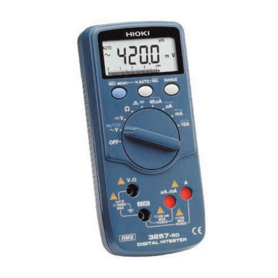
Page 11: 第 1 章 各部の名称と機能
―――――――――――――――――――――――――― 第 1 章 各部の名称と機能 LCD ディスプレイ SHIFT/H.AUTO キー RANGE キー REL キー ファンクション スイッチ V,Ω端子 COM 端子 A 端子 μA, mA 端子 ――――――――――――――――――――――― 第 1 章 各部の名称と機能... - Page 12 ―――――――――――――――――――――――――― ファンクション・スイッチ(ファンクション・SW) ファンクションの選択、電源の ON/OFF を行います。 V, Hz/ AC 電圧,周波数,デューティ比 DC 電圧 Ω 抵抗 導通チェック,ダイオードチェック DC/AC50μA 50μA μA DC/AC500μA, 5000μA DC/AC50 mA, 500 mA DC/AC10 A SHIFT/H.AUTO キー V, Hz/ V/ Hz/ DUTY を切り換えます。 を切り換えます。 50μA (DC/AC)を切り換えます。 μA (DC/AC)を切り換えます。 (DC/AC)を切り換えます。 (DC/AC)を切り換えます。 ・オートパワーセーブ機能の解除を行います。...
- Page 13 ―――――――――――――――――――――――――― RANGE キー ・オートレンジ/マニュアルレンジを切り換えます。 ・マニュアルレンジ時のレンジを切り換えます。 ・Hz, DUTY ファンクションでは、 アッテネータレンジを 切 り 換 え ま す。 ア ッ テ ネ ー タ レ ン ジ の 切 換 え は、 RANGE キーを押すごとに上位レンジに移行します。 REL キー リラティブ(相対値表示)機能の起動と解除をします。 (リラティブ機能参照) V,Ω端子 電圧、抵抗ファンクションのときに使用する端子です。 COM 端子 各ファンクションの共通端子です。 (テストリードの黒を 接続します)...
- Page 14 ―――――――――――――――――――――――――― LCD ディスプレイ ・ 小数点 DCV, DC50μA, DCμA, DCmA, DCA 時に点灯 ACV, AC50μA, ACμA, ACmA, ACA 時に点灯 導通チェック時に点灯 ダイオードチェック時に点灯 AUTO オートレンジ動作時に点灯 HOLD HOLD.Auto 機能動作時に点灯 リラティブ機能動作時に点灯 オートパワーセーブ機能動作時に点灯 電池が確度保証電圧 (2.25 V±0.15 V) 以 下になったときに点灯 MkΩ 抵抗測定時、導通チェック時の単位 電圧測定時、ダイオード測定時の単位 μmA 電流測定時の単位 デューティ比のプラススロープ測定時に 点灯 デューティ比のマイナススロープ測定時 に点灯...
-
Page 15: 第 2 章 測定方法
―――――――――――――――――――――――――― 第 2 章 測定方法 感電事故を防ぐため下記のことをお守りくださ い。 ・測定前に必ずファンクションスイッチの位置を 危険 確認してください。 ・ファンクションスイッチを切り換えるときは、 テストリードを被測定物から外してください。 注記 トランスや大電流路など強磁界の発生している近く、 また無線機など強電界の発生している近くでは、正確 な測定ができない場合があります。 ――――――――――――――――――――――― 第 2 章 測定方法... -
Page 16: 電圧測定
―――――――――――――――――――――――――― 2.1 電圧測定 ・最大入力電圧は DC1000 V、 AC1000 Vrms、 また 7 は 10 V・Hz です。最大入力電圧を超えると本 器を破損し人身事故になるので測定しないでく ださい。 危険 ・感電事故を防ぐため、テストリードの先端で電 圧のかかっているラインを短絡しないでくださ い。 ・テストリードによる測定箇所は、安全のため必 ずブレーカの 2 次側で行なってください。 (1) ファンクション・SW を交流の場合には〜V に、 直流の場 V にします。 赤のテストリードを V, Ω端子に、 合には 黒を COM 端子に接続します。 (2) 被測定回路にテストリードを接続し、表示の値を読みます。 (3) マニュアルレンジ操作の場合、RANGE キーを押します。 (AUTO マークが消えます)再びオートレンジにする場合... -
Page 17: 周波数測定
―――――――――――――――――――――――――― 2.2 周波数測定 ・最大入力電圧は DC1000 V、 AC1000 Vrms、 また 7 は 10 V・Hz です。最大入力電圧を超えると本 器を破損し人身事故になるので測定しないでく 危険 ださい。 ・テストリードによる測定箇所は、安全のため必 ずブレーカの 2 次側で行なってください。 (1) ファンクション・SW を〜V にし、 SHIFT/H.AUTO キーを 押します。 (2) 入力のアッテネータを RANGE キーで選択します。 (3) 赤のテストリードを V,Ω端子に、黒を COM 端子に接続 します。 (4) 被測定回路にテストリードを接続し、表示の値を読みます。 注記 ・アッテネータレンジは下記のとおりです。適切なアッテネ... -
Page 18: デューティ比測定
―――――――――――――――――――――――――― 2.3 デューティ比測定 ・最大入力電圧は DC1000 V、 AC1000 Vrms、 また 7 は 10 V・Hz です。最大入力電圧を超えると本 器を破損し人身事故になるので測定しないでく 危険 ださい。 ・テストリードによる測定箇所は、安全のため必 ずブレーカの 2 次側で行なってください。 (1) ファンクション・SW を〜V にし、 SHIFT/H.AUTO キーを 2 回押すと が点灯し、プラススロープ測定状態となり ます。もう 1 回 SHIFT/H.AUTO キーを押すと が点灯 し、マイナススロープ測定状態になります。 (2) 入力のアッテネータを RANGE キーで選択します。 注記... - Page 19 ―――――――――――――――――――――――――― ■ デューティ(DUTY)比測定について デューティ比 (Duty factor, Duty ratio) とはパルス波形にお いて、パルス幅とパルス繰り返し周期との比をいいます。 3257ではこの比を 100 分率で表示しています。 下図の方形波パルスについて、 :パルス幅(プラススロープ) :パルス幅(マイナススロープ) T:パルス繰り返し周期(= tw ) と定義すると、 プラススロープのデューティ比 D は = tw /T×100(%) となります。 同様に、マイナススロープのデューティ比 D は = tw /T×100(%) となります。 方形波パルスとデューティ比 ――――――――――――――――――――――― 第 2 章 測定方法...
-
Page 20: 電流測定
―――――――――――――――――――――――――― 2.4 電流測定 ・電気事故を防止するために、 600 V 以上の電位の 場合、回路内の電流測定は行わないでください。 電流ファンクションの過負荷保護は DC600 V ま たは AC600 Vrms です。 危険 ・電気事故を防止するために、いったん電源を切 ってから接続し、測定してください。 ・電流測定のファンクションに電圧を入力しない でください。電圧を入力すると本器を破損し、 人 身事故になります。 ■ 50μA 測定 (1) ファンクション・SW を 50μA にします。 (2) 赤のテストリードを 50μA 端子に、 黒を COM 端子に接続 します。 (3) SHIFT/H.AUTO キーで DC か AC を選択します。 (4) 被測定回路にテストリードを接続し、表示の値を読みます。... - Page 21 ―――――――――――――――――――――――――― ■ mA 測定(50 mA,500 mA) (1) ファンクション・SW を mA にします。 (2) 赤のテストリードを mA 端子に、 黒を COM 端子に接続し ます。 (3) SHIFT/H.AUTO キーで DC か AC を選択します。 (4) 被測定回路にテストリードを接続し、表示の値を読みます。 (5) マニュアルレンジ操作の場合、RANGE キーを押します。 (AUTO マークが消えます)再びオートレンジにする場合 は、RANGE キーを 1 秒以上押します。 ■ A 測定(10 A) ・10 A レンジの最大許容入力は...
-
Page 22: 抵抗測定
―――――――――――――――――――――――――― 2.5 抵抗測定 ・抵抗ファンクションに電圧を入力しないでくだ さい。電圧を入力すると本器を破損し、 人身事故 危険 になります。 ・電気事故防止のため、電源を切ってから回路内 の測定をしてください。 (1) ファンクション・SW をΩにします。 (2) 赤のテストリードを V,Ω端子に、黒を COM 端子に接続 します。 (3) 被測定回路にテストリードを接続し、表示の値を読みます。 (4) マニュアルレンジ操作の場合、RANGE キーを押します。 (AUTO マークが消えます)再びオートレンジにする場合 は、RANGE キーを 1 秒以上押します。 ――――――――――――――――――――――― 第 2 章 測定方法... -
Page 23: 導通チェック
―――――――――――――――――――――――――― 2.6 導通チェック ・導通チェックファンクションに電圧を入力しな いでください。電圧を入力すると本器を破損し、 危険 人身事故になります。 ・電気事故防止のため、電源を切ってから回路内 の測定をしてください。 (1) ファンクション・SW を にします。 (2) 赤のテストリードを V,Ω端子に、黒を COM 端子に接続 します。 (3) 導通/ダイオードの切換えは、SHIFT/H.AUTO キーで行 います。 (4) 導通チェック時は マークを表示します。 (5) 被測定回路にテストリードを接続します。 (6) 導通時 (しきい値:100 Ω±80 Ω以下) に、 ブザーが鳴り、 抵抗値を表示します。 (500 Ωレンジ固定) ――――――――――――――――――――――― 第 2 章 測定方法... -
Page 24: ダイオードチェック
―――――――――――――――――――――――――― 2.7 ダイオードチェック ・ダイオードチェックファンクションに電圧を入 力しないでください。電圧を入力すると本器を 危険 破損し、人身事故になります。 ・電気事故防止のため、電源を切ってから回路内 の測定をしてください。 (1) ファンクション・SW を にします。 (2) 赤のテストリードを V,Ω端子に、黒を COM 端子に接続 します。 の切換えは、SHIFT/H.AUTO キーで行います。 (4) ダイオードチェック時は マークを表示します。 (5) 被測定回路にテストリードを接続します。 (6) 正常なシリコンダイオードでは、 順方向電圧 0.4 V〜0.7 V を表示します。逆方向では、開放端子電圧(1.7 V 以下) を表示します。 ダイオードが短絡している場合は 0 V 付近 を、断線している場合は順方向で開放端子電圧を示しま す。... -
Page 25: Hold.auto 機能
―――――――――――――――――――――――――― 2.8 HOLD.Auto 機能 HOLD.Auto 機能は、導通およびダイオードチェックを除く 全ての測定ファンクションで、測定値の最大(電圧、電流、 周波数、DUTY 測定時) 、あるいは最小(抵抗測定時)の値を 表示固定する機能です。 SHIFT/H.AUTO キーを 1 秒以上押し続けると、 HOLD マーク が点灯します。 再度 SHIFT/H.AUTO キーを 1 秒以上押しつづけると解除さ れ HOLD マークは消灯します。 注記 HOLD.Auto 機能はファンクションの切換え、 REL キーの 操作、または電源を切ることでも解除できます。 ■ 電圧、電流、周波数,DUTY 測定の場合 ・測定値が不感領域のときは表示を書き換えません。このと き マークは点滅しています。 HOLD ・測定値が不感領域から外れた場合の最大測定データの表示 を固定し、確認音(ブザーがピッと鳴る)で知らせます。 ・再び表示値を超える測定値が得られるまで表示を書き換え ません。このとき... -
Page 26: オーバーフロー警告機能
―――――――――――――――――――――――――― 注記 AC/DC560 mV レンジには、 HOLD.Auto 機能はありませ ん。 ■ 抵抗測定の場合 ・測定値が OF のときは表示を書き換えません。このとき HOLD マークは点滅しています。 ・測定値の最小測定データの表示を固定し、確認音(ブザー がピッと鳴る)で知らせます。 ・再び表示値より小さな測定値が得られるまで表示を書き換 えません。このとき HOLD マークは連続点灯しています。 ・測定値が再び OF になると、測定回路より切り離されたも のと判断し、次に測定データが得られるまで表示は固定し たままで HOLD マークが点滅を始めます。 2.9 オーバーフロー警告機能 電圧および電流測定時、 測定値が最大表示値 (5610 カウント) を超えた場合に極性を含めた OF 表示、およびブザーを鳴ら す機能です。 注記 DCV の最高レンジ、 10 A レンジでは 「1010」 カウントを 超えた場合に、また... -
Page 27: リラティブ(相対値表示)機能
―――――――――――――――――――――――――― 2.10 リラティブ(相対値表示)機能 リラティブ機能は全てのファンクションで動作し、測定デー タからデータ補正値(基準値)をマイナスする演算処理を行 い、演算結果を表示する機能です。 REL キーを押すと、REL マークが点灯します。再度 REL キ ーを押すと解除され REL マークは消灯します。 リラティブ機能に設定された時点で以下の動作を行います。 (1) 測定レンジを固定します。オートレンジ動作の場合はレ ンジホールドされ、マニュアルレンジ動作になります。 (2) 表示されているデータを基準値としてセットします。 (3) 基準値をセットするとき、 表示データがオーバーフローの 場合は、基準値に 0000 をセットします。 (4) 測定データがオーバーフローの場合は極性を含めたオー バーフロー表示を行います。 (5) アナログバーグラフは、測定データを表示します。 (6) オーバーフロー警告機能は、測定データにより動作しま す。 (オーバーフロー警告機能参照) 注記 リラティブ機能は、ファンクションの切換え、 SHIFT/H.AUTO キー、RANGE キーの操作、または電 源を切ることでも解除できます。 ――――――――――――――――――――――― 第... -
Page 28: オートパワーセーブ機能
―――――――――――――――――――――――――― 2.11 オートパワーセーブ機能 オートパワーセーブ機能は、 最終操作をしてから約 30 分後に 自動的にパワーセーブ状態になる機能です。電源を入れると、 自動的にオートパワーセーブ機能が働きます。 (APS マーク 点灯) オートパワーセーブモードから復帰させたい場合は、ファン クション・SW,SHIFT/H.AUTO キー,RANGE キー,REL キーのいずれかを操作してください。 ■ オートパワーセーブ機能の解除 パワーオンオプションにより、オートパワーセーブ機能を解 除することができます。機能を解除する場合は、 SHIFT/H.AUTO キーを押しながら電源を投入し、確認音 (ブザーがピッと鳴る)がでるまで SHIFT/H.AUTO キーを押 し続けます。電源を切るまでは、オートパワーセーブ機能は 解除された状態となります。 (APS マーク消灯) 注記 パワーセーブ状態では、LCD の表示を OFF にしますが、 電源は OFF にされていません。 パワーセーブ状態から復 帰する場合は、すべてリセットされます。長時間連続使 用したい場合はあらかじめオートパワーセーブを解除し てください。 ―――――――――――――――――――――――... -
Page 29: 第 3 章 仕様
―――――――――――――――――――――――――― 第 3 章 仕様 3.1 一般仕様 測定方式 二重積分方式 交流測定方式 真の実効値測定方式 表示方式 TN型液晶表示体 1/4Duty ダイナミック 駆動 最大測定カウント 3 桁「5610」 ただし Hz ファンクションのみ「14999」 極性表示 − マークのみ自動点灯 電池消耗表示 マーク点灯 レンジ切換え オートレンジおよびマニュアルレンジ (電流測定はファンクション内のみ) フ ァ ン ク シ ョ ン ス イ ッ チ ロータリースイッチ サ... - Page 30 ―――――――――――――――――――――――――― 最大定格動作電圧 DCV, ACV, Hz, DUTY: DC1000 V/AC750 Vrms (sin) または V・Hz Ω:DC600 V/AC600 Vrms (sin) DCA, ACA: 56μA〜560 mA レンジ: ヒューズ保護 1 A/600 V 10 A レンジ:ヒューズ保護 10 A/600 V 耐電圧 ケース−入力端子間 AC7.4 kVrms sin (50/60 Hz 1 分間) ノイズ除去...
-
Page 31: 確度表
―――――――――――――――――――――――――― 3.2 確度表 23℃±5℃,80% rh 以下 ただし結露しないこと ■ 電圧測定 過負荷保護 ファンクション レンジ 測定確度 入力インピーダンス (1分間) 560.0 mV ±0.35%rdg.±4dgt. DC1000 V/ 約11 MΩ 5.600 V ±0.35%rdg.±2dgt. AC750 56.00 V Vrms(sin) ±0.6% rdg.±2dgt. 560.0 V 約10 MΩ または 1000 V ±1.0%rdg.±2dgt. V・Hz 560.0 mV ±2.0%rdg.±8dgt. - Page 32 ―――――――――――――――――――――――――― ■ DUTY 比測定 ファンクション レンジ 測定確度 周波数範囲 100.0 % ±1.0%rdg.±15dgt. 10 Hz〜1 kHz (5〜95%) ±1.0%rdg.±50dgt. 1〜10 kHz ・測定確度は、デューティ比10%〜90%の矩形波(5 Vp‑p)について規定 ・5.0%以下および95.0%以上は、 −−−− 表示 ・過負荷保護(1分間):DC1000 V/AC750 Vrms(sin)または10 V・Hz ■ 抵抗/導通/ダイオード測定 過負荷保護 ファンクション レンジ 測定確度 開放端子電圧 (1分間) Ω 560.0 Ω ±1.0%rdg.±6dgt. DC600 V/ 約0.3 V 5.600kΩ...
- Page 33 ―――――――――――――――――――――――――― ■ 電流測定 過負荷保護 ファンクション レンジ 測定確度 内部抵抗 (1分間) 56.00μA ±1.5%rdg.±4dgt. 10.5 kΩ以下 56 μA〜 560.0μA ±1.5%rdg.±4dgt. 110 Ω以下 560 mAレンジ 5600μA ±1.5%rdg.±4dgt. 110 Ω以下 1 A/600 V 56.00 mA ±1.5%rdg.±4dgt. 3 Ω以下 ヒューズ 560.0 mA ±1.5%rdg.±4dgt. 3 Ω以下 10.00 A ±1.5%rdg.±4dgt.
- Page 34 ―――――――――――――――――――――――――― ――――――――――――――――――――――― 第 3 章 仕様...
-
Page 35: 第 4 章 保守・サービス
―――――――――――――――――――――――――― 第 4 章 保守・サービス 4.1 電池およびヒューズの交換方法 ・感電事故を避けるため、テストリードを被測定 物より外してからケースを開け、 電池、 ヒューズ を交換してください。また、交換後は必ず ケー スをしてから、ねじ止め後使用してください。 ・電池交換するときは極性+−に注意し、逆挿入 しないでください。性能劣化や液漏れの原因と なります。また、 必ず指定の電池と交換してくだ さい。 警告 ・使用済の電池をショート、 分解、 火の中に投入し ないでください。破裂する恐れがあり、危険で す。 ・使用済の電池は、地域で定められた規則に従っ て処分してください。 ・ヒューズ交換は、 指定された形状と定格電流、 電 圧のものを使用してください。指定以外のヒュ ーズを用いたりヒューズホルダを短絡すると、 人身事故になるので注意してください。 ――――――――――――――――――――――― 第 4 章 保守・サービス... - Page 36 ―――――――――――――――――――――――――― μA, mA および A 端子には、 回路保護の目的でヒューズが入 っています。電流測定ができないときは、過電流によるヒュ ーズの断線が考えられます。 図を参照し、以下の手順で交換してください。 (1) テストリードを測定回路から外し、 ファンクション・SW が OFF になっていることを確認します。 (2) 下ケース(本体底面)を上にし、プラスドライバーを使用 してケース止めネジを 3 本外します。 (3) 下ケースを持ち上げて外します。 (4) 単 4 形マンガン乾電池(R03)×2 個、 または断線ヒューズを 交換します。ヒューズは、 μA、 mA 用端子と 10 A 用端子 が有りますので、間違えないようにしてください。 (5) 下ケースを取り付け、ねじ止めします。 単 4 形マンガン乾電池 10 A 端子用ヒューズ...
-
Page 37: 本器のクリーニング
―――――――――――――――――――――――――― 4.2 本器のクリーニング 本器の外装の汚れをとるときは、柔らかい布に水または中性 洗剤を少量含ませ軽く拭いてください。ベンジン、アルコー ル、アセトン、エーテル、シンナー、ガソリン、ラッカー、 ケトン系を含む洗剤は絶対に使用しないでください。変形、 変色することがあります。 4.3 サービス 故障と思われるときは、電池の消耗、ヒューズ、テストリー ドの断線を確認してから、お買上店か最寄りの営業所に送っ てください。輸送中に破損しないように梱包し、故障内容も 書き添えてください。輸送中の破損については保証しかねま す。 ――――――――――――――――――――――― 第 4 章 保守・サービス... -
Page 38: 保証について
―――――――――――――――――――――――――― 4.4 保証について この製品は、弊社の厳密なる検査を経てお届けしたもの です。万一ご使用中に故障が発生した場合は、お買い求 め先に依頼してください。 1. 本器の保証期間は購入日より 3 年間です (ご購入日が不明 の場合は、製品製造月から 4 年を目安とします) 。 2. 取扱説明書・本体注意ラベルなどの注意事項にしたが った正常な使用・保管状態で保証期間内に発生した故 障は、弊社規定により無償修理いたします。ただし、 確度は除きます。 3. 保証期間内でも、次の場合には有償修理となります。 ・本体から取り外し可能なテストリード・プローブ・キ ャリングケース・コード類 ・お客様で修理や改造をされた場合 ・お買い上げ後の輸送や落下等による故障 ・本体のきずや汚れなど外観上の変化 ・火災、地震等天災地変および不可抗力での人災、事故に よる故障 ・電池など消耗部品および取扱説明書の交換 ・その他弊社の責任とみなされない故障 ――――――――――――――――――――――― 第 4 章 保守・サービス... - Page 39 HIOKI 3257 ディジタルハイテスタ 取扱説明書 発 行 年 月 2000 年 10 月 改訂 5 版 編 集・ 発 行 日置電機株式会社 販売支援課 〒386-1192 長野県上田市小泉 81 TEL: 0268-28-0560 FAX: 0268-28-0579 E-mail: info@hioki.co.jp Printed in Japan 3257A980-05 ・本書の内容に関しては万全を期していますが、ご不明な 点や誤りなどお気づきのことがありましたら、 本社 販売 支援課または最寄りの営業所までご連絡ください。 ・本書は改善のため予告なしに記載事項を変更すること があります。...
- Page 41 3257 DIGITAL HiTESTER INSTRUCTION MANUAL...
- Page 43 Contents Introduction Inspection Safety Notes Notes on Use Chapter 1 Names and Functions of parts Chapter 2 Measurement Procedures 2.1 Voltage Measurement 2.2 Frequency Measurement 2.3 Duty Factor Measurement 2.4 Current Measurement 2.5 Resistance Measurement 2.6 Continuity Checking 2.7 Diode Check 2.8 HOLD.Auto Function 2.9 Overvoltage warning function 2.10 Relative (Relative display) function 2.11 Auto Power Save Function...
- Page 44 Chapter 4 Maintenance and Service 4.1 Changing the Batteries and Fuses 4.2 Service 4.3 Cleaning...
-
Page 45: Introduction
――――――――――――――――――――――――――― Introduction Thank you for purchasing this HIOKI "3257 DIGITAL HiTESTER." To get the maximum performance from the unit, please read this manual first, and keep this at hand. Inspection When the unit is delivered, check and make sure that it has not been damaged in transit. -
Page 46: Safety Notes
――――――――――――――――――――――――――― Safety Notes WARNING This equipment is designed to according to IEC 61010-1 Safety Standards, and has been tested for safety prior to shipment. During high voltage measurement, incorrect measurement procedures could result in injury or death, as well as damage to the equipment. Please read this manual carefully and be sure that you understand its contents before using the equipment. - Page 47 ――――――――――――――――――――――――――― This Instruction Manual provides information and warnings essential for operating this equipment in a safe manner and for maintaining it in safe operating condition. Before using this equipment, be sure to carefully read the following safety notes. Safety symbols ・...
- Page 48 ――――――――――――――――――――――――――― The following symbols are used in this Instruction Manual to indicate the relative importance of cautions and warnings. Indicates that incorrect operation presents extreme danger of accident DANGER resulting in death or serious injury to the user. Indicates that incorrect operation presents significant danger of accident WARNING resulting in death or serious injury to...
-
Page 49: Notes On Use
――――――――――――――――――――――――――― Notes on Use In order to ensure safe operation and to obtain maximum performance from the unit, observe the cautions listed below. DANGER Before taking a measurement, check the position of the function switch. Do not measure voltage outside the set voltage range. Doing so may damage the unit or cause an accident that might result in injury or death. - Page 50 ――――――――――――――――――――――――――― WARNING To prevent electric shock, do not allow the unit to become wet and do not use the unit when your hands are wet. Do not attempt to adjust or repair the unit with the case open and with voltage being generated and input.
- Page 51 ――――――――――――――――――――――――――― CAUTION ・ Do not store or use the unit where it will be exposed to direct sunlight, high temperatures, high humidity, or condensation. If exposed to such conditions, the unit may be damaged, the insulation may deteriorate, and the unit may no longer satisfy its specifications.
- Page 52 viii ――――――――――――――――――――――――――― ―――――――――――――――――――――――― Notes on Use...
-
Page 53: Chapter 1 Names And Functions Of Parts
――――――――――――――――――――――――――― Chapter 1 Names and Functions of parts LCD Display SHIFT/H.AUTO Key RANGE Key REL key Function Switch V, Ω Terminal COM Terminal A Terminal μA, mA Terminal ―――――――――――――――――――――――― Chapter 1 Names and Functions of parts... - Page 54 ――――――――――――――――――――――――――― Function Switch Selects functions, and turns the unit on and off. AC voltage, Frequency and Duty V, Hz/ factor DC voltage Ω Resistance Continuity check/Diode check 50μA 50μA DC /AC μA 500μA, 5000μA DC /AC 50 mA, 500 mA DC /AC 10 A DC /AC SHIFT / H.AUTO Key V, Hz/...
- Page 55 ――――――――――――――――――――――――――― With /〜 A function, switches between DC and AC. ・ Disables the Auto Power Save function. (See "Auto Power Save") ・ Starts and disables the HOLD.Auto function. (See "HOLD.Auto Function") RANGE Key ・ Switches between Auto Range and Manual Range.
- Page 56 NOTE the function switch to avoid misoperation. When operating the function switch leaving the test lead connected to the terminal, there is a risk of damage to the 3257. LCD Display Decimal point ・ Lights during VDC, 50 μADC, μADC, mADC and ADC measurement.
- Page 57 ――――――――――――――――――――――――――― Indicates the units during voltage measurement or diode checking μmA Indicates the units during current measurement Lights during duty factor measurement (plus side slope) Lights during duty factor measurement (minus side slope) Indicates the unit during duty factor measurement Bar Graph Scale display 56 dots bar graph display (with polarity indication) ――――――――――――――――――――――――...
- Page 58 ――――――――――――――――――――――――――― ―――――――――――――――――――――――― Chapter 1 Names and Functions of parts...
-
Page 59: Chapter 2 Measurement Procedures
――――――――――――――――――――――――――― Chapter 2 Measurement Procedures WARNING Even when the shutter is closed, there insulating clearance around the terminals is not safe. Be careful when connecting test leads. The changing of the function switch when replacing the test terminals requires disconnection of the test leads from the item being measured and then the disconnection of the test leads from the terminals. -
Page 60: Voltage Measurement
――――――――――――――――――――――――――― 2.1 Voltage Measurement DANGER The maximum allowable input is 1000 VDC, 750 7 Vrms, or 10 V・Hz. Do not measure voltage in excess of these limitations, as doing so may damage the unit or cause an accident that might result in injury or death. -
Page 61: Frequency Measurement
――――――――――――――――――――――――――― 2.2 Frequency Measurement DANGER The maximum allowable input is 1000 VDC, 750 7 Vrms, or 10 V・Hz. Do not measure voltage in excess of these limitations, as doing so may damage the unit or cause an accident that might result in injury or death. - Page 62 ――――――――――――――――――――――――――― ・ Select suitable attenuators referring to the NOTE following list. But only the Auto Range is available for the frequency range. ・ For frequency measurement, the bar graph gives the attenuator condition. (Scale number in the bar graph is equivalent n...
-
Page 63: Duty Factor Measurement
――――――――――――――――――――――――――― 2.3 Duty Factor Measurement DANGER The maximum allowable input is 1000 VDC, 750 7 Vrms, or 10 V・Hz. Do not measure voltage in excess of these limitations, as doing so may damage the unit or cause an accident that might result in injury or death. - Page 64 ■ About Duty Factor measurement Duty Factor shows the ratio between pulse width and pulse period. 3257 displays this ratio by percentage. In the square wave shown in the figure below, tw and tw are the pulse width (plus and minus side slope, respectively) and T is the pulse period.
-
Page 65: Current Measurement
――――――――――――――――――――――――――― 2.4 Current Measurement DANGER Do not use the tester to measure current when the electric potential is 600 V or greater. The current function overload protection trips at either 600 VDC, 600 Vrms. To prevent electrical accidents, turn the power off before connecting the test leads and then take measurements. - Page 66 ――――――――――――――――――――――――――― ■ Microamp Measurement (500 μA, 5000 μA,) 1. Set the function switch to μA. 2. Connect the red test lead to the μA terminal, and the black to the COM terminal. 3. Use the SHIFT/H.AUTO key to select DC or 4.
- Page 67 ――――――――――――――――――――――――――― ■ Amp Measurement (10 A) WARNING In the 10 A range, the maximum allowable input is 10 A in both rms and DC. In the 10 A range, the measuring time is continuous up to 7 A, and one minute or less from 7 A to 10 A.
-
Page 68: Resistance Measurement
――――――――――――――――――――――――――― 2.5 Resistance Measurement DANGER Do not input voltage to the resistance measurement function. Doing so may damage the unit or cause an accident resulting in injury or death. 1. Set the function switch to Ω. 2. Connect the red test lead to the V, Ω terminal, and the black to the COM terminal. -
Page 69: Continuity Checking
――――――――――――――――――――――――――― 2.6 Continuity Checking DANGER Do not input voltage to the continuity checking function. Doing so may damage the unit or cause an accident resulting in injury or death. 1. Set the function switch to 2. Connect the red test lead to the V, Ω terminal, and the black to the COM terminal. -
Page 70: Diode Check
――――――――――――――――――――――――――― 2.7 Diode Check DANGER Do not input voltage to the diode checking function. Doing so may damage the unit or cause an accident resulting in injury or death. To avoid electrical accidents, turn off the power before measuring a circuit. 1. -
Page 71: Hold.auto Function
――――――――――――――――――――――――――― 2.8 HOLD.Auto Function HOLD.Auto Function can display the maximum value during voltage, current or frequency, duty factor measurement or minimum value during resistance measurement. When pressing the SHIFT/H.AUTO key for at least 1 second, the indicator lights. To HOLD cancel it press the key again for at least 1 second. - Page 72 ――――――――――――――――――――――――――― ・ When the measured value is less than the dead zone again, interprets it to be cut off from the circuit to be measured, leaving it fixed until getting a new value higher than the dead zone until the interval, the HOLD indicator starts to go on and off.
-
Page 73: Overvoltage Warning Function
――――――――――――――――――――――――――― 2.9 Overvoltage warning function During voltage or current measurement, the "OF" indication appears indicating polarity and overvoltage and the buzzer sounds when the reading exceeds the maximum value (5610 dgt.). A warning is given if reading exceeds "1010" NOTE in the maximum range of the DC V setting or 10 A range, or "760"... -
Page 74: Relative (Relative Display) Function
――――――――――――――――――――――――――― 2.10 Relative (Relative display) function Relative function operates on all measurement functions. This function displays the result of subtracting the reference data from the measurement data. When pressing the REL Key, the REL indicator lights. To cancel it press the key again, then the indicator will go out. - Page 75 ――――――――――――――――――――――――――― Relative function is disabled by changing NOTE functions, by pressing SHIFT/H.AUTO Key or RANGE key, or by turning off the power switch. ―――――――――――――――――――――――― Chapter 2 Measurement Procedures...
-
Page 76: Auto Power Save Function
――――――――――――――――――――――――――― 2.11 Auto Power Save Function ・ The Auto Power Save function automatically activates the Power Save mode about 30 minutes after the last operation. ・ The Auto Power Save function is automatically enabled as soon as the power is turned on (the APS indicator lights). -
Page 77: Chapter 3 Specifications
――――――――――――――――――――――――――― Chapter 3 Specifications 3.1 General Specifications Dual integration Measurement System AC Measurement True RMS measurement System Type of Display TN type LCD, 1/4 Duty, Dynamic Drive. 3-1/2 dgt., 5610 max. (however Maximum measurement count with the Hz function, up to 14999) Automatically lights only when ’−’. - Page 78 ――――――――――――――――――――――――――― 9170 TEST LEADS Accessories 9378 CARRYING CASE Instruction manual Two R03 manganese batteries Rated supply voltage 1.5 VDC×2, Power Supply two R03 manganese batteries Maximum rated VDC, VAC, Hz, Duty factor : 1000 7 VDC/750 Vrms (sin) or 10 V・Hz voltage Ω: 600 VDC/600 Vrms (sin)
- Page 79 ――――――――――――――――――――――――――― 0 ℃ to 50℃, 80% rh or less Operating Temperature and 32 F to 122 F, 80% rh or less (no condensation) Humidity Range Storage Temperature -20℃ to 60℃, 70% rh or less -4 F to 140 F, 70% rh or less and Humidity Range (no condensation) Temperature...
-
Page 80: Accuracy Chart
――――――――――――――――――――――――――― 3.2 Accuracy Chart 23℃±5℃(73 F±5 F), 80% rh or less (no condensation) ■ Voltage measurement Function Range Accuracy Input Over impedance Protection for 1 minute 560.0 mV ±0.35%rdg.±4dgt. Approx.11 MΩ 1000 VDC/ 5.600 V ±0.35%rdg.±2dgt. 750 VAC sin 56.00 V ±0.6%rdg.±2dgt. - Page 81 ――――――――――――――――――――――――――― ■ Duty factor measurement Function Range Accuracy 100.0 % ±1.0%rdg.±15dgt. 10 Hz to 1 kHz (5 to 95%) ±1.0%rdg.±50dgt. 1 to 10 kHz ・The accuracy figures are determined with the square wave (5 V p‑ p) from 10% to 90% of duty factor. ‑‑‑‑...
- Page 82 ――――――――――――――――――――――――――― ■ Current measurement Function Range Accuracy Input Over Protection impedance for 1 minute (less than) 56.00μA ±1.5%rdg.±4dgt. 10.5 kΩ 1 A/600 V 560.0μA ±1.5%rdg.±4dgt. 110 Ω FUSED 5600μA ±1.5%rdg.±4dgt. 110 Ω (56μA to 56.00 mA ±1.5%rdg.±4dgt. 3 Ω 560 mA range) 560.0 mA ±1.5%rdg.±4dgt.
- Page 83 ――――――――――――――――――――――――――― Chapter 4 Maintenance and Service 4.1 Changing the Batteries and Fuses WARNING To avoid electric shock when replacing the batteries and fuses, first disconnect the test leads from the object to be measured. Also, after replacing the batteries and fuses, always replace the cover and tighten the screws before using the tester.
- Page 84 ――――――――――――――――――――――――――― In order to protect the circuitry, a fuse is provided for μA, mA or A terminals. When current does not measured normally, the fuse might be blown by over current. Referring to the diagram, change the batteries or fuses as follows: 1.
- Page 85 If the unit is not functioning properly, check the batteries, the test leads wiring and fuse blowing. If a problem is found, contact your dealer or HIOKI representative. Pack the unit carefully so that it will not be damaged during transport, and write a detailed description of the problem.
- Page 86 ――――――――――――――――――――――――――― ―――――――――――――――――――――――― Chapter 4 Maintenance and Service...
- Page 89 HIOKI 3257 DIGITAL HiTESTER Instruction Manual Publication date: October 2000 Revised edition 5 Edited and published by HIOKI E.E. CORPORATION Technical Sales Support Section All inquiries to Sales and Marketing International Department 81 Koizumi, Ueda, Nagano, 386-11, Japan FAX: 0268-28-0568 TEL: 0268-28-0562 E-mail: os-com@hioki.co.jp...
- Page 90 HEAD OFFICE 81 Koizumi, Ueda, Nagano 386-1192, Japan TEL +81-268-28-0562 / FAX +81-268-28-0568 E-mail: os-com@hioki.co.jp HIOKI USA CORPORATION 6 Corporate Drive, Cranbury, NJ 08512, USA TEL +1-609-409-9109 / FAX +1-609-409-9108 3257A980-05 00-10-0004H Printed on recycled paper...
Need help?
Do you have a question about the 3257 and is the answer not in the manual?
Questions and answers