Table of Contents
Advertisement
Quick Links
USER GUIDE FOR FUEL LEVEL
SENSOR RESISTIVE OUTPUT
CAP10G
CAP10G-MN-EN-01
This document is applied for the following products
1. Introduction
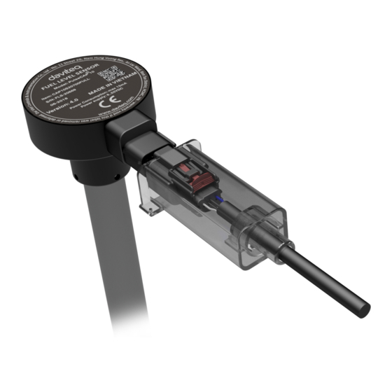
CAP10G is the industrial version of PulseCAP10, designed specifically for generator fuel monitoring applications. The
CAP10 has 240..33 ohms resistor output allowing direct connection to a generator controller. It is compatible with most
popular generator controllers on the market such as DEEPSEA, EMKO, DATAKOM, COM AP, MGS, SMART GEN,
WOODWARD, POWERCOMMAND ... CAP10G with high precision up to 0.5%. Measuring range from 100mm - 3500mm.
The sensor has CE EMC certification according to EN61236-1 standard.
2. Notes
The technicians who install sensor, must be graduated from college of mechanic or electric.
The mechanical installation staff (drill, cut, grind, etc.) must have skills in mechanical engineering.
The electrical installation staff (connect, etc.) must have skills in electrical engineering.
The technician must be trained before using.
3. Safety
CAP10G is intended to use with Diesel Oil, Vegetable Oil.
CAP10G must not be used with other flammable fluid such as Gasoline, Alcohol, Ethanol, Acetone, Toluene or
other solvents.
OCT-2020
Advertisement
Table of Contents

Related Manuals for daviteq CAP10G


Summary of Contents for daviteq CAP10G
- Page 1 The electrical installation staff (connect, etc.) must have skills in electrical engineering. The technician must be trained before using. 3. Safety CAP10G is intended to use with Diesel Oil, Vegetable Oil. CAP10G must not be used with other flammable fluid such as Gasoline, Alcohol, Ethanol, Acetone, Toluene or other solvents.
-
Page 2: Note Before Installation
Be careful while drilling, cutting, grinding, etc. The fuel tank or other flammable fluid. Daviteq is not responsible for compensation in case of explosion to bodily injury or property damage. 4. Note Before Installation Read specifications thoroughly and make sure that its output are suitable to reading devices. - Page 3 7. Tools Tool Name Tool Name Drilling machine Drill (Φ38) Pump Silicone gasket Rivet clippers Twist drill 4 mm (In case of using stainless steel (In case of using stainless steel rivet) rivet) Tube cutter Electrical tape Swivel Blade Cutting pliers Hacksaw Phillips screwdriver File...
- Page 4 8. Sensor Installation Guidance Step Discription Note Some tank have been welded with oil filter and have float level sensor installed, so it is Remove fuel: Remove all fuel from the tank. necessary to take out the float level sensor before removing the fuel.
- Page 5 Sensor cutting: After flange installation, we determine the length of the sensor to be installed as picture below: C = L+20+20-(H+14) => C = L+26-H (mm) C: Length to be cut. L: Original length of the sensor. H: Height of the tank. *Example: Sensor length is L = 2000, H = 1700 mm =>...
- Page 6 Final: Place the O-ring on the top of the threads, ensure that it can touch the aluminum housing of the sensor (as below picture): Install sensor into the threads of flange and turn it in clockwise direction. Using the O-ring enables to rotate the sensor within 180 degrees from final tighten position and assuring that the oil will be not spilled (as below picture): Use the 2mm Allen key to lock the hex bolt to protect the sensor rotate backwards.
- Page 7 10.1 Follow Labels in Wires: Each cable includes wires which are marked labels according to types of connection. (user should not cut these labels before installation to avoid confusing) 10.2 Follow Wire Colors: White: PWR+(8...50VDC) Blue: PWR-(OVDC) Black: Resistive Output (240.33 Ohm) Recommend to use 24VDC power.
-
Page 8: Troubleshooting
11. Periodic Cleaning Guidance 1. Periodically clean the oil tank 2, 3 or 6 months depending on usage and contamination. 2. Periodically clean the sensor and filter footer 2, 3 or 6 months by: Cover a sensor's vent before using the air sprayer for another. Remove and clean the filter footer. -
Page 9: Warranty
13. Warranty Warranty is applied for CAP10G fuel level sensor manufactured by Daviteq Technologies Inc (Daviteq). CAP10G fuel level sensor will be warranted for a period of eighteen (18) months from date of delivery. 13.1 Free Warranty Condition: 1. Manufacturer undertakes to guarantee within 18 months. - Page 10 Daviteq Technologies Inc No.11 Street 2G, Nam Hung Vuong Res., An Lac Ward, Binh Tan Dist., Ho Chi Minh City, Vietnam. Tel: +84-28-6268.2523/4 (ext.122) Email: info@daviteq.com | www.daviteq.com Revision #2 Created Fri, Oct 16, 2020 6:19 AM by Kiệt Anh Nguyễn Updated Fri, Oct 16, 2020 7:31 AM by Kiệt Anh Nguyễn...
Need help?
Do you have a question about the CAP10G and is the answer not in the manual?
Questions and answers