Table of Contents
Advertisement
Quick Links
Manual for Sigfox-Ready
Ultrasonic Level Sensor for Trash
bin - WSSFC-ULA | FW2
Thank you very much for choosing Daviteq Wireless Sensors. We are the leading wireless sensor manufacturer in the
World. We have a wide range of wireless sensors which support different connectivity like LoRaWAN, Sigfox, Sub-GHz,
NB-IoT...Please find out more information at
This manual is applied to the following products
Item code
WSSFC-ULA-01
Information Changes in this version v.s previous version
Item
1
Initial version
To use this product, please refer step by step to the below instructions.
Operating Principle
1. Quick Guide
Reading time: 10 minutes
Finish this part so you can understand and put the sensor in operation with the default configuration from the
factory.
1.1 What is the Sigfox-Ready Ultrasonic Level Sensor for Trash
bin and its principle of operation?
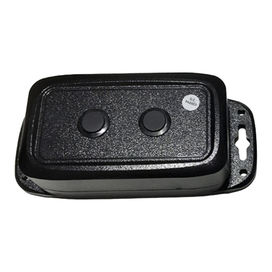
WSSFC-ULA is a Sigfox-Ready sensor with an integrated ultrasonic level sensor that can measure the waste level in the
trash bin. It can be installed in the trash bin with heights from 45 cm to 450 cm.
this
HW Version
2
Changes
Changed by
D.Q.Tuan
Battery
Installation
Configuration
Specification
link.
Firmware Version
Changed Date
01-08-2022
2
Approved by
N.V.Loc
Uplink Payload
Connect to Sigfox Network
Troubleshooting
Calibration
Warranty and Support
Remarks
Approved Date
24-08-2022
Advertisement
Table of Contents

Related Manuals for daviteq WSSFC-ULA-01


Summary of Contents for daviteq WSSFC-ULA-01
- Page 1 - WSSFC-ULA | FW2 Thank you very much for choosing Daviteq Wireless Sensors. We are the leading wireless sensor manufacturer in the World. We have a wide range of wireless sensors which support different connectivity like LoRaWAN, Sigfox, Sub-GHz, NB-IoT...Please find out more information at...
-
Page 2: What's In The Package
It is battery-operated and able to connect to any Sigfox network in the World. It supports all frequency zones such as RC1, RC2, RC3c, RC4, RC5, RC6, and RC7. For the principle operation of the ULA Ultrasonic level sensor, please refer to this link. -
Page 3: Quick Test
1.3 Quick Test With the default configuration, the device can quickly connect to the Sigfox Network by the following steps. Step 1: Prepare the values of communication settings: Device ID Get Devive ID on the device nameplate Device PAC Get Devive PAC on the device nameplate Note: All Sigfox sensors are pre-configured with the correct RC before delivery. -
Page 4: Battery Insertion
DIMENSIONS OF PRODUCT 1.5.1 Battery insertion Please refer to this link for instructions. 1.5.2 Mounting sensor in trash bin Locate the place to mount the sensor: The sensor must be mounted on the top of the trash bin; The sensor surface must be facing down to the bottom of the trash bin; Notes: * The sensor must not be installed in a complete metallic trash bin as the RF signal cannot pass thru the metallic wall;... -
Page 5: Sensor Calibration
MOUNTING SENSOR ON THE MOVABLE LID OF TRASH BIN MOUNTING SENSOR ON THE FIXED TOP WALL OF TRASH BIN MOUNTING SENSOR ON THE MOVABLE LID OF TRASH BIN MOUNTING SENSOR ON THE OPEN-STYLE TRASH BIN To get a strong RF signal, please refer to this link. -
Page 6: Advanced Guide
3.1 Operating principle of the Sigfox-Ready Ultrasonic level sensor 3.1.1 Operating principle of the complete device The Daviteq Sigfox-Ready Ultrasonic level sensor comprises 02 parts connected together: - The Daviteq Sigfox-Ready wireless transmitter; - The Daviteq Ultrasonic level transducer; The Ultrasonic level transducer measures the average distance from the sensor surface to the waste surface in the trash bin. - Page 7 To read the parameters, use the off-line cable as above instruction. Via uplink message, users can read only one parameter, which is the CURRENT_CONFIGURATION. Below tables are the lists of the parameters of the device. Read-only Parameter Table Modbus Modbus Function No.
- Page 8 HIGH_CUT 1E+09 float Read/Write High cut value for calculated value LOW_CUT float Read/Write Low cut value for calculated value SENSOR_BOOT_TIME uint32 Read/Write Boot time sensor/input, in ms NUM_OF_SAMPLE uint16 Read/Write A number of samples filtering function. The higher value, the more filtering 3.3 Calibration for Sigfox-Ready Ultrasonic Level Sensor...
Need help?
Do you have a question about the WSSFC-ULA-01 and is the answer not in the manual?
Questions and answers