Table of Contents
Advertisement
Quick Links
USER GUIDE FOR WIRELESS
SENSOR AC CURRENT INPUT
WS433-AC
WS433-AC-MN-EN-01
This document is applied for the following products
SKU
WS433-AC
WS433-AC-11
Item Code
1. Functions Change Log
HW Ver.
2.5
2. Introduction
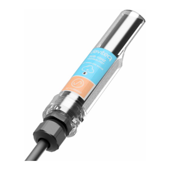
Wireless sensor with 1-channel AC current input 5A to measure the AC current load of your motors, machines...to count
the energy consumption, OVER-load or NO-load detection, run hour counting...It is configured the operation
parameters like data sending interval, health check cycle...remotely from Globiots platform or via ModbusRTU
software. The wireless module can last up to 10 years with a single AA battery.
HW Ver.
2.5
Wireless sensor 1-channel AC current input max 5A, IP67, battery AA 1.5VDC, cable 0.5m length
with PG9 cable gland and wire crimpping connectors for SAFETY
FW Ver.
5.0
FW Ver.
Release Date
DEC-2019
APR-2020
5.0
Functions Change
Change RF data rate by
button
Advertisement
Table of Contents

Summary of Contents for daviteq WS433-AC
- Page 1 USER GUIDE FOR WIRELESS SENSOR AC CURRENT INPUT WS433-AC WS433-AC-MN-EN-01 APR-2020 This document is applied for the following products WS433-AC HW Ver. FW Ver. Wireless sensor 1-channel AC current input max 5A, IP67, battery AA 1.5VDC, cable 0.5m length WS433-AC-11...
-
Page 2: Specification
3. Specification Measuring range 0..5A AC Accuracy 1.0% Resolution 10 bit Temperature Drift < 100 ppm cable 0.5m length with PG9 cable gland and wire crimpping connectors Electrical connection for SAFETY 304SS Adapter PG9/male 1/2""NPT or PG13.5 or M20 to allow direct Optional accessories mounting on Process instruments or electrical panel Data speed... -
Page 4: Operation Principle
(add up to 40 nodes) . After 5 minutes Enb_auto_add_sensors will automatically = 0. Memmap resgisters You can download Modbus Memmap of WS433-CL-FW_V1.9 with the following link: http://filerun.daviteq.com/wl/?id=fnepmO8uKmnp7P5R90Iu4osu8DcZlzjp 5.1.2 Add sensor node into WS433-CL-04 (1) through intermediate WS433-CL-04 (2) and Modbus In case the sensor need to be added to WS433-CL-04 (1) has been installed in a high position, the sensor cannot be brought close to WS433-CL-04 (1). - Page 5 5.3 Configuration 5.3.1 Sensor configuration The WS433-AC wireless sensor measures AC current via CT (Current Transformer). We need to check what the ratio on the CT is printed on the sticker. For example: 50/5A = 10, 75/5A=15, 100/5A = 20, ...
- Page 6 Next, we need to import the configuration file for WS433-CL-04 by importing the csv file: Go to MENU: FILE / Import New / => select the file with name Template for WS433-AC.csv (after unzip the file).
- Page 7 In the row Write_CT_Node , we write the the ratio of the CT of sensor node to co-ordinator id WS433-CL-04 by write the the ratio of the CT in column Setting Value then check the box Func to write the value => the value in the Read Value column show OK, that means the configuration is complete.
- Page 8 You can now connect the Co-ordinator WS433-CL-04 using an RS485 connection to read data from the wireless sensor. 5.3.2 IO Wiring On WS433-AC there are 2 wires marked S1 and S2, we connect the sensor to the current transformer according to S1 with S1 (K) and S2 with S2 (L) as shown below.
-
Page 9: Installation
6. Installation 6.1 Installation location Wireless sensor utilize the ultra-low power 433Mhz RF signal to transmit/receive data with Wireless co-ordinator. To maximize the distance of transmission, the ideal condition is Line-of-sight (LOS) between the two modules. In real life, there is no LOS condition. However, the two modules still communicate each other, but the distance will be reduced significantly. - Page 10 Carefully pull out the top plastic housing in the vertical direction NOTE: Because of O-ring, it requires to have much pulling force at the beginning, therefore please do it carefully to...
- Page 11 avoid the damage of circuit board which is very thin (1.00mm); Insert the AA battery, please take note the poles of battery Insert the top plastic housing and locking by M2 screw...
-
Page 12: Troubleshooting
7. Troubleshooting Phenomena Reason Solutions Check that the battery is empty or not installed No power supply. correctly. The status LED of wireless sensor Configuration function of Reconfigure the led light doesn't light up the LED is not correct. function exactly as instructed. - Page 13 Dai Viet Controls & Instrumentation Company Ltd. No.11 Street 2G, Nam Hung Vuong Res., An Lac Ward, Binh Tan Dist., Ho Chi Minh City, Vietnam. Tel: +84-28-6268.2523/4 (ext.122) Email: info@daviteq.com | www.daviteq.com Revision #4 Created Tue, Apr 7, 2020 2:13 AM by Kiệt Anh Nguyễn...


Need help?
Do you have a question about the WS433-AC and is the answer not in the manual?
Questions and answers