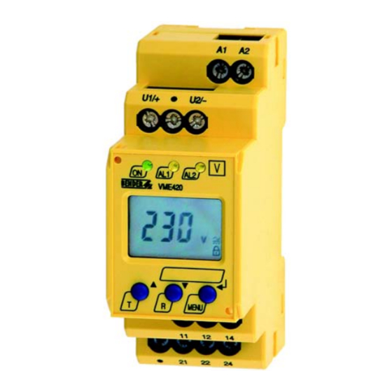
Bender VME420 Manual
Voltage and frequency monitor
Hide thumbs
Also See for VME420:
- Manual (44 pages) ,
- Quick start manual (9 pages) ,
- Quick start manual (9 pages)

Related Manuals for Bender VME420


Summary of Contents for Bender VME420
- Page 1 VME420 Voltage and frequency monitor for monitoring AC/DC systems of 0…300 V, 15…460 Hz for undervoltage, overvoltage, underfrequency, overfrequency VME420_D00026_03_M_XXEN/04.2019 Manual EN...
- Page 2 Bender GmbH & Co. KG P.O. Box 1161 • 35301 Gruenberg • Germany Londorfer Strasse 65 • 35305 Gruenberg • Germany Tel.: +49 6401 807-0 • Fax: +49 6401 807-259 E-Mail: info@bender.de • www.bender.de © Bender GmbH & Co. KG All rights reserved.
-
Page 3: Table Of Contents
Table of Contents 1. Important information ..................5 How to use this manual ................. 5 Technical support: service and support ........... 6 1.2.1 First level support ..................... 6 1.2.2 Repair service ..................... 6 1.2.3 Field service ......................7 Training courses ....................8 Delivery conditions .................. - Page 4 5.5.9 Device information interrogation ............41 5.5.10 History memory interrogation ..............41 Preset function/ factory setting ............... 41 Commissioning ....................42 6. Technical data VME420… ................43 Data in tabular form ..................43 Standards, approvals and certifications ..........47 Ordering information ................... 47 User settings (overview) ................
-
Page 5: Important Information
This manual has been compiled with great care. It might nevertheless contain errors and mistakes. Bender cannot accept any liability for injury to persons or damage to property resulting from errors or mistakes in this manual. -
Page 6: Technical Support: Service And Support
Important information 1.2 Technical support: service and support For commissioning and troubleshooting Bender offers you: 1.2.1 First level support Technical support by phone or e-mail for all Bender products Questions concerning specific customer applications Commissioning Troubleshooting ... -
Page 7: Field Service
Important information 1.2.3 Field service On-site service for all Bender products Commissioning, configuring, maintenance, troubleshooting of Bender products Analysis of the electrical installation in the building (power quality test, EMC test, thermography) Training courses for customers ... -
Page 8: Training Courses
ZVEI (Zentralverband Elektrotechnik- und Elektronikindustrie e. V.) (German Electrical and Electron- ic Manufacturer's Association) also applies. Sale and delivery conditions can be obtained from Bender in printed or elec- tronic format. 1.5 Inspection, transport and storage Inspect the dispatch and equipment packaging for damage, and compare the contents of the package with the delivery documents. -
Page 9: Warranty And Liability
Important information 1.6 Warranty and liability Warranty and liability claims in the event of injury to persons or damage to property are excluded if they can be attributed to one or more of the follow- ing causes: Improper use of the device. ... -
Page 10: Disposal
13 August 2005 must be taken back by the manufacturer and disposed of properly. For more information on the disposal of Bender devices, refer to our homepage at www.bender-de.com -> Service & support. -
Page 11: Safety Instructions
2. Safety instructions 2.1 General safety instructions Part of the device documentation in addition to this manual is the enclosed "Safety instructions for Bender products". 2.2 Work activities on electrical installations Only qualified personnel are permitted to carry out the work necessary to install, commission and run a device or system. -
Page 12: Intended Use
Safety instructions 2.3 Intended use The voltage monitor VME420 monitors AC/DC systems in the frequency range DC/15…460 Hz for undervoltage, overvoltage, underfrequency and overfre- quency. The devices are designed for the nominal voltage range = 0…300 V. Separate supply voltage U is required. -
Page 13: Function
3. Function 3.1 Device features Undervoltage and overvoltage monitoring of AC/DC systems 0…300 V in the frequency range DC/15…460 Hz Preset function: Automatic response value setting for undervoltage and overvoltage, < U and > U as well as for underfrequency and over- frequency <... -
Page 14: Fast Commissioning For Un = 230 V
3. When the conditions 1 and 2 are satisfied, you can connect the voltage monitor to the three-phase system to be monitored according to the wiring diagram (page 22). The following predefined response values will be set automatically: VME420 Preset Response Response... -
Page 15: Function
+ 1 Hz Response value underfrequency ( < f) at 16.7 Hz, 50 Hz, 60 Hz: f - 1 Hz Response value underfrequency ( < f) at 400 Hz: f - 1 Hz Preset VME420 Preset Response value Response value operating range <... -
Page 16: Automatic Self Test
3.7 Functional fault If there is an internal functional fault, all three LEDs flash. The display shows an error code (E01…E32). In such a case please contact the Bender Service. 3.8 Fault memory The fault memory can be activated, deactivated or can be set to continuous mode (con). -
Page 17: Assigning Alarms To The Alarm Relays K/K2
3.11 Password protection (on, OFF) With the password protection activated (on), settings are only possible after entering the correct password (0…999). If you cannot operate your device be- cause you cannot remember your password, please contact info@Bender- service.com. VME420_D00026_03_M_XXDE/04.2019... -
Page 18: Factory Setting Fac
Function 3.12 Factory setting FAC After activating the factory setting, all settings previously changed are reset to delivery status. In addition, the preset function allows automatic adaptation of the response values in relation to the nominal voltage U 3.13 Erasable history memory The first alarm value that occurs will be stored in this memory. - Page 19 Function The fault for K1 shown in the time diagram below, by way of example, has started during the S.AL phase: S.AL The fault for K1 shown in the time diagram below, by way of example, started when the S.AL phase has elapsed: S.AL VME420_D00026_03_M_XXDE/04.2019...
-
Page 20: Frequency Alarm In Case Of Measuring Voltage Failure
Function 3.16 Frequency alarm in case of measuring voltage failure (Menu -> AL -> <U Hz) If the voltage of the monitored system falls to the point where the frequency can no longer be determined, this parameter is used to set how the frequency alarm should behave. -
Page 21: Installation And Connection
4. Installation and connection Only qualified personnel are permitted to carry out the work necessary to install, commission an d run a device or system. Risk of electrocution due to electric shock! Touching live parts of the system carries the risk of: An electric shock ... - Page 22 Installation and connection The front plate cover is easy to open at the lower part identified by an arrow. 1. DIN rail mounting: Snap the rear mounting clip of the device into place in such a way that a safe and tight fit is ensured. Screw fixing: Use a tool to move the rear mounting clips (a second mounting clip is required, see ordering information) to a position that it projects...
-
Page 23: Operation And Setting
5. Operation and setting 5.1 Display elements in use The meaning of the display elements in use is listed in detail in the table be- low. Elemen Display elements Function Undervoltage (Alarm 2), < U, overvoltage (Alarm 1) > U Alarm relay K1, R1, r1, Alarm relay K2... -
Page 24: Function Of The Operating Elements
Operation and setting 5.2 Function of the operating elements Ele- Device front Function ment Power On LED, green AL1, Menu item LEd deactivated: AL1 AL2 LED Alarm 1 lights (yellow): Response value > U reached LED Alarm 2 lights (yellow): Res- ponse value <... -
Page 25: Menu Structure
Operation and setting Ele- Device front Function ment MENU key (> 1.5 s): MENU, Starting the menu mode; Enter key (< 1.5 s): Confirm menu item, submenu item and value. Enter key (> 1.5 s): Back to the next higher menu level. - Page 26 Operation and setting Menu Activa Menu Adjustable parameter Menu item tion Fault memory (on, con, off ) (output Operating mode K1 control) (n.o.) Operating mode K2 (n.c.) LEDs signal relay in alarm state 1 Err Device error at K1 r1 < U Undervoltage K1 (K1: r1 >...
-
Page 27: Display In Standard Mode
Operation and setting Menu Activa Menu Adjustable parameter Menu item tion Parameter setting via password (device Re-establish factory set- control) tings Manual preset Function blocked Display hard / software version History memory for the first alarm value, erasa- 5.4 Display in standard mode By default, the display indicates the voltage across the terminals U1/+ and U2/ -. -
Page 28: Display In Menu Mode
Operation and setting 5.5 Display in menu mode Menu item Adjustable parameter Interrogate and adjust response values: – Undervoltage: < U (AL2) – Overvoltage: > U (AL1) – Hysteresis of the response values: Hys U – Underfrequency: < Hz (AL1 and AL2) –... - Page 29 Operation and setting Menu structure VME420_D00026_03_M_XXDE/04.2019...
-
Page 30: Setting: Response Values For Under-, Overvoltage And Hysteresis
Operation and setting Parameter settings An example is given below on how to change the alarm response value for ov- ervoltage > U. Proceed as follows: 1. Press the MENU/Enter key for more than 1.5 seconds. The flashing short symbol AL appears on the display. 2. - Page 31 Operation and setting Setting the undervoltage response value < U Setting the overvoltage response value> U Setting the hysteresis of the voltage response values VME420_D00026_03_M_XXDE/04.2019...
-
Page 32: Setting: Response Values For Under-, Overfrequency, Hysteresis
Operation and setting 5.5.2 Setting: response values for under-, overfrequency, hysteresis Setting the underfrequency response value < Hz Setting the overfrequency response value > Hz VME420_D00026_03_M_XXDE/04.2019... -
Page 33: Setting: Fault Memory And Operating Principle (Alarm Relays)
Operation and setting Setting the hysteresis of the frequency response values Switch off frequency alarm when the voltage is too low < < < < 5.5.3 Setting: fault memory and operating principle (alarm relays) Deactivating the fault memory VME420_D00026_03_M_XXDE/04.2019... - Page 34 Operation and setting Setting the alarm relay K1 to N/C operation (n.c.) Setting the alarm relay K2 to N/O operation (n.o.) LEDs AL1/AL2 are intended to indicate the alarm state of K1/K2 VME420_D00026_03_M_XXDE/04.2019...
-
Page 35: Assigning Alarm Categories To The Alarm Relays
Operation and setting 5.5.4 Assigning alarm categories to the alarm relays Undervoltage, overvoltage, underfrequency, overfrequency and device-relat- ed error messages of the voltage relay can be assigned to the alarm relays K1 (r1, 1) and K2 (r2, 2. K1 is set at the factory to signal an alarm in the event of overvoltage, and K2 is set to signal an alarm in the event of undervoltage. - Page 36 Operation and setting Alarm relay 1: Deactivating the category overvoltage When an alarm relay (K1/K2) has been deactivated via the menu, an alarm will not be signalled by the respective changeover contact! An alarm will only be indicated by the respective alarm LED (AL1/AL2)! CAUTION This only applies to the out menu setting LEd = off!
-
Page 37: Setting The Time Delays
Operation and setting 5.5.5 Setting the time delays Setting range 0…300 s Response delay for K1 Response delay for K2 Start-up delay during device start Common delay on release for K1 and K2: is only relevant if fault memory M is deactivated) The operating steps for the setting of the response delay t and the start-up... -
Page 38: Factory Setting And Password Protection
Operation and setting 5.5.6 Factory setting and password protection Use this menu to activate the password protection, to change the password or to deactivate the password protection. In addition, you can reset the device to its factory settings. a) Activating the password protection b) Changing the password VME420_D00026_03_M_XXDE/04.2019... - Page 39 Operation and setting c) Deactivating the password protection VME420_D00026_03_M_XXDE/04.2019...
-
Page 40: Restoring Factory Settings
Operation and setting 5.5.7 Restoring factory settings 5.5.8 Manual activation of the preset function VME420_D00026_03_M_XXDE/04.2019... -
Page 41: Device Information Interrogation
Operation and setting 5.5.9 Device information interrogation This function is used to interrogate the hardware (d…) and software (1.xx) ver- sions. After activating this function, data will be displayed as a scrolling text. Once one pass is completed, you can select individual data sections using the Up/Down keys. -
Page 42: Commissioning
0, Off 5.7 Commissioning Prior to commissioning, check proper connection of the voltage monitor. After connecting a brand-new VME420 to a standard system of U = 230 V 50 Hz, the response values are automatically set by the internal preset function:... -
Page 43: Technical Data Vme420
Technical data VME420… 6. Technical data VME420… 6.1 Data in tabular form ( )* = factory setting Insulation coordination acc. to IEC 60664-1/IEC 60664-3 Rated insulation voltage ............................250 V Rated impulse voltage/overvoltage category....................4 kV / III Pollution degree................................3 Protective separation (reinforced insulation) between:... - Page 44 Technical data VME420… Relative uncertainty voltage at 50/60 Hz ..................±1.5 %, ±2 digit Relative uncertainty voltage in the range of 15…460 Hz ..............±3 %, ±2 digit Hysteresis U ............................1…40 % (5 %)* Underfrequency < Hz ........................... 10…500 Hz** Overfrequency >...
- Page 45 Technical data VME420… Switching elements Number of changeover contacts ....................... 2 x 1 (K1, K2) Operating principle ....................... N/C operation / N/O operation ............K2: Err, < U, > U, < Hz, > Hz, S.AL (undervoltage < U: N/C operation n.c.)* ............
- Page 46 Technical data VME420… Connection Connection ........................screw-type terminals Connection properties: rigid/ flexible ..................... 0.2…4 / 0.2…2.5 mm / AWG 24…12 Multi-conductor connection (2 conductors with the same cross section): rigid/ flexible ......................0.2…1.5 mm / 0.2…1.5 mm Stripping length ............................8…9 mm Tightening torque ............................
-
Page 47: Standards, Approvals And Certifications
Technical data VME420… 6.2 Standards, approvals and certifications 6.3 Ordering information Nominal voltage Supply Device Art. No. voltage s type VME420-D-1 AC/DC 0…300 V DC 9.6 V…94 V / B73010001 (push-wire 15…460 Hz AC 15…460 Hz, 16…72 V B7300001W terminals) AC/DC 0…300 V... -
Page 48: User Settings (Overview)
Technical data VME420… 6.4 User settings (overview) Menu Parameter User setting Setting range AL-LED U< PRESET or 6…300 V U> U Hys 1 … 40 % Hz < 1+2 * PRESET or 10…500 Hz Hz > 1+2 * Hz Hys 0.2 Hz... -
Page 49: Index
INDEX Adjustable parameters, list 25 How to use this manual 5 Automatic self test 16 Indication of the alarm state of K1/K2 18 currently measured values Intended use 12 - nominal voltage 27 - rated frequency 27 K1: assignment alarm category 26 K2: assignment alarm category 26 Delay on release toff 17 Deleting the fault alarms 24... - Page 50 Operating elements, function 24 Service 6 Operation and setting 23 Simulated alarm 18 Ordering information 47 Starting a device using a simulated alarm S.AL 18 Starting the menu mode 25 Parameter query and setting Start-up delay t 17 - 28 Support 6 Parameter setting - Activating or deactivating the pass-...
- Page 52 Bender GmbH & Co. KG P.O. Box 1161 • 35301 Gruenberg • Germany Londorfer Strasse 65 • 35305 Gruenberg • Germany Tel.: +49 6401 807-0 • Fax: +49 6401 807-259 E-Mail: info@bender.de • www.bender.de Group Photos: Bender archives...
Need help?
Do you have a question about the VME420 and is the answer not in the manual?
Questions and answers