Bender VMD460-NA Manual
Network and system protection (ns protection) for monitoring the power feed-in of power generation systems
Hide thumbs
Also See for VMD460-NA:
- Manual (85 pages) ,
- Quick start manual (9 pages) ,
- Quick start manual (9 pages)
Table of Contents

Subscribe to Our Youtube Channel
Related Manuals for Bender VMD460-NA


Summary of Contents for Bender VMD460-NA
- Page 1 Manual VMD460-NA Network and system protection (NS protection) for monitoring the power feed-in of power generation systems Software version: D398 V1.1x Display software version: D403 V2.2x VMD460-NA_D00001_01_M_XXEN/08.2013...
- Page 2 Bender GmbH & Co. KG Londorfer Str. 65 • 35305 Gruenberg • Germany Postfach 1161 • 35301 Gruenberg • Germany Tel.: +49 6401 807-0 Fax: +49 6401 807-259 E-Mail: info@bender-de.com Web: http://www.bender-de.com © Bender GmbH & Co. KG All rights reserved.
-
Page 3: Table Of Contents
Table of Contents 1. How to use this documentation effectively ..........7 How to use this manual ................. 7 Technical support: Service and support ..........8 Workshops ......................9 Delivery conditions, guarantee, warranty and liability ....10 2. Safety ........................ 11 Intended use .................... - Page 4 Unpacking ......................19 Back-up fuses ....................19 Notes on mounting ..................20 Block diagram ....................20 Dimension diagram VMD460-NA ............21 DIN rail mounting: ..................21 Screw mounting .................... 21 Wiring diagram ....................22 4.8.1 VDE-AR-N 4105, BDEW, C10/11 ..............22 4.8.2 CEI 0-21 ......................
- Page 5 7. Selectable default settings ................43 VDE-AR-N 4105 ....................44 CEI 0-21 ......................46 BDEW-guideline ..................... 49 C10/11 ....................... 52 8. Technical data VMD460-NA ................. 55 Standards, approvals and certifications ..........59 Ordering information .................. 59 INDEX ........................61 VMD460-NA_D00001_01_M_XXEN/08.2013...
- Page 6 Table of Contents VMD460-NA_D00001_01_M_XXEN/08.2013...
-
Page 7: How To Use This Documentation Effectively
Although great care has been taken in the drafting of this operating manual, it may nevertheless contain errors and mistakes. The Bender Group cannot accept any liability for injury to persons or damage to property resulting from errors or mistakes in this manual. -
Page 8: Technical Support: Service And Support
How to use this documentation effectively 1. 2 Technical support: Service and support For commissioning and troubleshooting Bender offers you: First level support Technical support by phone or e-mail for all Bender products Questions about special customer applications Commissioning ... -
Page 9: Workshops
**Mo-Thu 7.00 a.m. - 8.00 p.m., Fr 7.00 a.m. - 13.00 p.m 1. 3 Workshops Bender would be happy to provide training in respect of the use of the univer- sal measuring device. Current dates of training courses and workshops can be found on the Internet at http://www.bender-de.com/en/know-how/seminars. -
Page 10: Delivery Conditions, Guarantee, Warranty And Liability
ZVEI (Zentralverband Elektrotechnik- und Elektronikindustrie e.V. (German Electrical and Electronic Manufacturers' Association) also applies. Conditions of sale and delivery can be obtained from Bender in printed or electronic format. VMD460-NA_D00001_01_M_XXEN/08.2013... -
Page 11: Safety
2. Safety 2. 1 Intended use The voltage and frequency monitoring relay VMD460-NA is used for system and network protection (NS protection) of CHPs, wind, hydroelectric and pho- tovoltaic systems feeding power into the grid. If inadmissible voltage and frequency values occur on the supply side, the VMD460-NA has the task of disconnecting the power generation system from the distribution network by means of a coupling switch. -
Page 12: General Safety Instructions
Safety 2. 3 General safety instructions Bender devices are designed and built in accordance with the state of the art and accepted rules in respect of technical safety. However, the use of such de- vices may introduce risks to the life and limb of the user or third parties and/ or result in damage to Bender devices or other property. -
Page 13: Function
3. Function 3.1 Device features Straightforward commissioning by means of default basic programs for national standards and regulations Single-fault safety Monitoring of the connected coupling switches Islanding detection df/dt (ROCOF) Service Interface RS-485 (software update) ... -
Page 14: Description Of Function
Function 3.2 Description of function The power generation system is only allowed to connect to the public grid when the country-specific connection conditions are met. Mains voltage and mains frequency must be within the defined tolerance range. The devices utilise several separately adjustable measuring channels for: Voltage drop protection U <, U<<... -
Page 15: Manual Self Test
3.2.3 Manual self test The self test cannot be started unless the power generation system has been started by the VMD460-NA (both alarm LEDs off) and the contact monitoring is installed and activated. Start of the manual self test: 1. Press the test button in the standard display (> 1.5 s) or 2. -
Page 16: Malfunction And Messages
If several faults or messages occur simultaneously, they will be displayed alter- nately at four-second-intervals. In the case of an internal error, make a note of the error code "xx" and contact the Bender Service. Code/ Meaning Remedy... -
Page 17: Delay Times Ton And Toff
Meaning Remedy Message Make a note from the error Both LEDs Internal error code "xx“ and contact the flash Bender Service. Both LEDs Activate RTG/RT1 or deacti- Remote Remote trip light con- vate the input via the menu trip active... -
Page 18: Passive Islanding Detection (Df/Dt)
Function 3.2.10 Passive islanding detection (df/dt) The VMD460-NA uses a passive method for islanding detection (three-phase voltage and frequency monitoring). df/dt The monitoring of the rate of change of frequency "ROCOF" (df/dt) is an islanding detection function. If a section of the network is disconnected by the energy provider, it may hap- pen that the power generation systems located in this section unintentionally feed this section of the network. -
Page 19: Installation, Connection And Commissioning
Equipment damaged in transit must not be used. If a device has sus- tained damage, please contact Bender. Details of who to contact are indicated on the delivery documents. When storing the devices in an environment where the temperature is ... -
Page 20: Notes On Mounting
DG1/2, D1, D2, DG3/4, D3, D4, RTG and RT1 is to be limited to 3 m. To ensure the VMD460-NA's functionality after a power failure, it is recommended to use an external UPS. The devices are suitable for the following types of installation: Standard distribution panels according to DIN 43871 or DIN rail mount- ... -
Page 21: Dimension Diagram Vmd460-Na
Installation, connection and commissioning 4.5 Dimension diagram VMD460-NA All dimensions in mm Fig. 4.2: Dimension diagram and drawing for screw fixing 4.6 DIN rail mounting: Snap the rear mounting clip of the device into place in such a way that a safe and tight fit is ensured. -
Page 22: Wiring Diagram
Connect the device according to the wiring diagram depending on the appli- cable standard. 4.8.1 VDE-AR-N 4105, BDEW, C10/11 Coupling switch 1 Coupling switch 2 Power generation system DG1/2 VMD460 LINETRAXX® DG3/4 Fig. 4.3: Wiring diagram VMD460-NA (VDE-AR-N-4105, BDEW, C10/11) VMD460-NA_D00001_01_M_XXEN/08.2013... - Page 23 Installation, connection and commissioning Element Function Supply voltage U (see ordering information) A1, A2 L1, L2, L3, N Power supply connection K1, K2 Relay connections Contact monitoring coupling switch DG1/2, DG1/2: GND D1, D2 D1: feedback signal contact K1 D2: feedback signal contact K2 (feedback signal contacts optionally NC/NO/off)* RTG: GND RTG, RT1...
-
Page 24: Cei 0-21
Installation, connection and commissioning 4.8.2 CEI 0-21 Backup DG1/2 < U Coupling switch 1 Power generation system DG1/2 VMD460 LINETRAXX® DG3/4 Fig. 4.4: Wiring diagram VMD460-NA (CEI 0-21) VMD460-NA_D00001_01_M_XXEN/08.2013... - Page 25 Installation, connection and commissioning Element Function Supply voltage U (see ordering information) A1, A2 L1, L2, L3, N Power supply connection Contact monitoring coupling switch DG1/2, DG1/2: GND D1, D2 D1: feedback signal contact K1 D2: feedback signal contact K2 (Backup) (optionally NC/NO/off) * K1, K2 Relay connections...
- Page 26 Installation, connection and commissioning Example for N/O: Connection D3, menu: „local“ (D4 will not be evaluated) Disconnection f [Hz] Norm CEI0-21 local control time open 49.5…50.5 0.1 s 81.S1 closed 47.5…51.5 0.1 s 81.S2 Example for N/O: Connection D4, menu: „extern“ (D3 will not be evaluated) Disconnection f [Hz] Norm CEI0-21...
-
Page 27: Details Regarding The Digital Inputs (D1
Source Collector Kontakt D1, D2, D3, D4, RT1 DGx: DG1/2, DG3/4, RTG Fig. 4.5: Block diagram (simplified representation) 4.9 Standards, selectable The VMD460-NA includes the following standards: VDE-AR-N 4105 CEI 0-21 BDEW C10/11 ... -
Page 28: Trigger Circuit Test By The System Erector
Installation, connection and commissioning Initial commissioning When commissioning the device for the first time Select a language (English, German, Italian). Select a standard (VDE-AR-N 4105, CEI 0-21, BDEW, C10/11). In addition, you have to set the date and the time. ... -
Page 29: Operation And Configuration
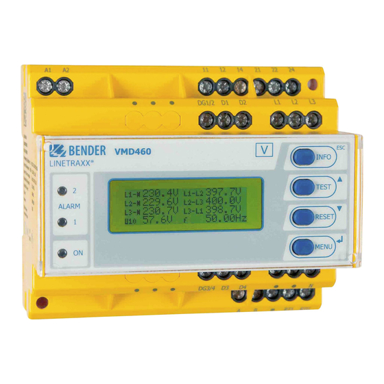
5. Operation and configuration 5.1 Getting to know the user interface VMD460 LINETRAXX® Element Function Power On LED, green; lights when the power supply is available and the device is in operation; flashes in case of system fault alarm (external watchdog) Generation system disconnected: ALARM1 Both LEDs light (yellow) in the case of limit value violation... -
Page 30: Various Displays
Operation and configuration Standard display: Toggling between standard display and Info device information Menu display: To exit the parameter setting menu without storing; to go to the next higher menu level Standard display: A manual test is carried out using the TEST test button (>... -
Page 31: Info Display
Operation and configuration 5.2.2 Info display Device-specific information is available in the info display. VMD460-NA 22.02.13 12:34 Software: Dxxx Date:18.02.13 Fig. 5.2: Info display For detailed information refer to page 33. 5.2.3 Alarm display Type and source of alarms are indicated on the alarm display in plain text for- mat. -
Page 32: Toggling Between The Displays
Operation and configuration 5.2.5 Toggling between the displays You can toggle between the different displays by using the four device but- tons. Depending on the type of display (standard display, alarm display, menu display, info display), the meaning of the buttons is different. The picture be- low illustrates which button is to be pressed for accessing the individual dis- play. -
Page 33: Info Button
Operation and configuration 5.3 INFO button Device information in clear text format (Info display) can be called up with the "INFO" button. For this purpose press the "INFO" button in the standard dis- play once. Scroll through the individual lines using the arrow buttons Device type Current date, current time Address BMS-Bus... -
Page 34: Alarm/Meas. Values
Operation and configuration 5.4.1 Alarm/meas. values For detailed information about the value, select the "Alarm/meas. values" menu item (select the menu item using Select the individual entries by means of the buttons. Exit 1. U(1-N): Value 2. U(2-N): Value 3. U(3-N): Value 4. -
Page 35: History
Operation and configuration Measuring channel 15: Indicates the total time passed during the self test between the simulation of 0 V on L1 to the disconnection of coupling switch 1. Measuring channel 16: Indicates the total time passed during the self test between the simulation of 0 V on L1 to the disconnection command for coupling switch 1. - Page 36 Operation and configuration History No. 297 Undervoltage Min. 21 V/max.198 V Addr.:2 Chan.:1 Fig. 5.7: History (detail) Line 1: Data record number Line 2: Alarm status and alarm text (e.g. undervoltage, transformer er- ror,…) = no alarm = alarm, fault Line 3: Minimum and maximum measured value after the occurrence of an alarm Line 4: RS-485 address and measuring channel of the device sending...
-
Page 37: Settings
Once a valid password has been entered, access will be granted to settings in all menus (except the Service menu) until menu mode is exited. If you can't remember your password, contact the Bender Service. In principle, all preset response values can be changed, if this should be nec- essary. -
Page 38: System
Operation and configuration 5.4.4 System The following table gives an overview of the menu structure. The values can be changed in the third level of the menu (column "twice ") using There are two different ways to exit the system menu: Save and exit: „... - Page 39 Operation and configuration Menu: System once twice 4. Password Exit * * * Toggling between positions with Password Status 5. Interface 1…90 Exit 1: MASTER Address 2…90: Slave 6. Alarm addresses Exit 1…150: off/on Address xxx 7. TEST Cancel Test will be carried out TEST 8.
-
Page 40: Info
Operation and configuration 5.4.5 Info The following table gives an overview of the information to be called up. Scroll through the individual lines using the arrow buttons Device type Current date, current time Address BMS-Bus Software version (measurement technique) Date of software (measurement technique) Software version (display) Date of software (display) Manufacturer of the device... -
Page 41: Maintenance
6. Maintenance Repeat test of the trigger circuit by the system operator The system operator must ensure that the equipment required for parallel operation with the low-voltage network is always in proper technical condi- tion. To this end, it is required to have an electrically skilled person check the protective devices for proper functioning at regular intervals. - Page 42 Maintenance VMD460-NA_D00001_01_M_XXEN/08.2013...
-
Page 43: Selectable Default Settings
7. Selectable default settings Response values for NS protection may only be changed in consultation with the system operator! The following standards are implemented in the factory settings of the VMD460-NA: VDE-AR-N 4105 CEI 0-21 BDEW guideline ... -
Page 44: Vde-Ar-N 4105
Selectable default settings 7.1 VDE-AR-N 4105 4105 Menu : Factory once twice Settings setting Exit General Exit CEI021 norm 4105 1 AC coupling 3N AC 3N AC 3 AC U(L-N) 50…250 V U(L-N) 230 V U(L-L) 87…433 V 1…300 s t SHORT INT. - Page 45 Selectable default settings 4105 Menu : Factory once twice Settings setting Frequency Exit f> off/50.00…65.00 Hz 51.50 Hz f (ON) MAX off/50.00…65.00 Hz 50.05 Hz f (ON) MIN off/45.00…60.00 Hz 47.50 Hz f< off/45.00…60.00 Hz 47.50 Hz df/dt Exit Mode off/on Resp.
-
Page 46: Cei 0-21
Selectable default settings 4105 Menu : Factory once twice Settings setting Digital Input Exit D1: N/C D2: N/C Relay mode N/C; N/O; off D3: off* D4: off* * not used in VDE-AR-N 4105 7.2 CEI 0-21 CEI 0-21 menu: Factory once twice Settings... - Page 47 Selectable default settings CEI 0-21 menu: Factory once twice Settings setting Voltage Exit U>> (59.S2) off/100…130 % 115 % T (OFF) (59.S2) 0.04…30.0 s 200 ms U> (59.S1) off/100…130 % 110 % T (OFF) (59.S1) 0.04…30.0 s 3.00 s U< (27.S1) off/1…100 % 85 % T (OFF)(27.S1)
- Page 48 Selectable default settings CEI 0-21 menu: Factory once twice Settings setting df/dt Exit Mode Resp. value 0.1…9.9 Hz/s 1.0 Hz/s Hysteresis 1.0…50 % Meas. window 0.05…1 s 200 ms T (OFF) 0.04…30.0 s 100 ms T (ON) 1 s…60 min 60 s Asymmetry Exit...
-
Page 49: Bdew-Guideline
Selectable default settings 7.3 BDEW-guideline BDEW menu: Factory once twice Settings setting Exit General Exit CEI021, 4105, BDEW, norm C10/11 1 AC coupling 3N AC 3N AC 3 AC U(L-N) 50…250 V U(L-N) 230 V U(L-L) 87…433 V t (ON) 1 s…60 min 30 s Remote Trip... - Page 50 Selectable default settings BDEW menu: Factory once twice Settings setting Frequency Exit f>> off/50.00…65.00 Hz off T(OFF) 0.04…30.0 s 100 ms f> off/50.00…65.00 Hz 51.50 Hz T (OFF) 0.04…30.0 s 100 ms f (ON) MAX off/1…65 Hz 50.05 Hz f (ON) MIN off/45.00…60.00 Hz 47.50 Hz f<...
- Page 51 Selectable default settings BDEW menu: Factory once twice Settings setting Asymmetry Exit Mode off/on Resp. value 1.0…50.0 % 5.0 % Hysteresis 1.0…50.0 % 20.0 % T (OFF) 0.04…30.0 s 100 ms Relay Exit K1: N/C Relay mode K2: N/C Digital Input* Exit D1: off D2: off...
- Page 52 Selectable default settings 7.4 C10/11 C10/11 menu: Factory once twice Settings setting Exit General Exit CEI021, 4105, BDEW, norm C10/11 1 AC coupling 3N AC 3N AC 3 AC U(L-N) 50…250 V U(L-N) 230 V U(L-L) 87…433 V t SHORT INT. 1 s…60 min t (ON) SHORT INT.
- Page 53 Selectable default settings C10/11 menu: Factory once twice Settings setting Voltage Exit U>> off/100…130 % 115 % T (OFF) 0.04…30.0 s 100 ms U> off/100…130 % 110 % T (OFF) 0.04…30.0 s 100 ms U (ON) MAX off/100…130 % 110 % U (ON) MIN off/1…100% 85 %...
- Page 54 Selectable default settings C10/11 menu: Factory once twice Settings setting df/dt Exit Mode off/on Resp. value 0.1…9.9 Hz/s 1.0 Hz/s Hysteresis 1.0…50.0 % 20.0 % Meas. window 0.05…1 s 200 ms T (OFF) 0.04…30.0 s 100 ms T (ON) 1 s…60 min 60 s Asymmetry Exit...
-
Page 55: Technical Data Vmd460-Na
8. Technical data VMD460-NA ( )* = factory setting Insulation coordination acc. to IEC 60664-1/IEC 60664-3 Rated insulation voltage ............................400 V Overvoltage category..............................III Rated impulse voltage/pollution degree......................6 kV/2 Protective separation (reinforced insulation) between....(A1, A2) - (L1, L2, L3, N) - (11, 12, 14, 21, 22, 24) - Page 56 Technical data VMD460-NA Recording of measurement values, condition for connection L-N, L-L ................................0…1.3 < .................................. 45…60 Hz > .................................. 50…65 Hz Recording of measurement value, condition for disconnection L-N, L-L ................................0…1.3 < .................................. 45…60 Hz > .................................. 50…65 Hz df/dt................................0.1…9,9 Hz/s...
- Page 57 Technical data VMD460-NA History memory for the last 300 messages ............... per data record measured values Password.............................on/off / 0…999 (off*) Switching elements Number of changeover contacts ....................... 2 x 1 (K1, K2) Operating mode......................N/C operation / N/O operation Electrical service life under rated operating conditions............10.000 switching operations Contact data acc.
- Page 58 Technical data VMD460-NA Other Operating mode ..........................continuous operation Mounting ..............................any position Degree of protection, built-in components (DIN EN 60529) ................. IP30 Degree of protection, terminals (DIN EN 60529) ....................IP20 Enclosure material ............................polycarbonate Flammability class ............................UL94 V-0 DIN rail mounting acc. to..........................IEC 60715 Screw fixing .........................
-
Page 59: Standards, Approvals And Certifications
Technical data VMD460-NA 8. 1 Standards, approvals and certifications The VMD460-NA fulfils the requirements of the following standards: VDE-AR-N 4105 (Technical minimum requirements for the connection to and parallel operation with low-voltage distribution networks) CEI 0-21 (Regola tecnica di riferimento per la connessione di utenti ... - Page 60 Technical data VMD460-NA VMD460-NA_D00001_01_M_XXEN/08.2013...
-
Page 61: Index
INDEX - Info 31 - Menu 31 - Toggling between the displays 32 Alarm display 31 Automatic self test 14 Electrically skilled person 11 Enter button 30 Button - INFO 33 Factory setting 17 - MENU 33 - RESET 30 - TEST 30 How to use this manual 7 Calculating the average value of overvolt-... - Page 62 MENU button 33 - Wiring diagram 22 Menu display 31 Mounting clip for screw mounting 59 Wiring diagram 22 Work activities on electrical installations 12 Network and system protection 11 workshops 9 Operation and configuration 29 Ordering information 59 Password protection 17 Preset function 14 Remote-Trip 15 RESET button 30...
- Page 64 D0000101MXXEN Bender GmbH & Co. KG Londorfer Str. 65 • 35305 Gruenberg • Germany Postfach 1161 • 35301 Gruenberg • Germany Tel.: +49 6401 807-0 Fax: +49 6401 807-259 E-Mail: info@bender-de.com Web: http://www.bender-de.com...
Need help?
Do you have a question about the VMD460-NA and is the answer not in the manual?
Questions and answers