
Related Manuals for Bender VMD420-DM


Summary of Contents for Bender VMD420-DM
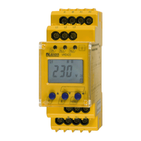
- Page 1 Manual VMD420-DM Voltage and frequency monitor for monitoring of 3(N)AC systems up to 0…500 V for undervoltage and overvoltage and under and overfrequency Software version: D238 V2.2x VMD420-DM_D00227_01_M_XXEN/07.2015...
- Page 2 Bender GmbH & Co. KG Londorfer Str. 65 • 35305 Gruenberg • Germany Postfach 1161 • 35301 Gruenberg • Germany Tel.: +49 6401 807-0 Fax: +49 6401 807-259 Email: info@bender.de www.bender.de © Bender GmbH & Co. KG All rights reserved.
-
Page 3: Table Of Contents
Table of Contents 1. How to use this documentation effectively ..........5 2. Safety ........................7 General ......................... 7 Intended use ...................... 7 Skilled person ....................7 Safety information on work activities on electrical installations ..8 3. Function ......................9 Device features .................... - Page 4 Table of Contents Wiring of the device ..................18 Commissioning preset function/factory setting ........ 19 5. Operation and setting .................. 21 Getting to know the user interface ............21 Understanding of standard display indications ......... 22 Getting to know keys and key functions ..........23 Querying values .....................
-
Page 5: How To Use This Documentation Effectively
1. How to use this documentation effectively This manual is intended for experts in electrical engineering and electronics! In order to make it easier for you to find specific text passages or references in this manual and for reasons of comprehensibility, important information is emphasized by symbols. - Page 6 How to use this documentation effectively VMD420-DM_D00227_01_M_XXEN/07.2015...
-
Page 7: Safety
2. Safety 2.1 General In addition to this manual, the documentation of the device includes a docu- ment entitled "Important safety instructions for Bender products“. 2.2 Intended use The voltage monitor VMD420 monitors 3(N)AC systems in the frequency range 15…460 Hz for undervoltage, overvoltage, underfrequency and over- frequency. -
Page 8: Safety Information On Work Activities On Electrical Installations
Safety 2.4 Safety information on work activities on electrical installations Danger of electric shock! Unprofessional work activities on electrical installations may result in a threat of danger to life and limb! DANGER All work activities on electrical installations as well as installation activities, commissioning activities and work activities with the device in operation may only be carried out by electrically skilled persons! -
Page 9: Function
3. Function 3.1 Device features The VMD420 requires a separate supply voltage U Monitoring for undervoltage and overvoltage and underfrequency and overfrequency in 3(N)AC systems of AC 0…500 V / 0…288 V Asymmetry, phase failure and phase sequence monitoring ... -
Page 10: Preset Function
+ 1 Hz Response value underfrequency ( < f) at 16.7 Hz, 50 Hz, 60 Hz: f - 1 Hz Response value underfrequency ( < f) at 400 Hz: f - 1 Hz Preset VMD420-DM Preset Response Response Measuring principle... -
Page 11: Automatic Self Test
3.2.4 Functional faults If an internal malfunction occurs, all three LEDs flash. An error code will appear on the display (E01…E32). In such a case please contact the Bender Service. 3.2.5 Fault memory The fault memory can be activated, deactivated or can be set to continuous mode (con). -
Page 12: Start-Up Delay T
Only the output that has been selected via software may be connected: Output signal Purpose of use DC 0…400 μA Current output for Bender measuring instruments of the 96.. series DC 0/4…20 mA Standardised current output with selectable current ranges DC 0…10 V Standardised voltage signal... -
Page 13: Menu Item Ana For Interface Configuration
Function 3.2.11 Menu item AnA for interface configuration Display Measured variable 100 % value < L1L2L3 500 V lowest voltage of all 3 adjustable in the range of 7…500 V phases > L1L2L3 500 V highest voltage of all 3 adjustable in the range of 7…500 V phases 500 V... - Page 14 Function VMD420-DM_D00227_01_M_XXEN/07.2015...
-
Page 15: Installation, Connection And Commissioning
4. Installation, connection and commissioning Danger of electric shock! Make sure that the installation area is disconnected from any electrical source before starting installation works and that the nominal voltage and supply voltage specified in the DANGER relevant data sheet are observed! 4.1 Fast commissioning for = 400 V, 50 Hz If you are already familiar with voltage monitors, you can reduce the time for... - Page 16 Installation, connection and commissioning 4. The currently measured phase-to-phase voltage between L1 and L2 appears on the display. Use the UP and DOWN keys to query other parameters: – phase-to-phase voltage L2, L3 – phase-to-phase voltage L1, L3 – asymmetry –...
-
Page 17: Installing The Device
Installation, connection and commissioning 4.2 Installing the device 36 mm Fig. 4.1: Dimension diagram and drawing for screw fixing 4.2.1 DIN rail mounting 1. Open the front plate cover at the lower part marked by an arrow. 2. Snap the rear mounting clip of the device into place in such a way that a safe and tight fit is ensured. -
Page 18: Wiring Of The Device
Installation, connection and commissioning 4.3 Wiring of the device Connect the device according the wiring diagram. µA mA V Connect the conductor to the push-wire terminals according to the drawing. Terminal Connections Connection to the supply A1, A2 voltage U Connection to the system to L1, L2, L3, (N) be monitored... -
Page 19: Commissioning Preset Function/Factory Setting
Installation, connection and commissioning 4.4 Commissioning preset function/factory setting Material damage by improper connection of the device! Prior to commissioning make sure that the device is properly connected! CAUTION After connecting a brand-new VMD420… to a standard system of U = 400 V 50 Hz, the response values are automatically set by the internal preset function: Overvoltage = 440 V (400 V + 10 %) (50 Hz + 1 Hz) - Page 20 Installation, connection and commissioning Factory setting Hysteresis U: Underfrequency < Hz Overfrequency > Hz Hysteresis frequency (Hys Hz): 0.2 Hz Fault memory M: Interface type 0…20 mA 100 % reference: U > 500 V Asymmetry: 30 % Phase sequence monitoring: Start-up delay: t = 0 s Method of measurement:...
-
Page 21: Operation And Setting
5. Operation and setting 5.1 Getting to know the user interface POWER ON LED: Lights up when voltage is available and when the device is in operation. LED ALARM 1: Lights when the response value of overvoltage is exceeded. LED ALARM 2: Lights when the response value of undervoltage is exceeded. -
Page 22: Understanding Of Standard Display Indications
Operation and setting 5.2 Understanding of standard display indications Fig. 5.2: Standard displays DISPLAY LINE CONDUCTORS DISPLAY TYPE OF VOLTAGE: L1-L3: Displays the type of voltage. Displays active line conduc- PASSWORD PROTECTION EN- tors. ABLED: DISPLAY ASYMMETRY: Indicates that password pro- Displays the asymmetry value tection is activated. -
Page 23: Getting To Know Keys And Key Functions
Operation and setting 5.3 Getting to know keys and key functions The following table shows the functions of the keys for navigation on the dis- play, navigation through the menu and parameter setting. From "Chapter 5.4 Querying values" onwards, only the respective key symbols are used for que- rying values. -
Page 24: Querying Values
Operation and setting 5.4 Querying values By default, the display shows the phase-to-phase voltage between L1 and L2. By pressing the UP and DOWN key, the phase-to-phase voltage between L1 and L3, L2 and L3 as well as asymmetry, system frequency and phase sequence can be queried The flashing elements in the display indications below are highlighted as grey-shaded fields. -
Page 25: Starting The Self Test Manually
Operation and setting Query Display indication 7. Query asymmetry 8. Change display indication 9. Query system frequency 10. Change display indication 11. Query phase sequence 5.5 Starting the self test manually The self test described in "Chapter 3.2.2 Automatic self test" can also be start- ed manually. -
Page 26: Clearing The Fault Memory
Operation and setting 5.6 Clearing the fault memory The device utilises an erasable fault memory. In order to clear the fault memory: Keep the UP key pressed for more than 1.5 seconds. 5.7 Calling up or leaving the menu In order to call up the menu: Keep the ENTER key pressed for more than 1.5 seconds. - Page 27 Operation and setting Description/parameter setting Menu item/Key to call 1. Press the UP/DOWN key to select the next menu item. Configuring the fault memory and the analogue interface: Fault memory: activate/deactivate or select con mode Selection of the type of the analogue interface: ...
-
Page 28: Carrying Out Settings In The Menu Item Al
Operation and setting Description/parameter setting Menu item/Key to call Query stored alarm values 6. Press the UP/DOWN key to select the next menu item. Move to the next higher menu level (return) 5.8.2 Carrying out settings in the menu item AL 1. - Page 29 Operation and setting Change dis- Menu item Select submenu Activate/deacti- Change/save play parame- item vate parameters param. ter value 3. Set the response value for overvoltage 4. Select sub- menu item 5. Set the hys- teresis for voltage response val- 6.
- Page 30 Operation and setting Change dis- Menu item Select submenu Activate/deacti- Change/save play parame- item vate parameters param. ter value 9. Set the response value for underfre- quency 10. Select sub- menu item 11. Set the response value for overfre- quency 12.
- Page 31 Operation and setting Change dis- Menu item Select submenu Activate/deacti- Change/save play parame- item vate parameters param. ter value 15. Set the response value for phase sequence 16. Select sub- menu item 17. Return to menu item VMD420-DM_D00227_01_M_XXEN/07.2015...
-
Page 32: Carrying Out Settings In The Menu Item Out
Operation and setting 5.8.3 Carrying out settings in the menu item out 1. Select menu item out. Carry out parameter change as illustrated below. 2. Keep the ENTER key pressed for more than 1.5 seconds to return to the menu item level after parameter change. Activate/deacti- Change dis- Menu item... - Page 33 Operation and setting Activate/deacti- Change dis- Menu item Select submenu Change/save vate/change par- play parame- item param. ter value 3. Select sub- menu item 4. Select cur- rent output 0…20 mA 5. Change parameter 6. Select cur- rent output 0…400 μA 7.
- Page 34 Operation and setting Activate/deacti- Change dis- Menu item Select submenu Change/save vate/change par- play parame- item param. ter value 12. Set the 100 % reference of the analogue output to: highest volt- age of all 3 phases 13. Change parameter 14.
- Page 35 Operation and setting Activate/deacti- Change dis- Menu item Select submenu Change/save vate/change par- play parame- item param. ter value 18. Set the 100 % reference to: response value over- voltage of all 3 phases The activation of AL (L1 L2 L3) 19.
-
Page 36: Carrying Out Settings In The Menu Item T
Operation and setting 5.8.4 Carrying out settings in the menu item t 1. Select menu item t 2. Carry out parameter change as illustrated below. 3. Keep the ENTER key pressed for more than 1.5 seconds to return to the menu item level after parameter change. -
Page 37: Carrying Out Settings In The Menu Item Set
Operation and setting 5.8.5 Carrying out settings in the menu item SEt 1. Select menu item SEt. 2. Carry out parameter change as illustrated below. 3. Keep the ENTER key pressed for more than 1.5 seconds to return to the menu item level after parameter change. - Page 38 Operation and setting Activate/deacti- Change dis- Menu item Select submenu Change/save vate/change par- play parame- item param. ter value 4. Changing the password 5. Disable pass- word protec- tion 6. Select sub- menu item VMD420-DM_D00227_01_M_XXEN/07.2015...
- Page 39 Operation and setting Activate/deacti- Change dis- Menu item Select submenu Change/save vate/change par- play parame- item param. ter value 7. Re-establish factory set- ting The text "run“ will appear on the display and the device will automatically reset to factory setting.
-
Page 40: Querying Information In Menu Item Inf
Operation and setting Activate/deacti- Change dis- Menu item Select submenu Change/save vate/change par- play parame- item param. ter value 10. Select sub- menu item 11. System menu locked 12. Select sub- menu item 13. Return to menu item 5.8.6 Querying information in menu item INF 1. -
Page 41: Querying And Clearing Fault Memory In The Menu Item His
Operation and setting 5.8.7 Querying and clearing fault memory in the menu item HIS 1. Select menu item HIS. 2. Change parameters according to table. 3. Keep the ENTER key pressed for more than 1.5 seconds to return to the menu item level after parameter change. - Page 42 Operation and setting Fault indication /Submenu Menu item HIS item 9. Query frequency faults 10. Select fault indication 11. Query phase faults 12. Select fault indication 13. To clear the fault memory 14. Select fault indication 15. Return to menu item HiS VMD420-DM_D00227_01_M_XXEN/07.2015...
-
Page 43: Technical Data
(N, L1, L2, L3) - (A1, A2), (M+, μA, mA, V) ..................... 3.32 kV (N, L1, L2, L3) - (M+, μA, mA, V) ........................2.21 kV (A1, A2) - (M+, μA, mA, V) ..........................2.21 kV Supply voltage VMD420-DM-1: Supply voltage U ......................AC 16…72 V / DC 9.6…94 V Frequency range U ........................... - Page 44 Technical data Preset function for 3 AC measurement: Undervoltage< U (0.85 )* for = 400 V/ 208 V ................340 V / 177 V Overvoltage > U (1.1 )* for = 400 V/ 208 V ................440 V / 229 V Preset function for 3(N)AC measurement: Undervoltage <...
- Page 45 Technical data Operating uncertainty: voltage in the range of 15…460 Hz.............. ±3 %, ±2 digit Operating uncertainty: frequency in the range of 15…460 Hz ............±0.2 %, ±1 digit History memory (HiS) for the first alarm value..............data record measured values Password ............................
- Page 46 Technical data Connection Connection ........................screw-type terminals Connection properties: Rigid/ flexible ..................... 0.2…4 / 0.2…2.5 mm / AWG 24…12 Multi-conductor connection (2 conductors with the same cross section): Rigid, flexible........................0.2…1.5 / 0.2…1.5 mm Stripping length ............................8…9 mm Tightening torque ............................ 0.5…0.6 Nm Connection ........................
-
Page 47: Current And Voltage Curves Of The Analogue Interface
Technical data 6.2 Current and voltage curves of the analogue interface Current output 0/4…20 mA Current output 0…400 μA Current output 0…10 V VMD420-DM_D00227_01_M_XXEN/07.2015... -
Page 48: Standards, Approvals And Certifications
Technical data 6.3 Standards, approvals and certifications 6.4 Ordering information Nominal voltage Supply voltage U Device type Art. No. VMD420-DM-1 3(N)AC 0…500 V/ AC 16…72 V / DC 9.6 (push-wire 288 V V…94 V B 7301 0017 DC, 15…460 Hz terminals) 15…460 Hz... -
Page 49: Index
INDEX Automatic self test 11 Manual self test 11 Menu item AL 28 Menu item HIS 41 currently measured values Menu item INF 40 - asymmetry 24 Menu item OUT 32 - phase sequence 24 Menu item SET 37 - phase-to-phase voltage 24 Menu item t 36 - rated frequency 24 Menu, call up 26... - Page 50 Technical data 43 To clear the fault memory 26 User interface 21 Wiring diagram 18 Work activities on electrical installations 8 VMD420-DM_D00227_01_M_XXEN/07.2015...
- Page 52 Bender GmbH & Co. KG Londorfer Str. 65 • 35305 Gruenberg • Germany Postfach 1161 • 35301 Gruenberg • Germany Tel.: +49 6401 807-0 Fax: +49 6401 807-259 Email: info@bender.de www.bender.de Photos: Bender archives...
Need help?
Do you have a question about the VMD420-DM and is the answer not in the manual?
Questions and answers