Table of Contents
Advertisement
Quick Links
Advertisement
Table of Contents

Related Manuals for Bender VME421H


Summary of Contents for Bender VME421H
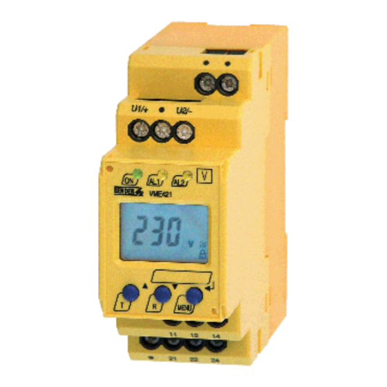
- Page 1 Manual VME421H Voltage and frequency monitor for monitoring AC/DC systems for undervoltage, overvoltage, underfrequency and overfrequency Software version VME421H-D-1: D236 V2.2x Software version VME421H-D-2: D237 V2.2x VME421H_D00141_01_M_XXEN/06.2016...
- Page 2 Bender GmbH & Co. KG P.O. Box 1161 • 35301 Gruenberg • Germany Londorfer Strasse 65 • 35305 Gruenberg • Germany Tel.: +49 6401 807-0 • Fax: +49 6401 807-259 E-Mail: info@bender.de • www.bender.de © Bender GmbH & Co. KG All rights reserved.
-
Page 3: Table Of Contents
Table of Contents 1. Important information ..................5 How to use this manual ................. 5 Technical support: service and support ........... 6 1.2.1 First level support ..................... 6 1.2.2 Repair service ..................... 6 1.2.3 Field service ......................7 Training courses ....................8 Delivery conditions .................. - Page 4 5.6.10 Device information query ................39 5.6.11 History memory query ................. 39 Preset function/ factory setting ............... 40 Commissioning ....................40 6. Technical data VME421H… ................. 41 Ordering information ................... 45 Standards, approvals and certifications ..........45 INDEX ........................47...
-
Page 5: Important Information
1. Important information 1.1 How to use this manual This manual is intended for qualified personnel working in electrical engineering and electronics! Always keep this manual within easy reach for future reference. To make it easier for you to understand and revisit certain sections in this man- ual, we have used symbols to identify important instructions and information. -
Page 6: Technical Support: Service And Support
Important information This manual has been compiled with great care. It might nevertheless contain errors and mistakes. Bender cannot accept any liability for injury to persons or damage to property resulting from errors or mistakes in this manual. 1.2 Technical support: service and support For commissioning and troubleshooting Bender offers you: 1.2.1... -
Page 7: Field Service
Important information Bender GmbH, Repair-Service, Londorfer Str. 65, 35305 Gruenberg 1.2.3 Field service On-site service for all Bender products Commissioning, configuring, maintenance, troubleshooting of Bender products Analysis of the electrical installation in the building (power quality test, ... -
Page 8: Training Courses
ZVEI (Zentralverband Elektrotechnik- und Elektronikindustrie e. V.) (German Electrical and Electron- ic Manufacturer's Association) also applies. Sale and delivery conditions can be obtained from Bender in printed or elec- tronic format. 1.5 Inspection, transport and storage Inspect the dispatch and equipment packaging for damage, and compare the contents of the package with the delivery documents. -
Page 9: Warranty And Liability
Important information 1.6 Warranty and liability Warranty and liability claims in the event of injury to persons or damage to property are excluded if they can be attributed to one or more of the follow- ing causes: Improper use of the device. ... -
Page 10: Disposal
13 August 2005 must be taken back by the manufacturer and disposed of properly. For more information on the disposal of Bender devices, refer to our homepage at www.bender-de.com -> Service & support. -
Page 11: Safety Instructions
2. Safety instructions 2.1 General safety instructions Part of the device documentation in addition to this manual is the enclosed "Safety instructions for Bender products". 2.2 Work activities on electrical installations Only qualified personnel are permitted to carry out the work necessary to install, commission and run a device or system. -
Page 12: Intended Use
Safety instructions 2.3 Intended use The voltage monitor VME421H monitors AC/DC systems in the frequency ran- ge of DC/15…460 Hz for undervoltage, overvoltage, underfrequency or over- frequency. Device variant -1 is suitable for the nominal voltage range U 9.6…150 V, device variant -2 for U = 70…300 V. -
Page 13: Function
3. Function 3.1 Device features Undervoltage and overvoltage monitoring of AC/DC systems in the frequency range DC/15…460 Hz device variant -1: 9,6…150 V device variant -2: 70…300 V Preset function: Automatic response value setting for undervoltage and overvoltage, <... -
Page 14: Preset Function
Response value underfrequency ( < f) at 16.7 Hz, 50 Hz, 60 Hz: f - 1 Hz Response value underfrequency ( < f) at 400 Hz: f - 1 Hz Preset VME421H-D-1 / VME421H-D-2 Preset Response value Response value Device operating range <... -
Page 15: Automatic Self Test
3.2.4 Malfunction If an internal functional fault occurs, all three LEDs flash. An error code will ap- pear on the display (E01…E32). In such a case please contact the Bender Service. 3.2.5 Fault memory The fault memory can be activated, deactivated or can be set to continuous mode (con). -
Page 16: Assigning Alarms To The Alarm Relays K/1K2
3.2.8 Password protection (on, OFF) With the password protection activated (on), settings are only possible after entering the correct password (0…999). If you cannot operate your device because you cannot remember your pass- word, please contact info@bender-service.de. VME421H_D00141_01_M_XXEN/06.2016... -
Page 17: Factory Setting Fac
Function 3.2.9 Factory setting FAC After activating the factory setting, all settings previously changed are reset to delivery status. In addition, the preset function allows automatic adaptation of the response values in relation to the nominal voltage U 3.2.10 Erasable history memory The first alarm value that occurs will be stored in this memory. -
Page 18: Starting A Device Using A Simulated Alarm S.al
Function 3.2.12 Starting a device using a simulated alarm S.AL If the menu item S.AL has been activated in the out menu, K1 resp. K2 switches back to the alarm state once the supply voltage is applied. This alarm state is maintained for the set duration t + t . -
Page 19: Installation And Connection
4. Installation and connection Only qualified personnel are permitted to carry out the work necessary to install, commission and run a device or system. Risk of electrocution due to electric shock! Touching live parts of the system carries the risk of: An electric shock ... - Page 20 Installation and connection 1. DIN rail mounting: Snap the rear mounting clip of the device into place in such a way that a safe and tight fit is ensured. Screw fixing: Use a tool to move the rear mounting clips (a second mounting clip is required, see ordering information) to a position that it projects bey- ond the enclosure.
-
Page 21: Operation And Setting
4. When the conditions 1, 2 and 3 are satisfied, you can connect the vol- tage monitor to the system to be monitored according to the wiring diagram (page 20). The following predefined response values will be set automatically: VME421H-D-2 Preset Response value Response value operating range <... -
Page 22: Display Elements In Use
Operation and setting page 40 provides a summary of all factory settings. If you want to reset the voltage monitors to factory settings, refer to page 38. 5.2 Display elements in use The meaning of the display elements in use is listed in detail in the table below. -
Page 23: Function Of The Operating Elements
Operation and setting 5.3 Function of the operating elements Elemen Device front Function Power On LED, green Menu item LEd deactivated: AL1 AL2 LED Alarm 1 lights (yellow): AL1, Response value > U reached LED Alarm 2 lights (yellow): Res- ponse value <... -
Page 24: Menu Structure
Operation and setting Elemen Device front Function MENU, MENU key (> 1.5 s): Starting the menu mode; Enter key (< 1.5 s): Confirm menu item, submenu item and value. Enter key (> 1.5 s): Back to the next higher menu level. 5.4 Menu structure All adjustable parameters are listed in the columns menu item and adjustable parameters. - Page 25 Operation and setting Menu Activati Menu Adjustable parameter Menu item Fault memory (on, con, off ) (output control) Operating mode K1 (n.o.) Operating mode K2 (n.c.) LEDs signal relay in alarm state 1 Err Device error at K1 r1 < U Undervoltage K1 r1 >...
-
Page 26: Display In Standard Mode
Operation and setting Menu Activati Menu Adjustable parameter Menu item Parameter setting via pass- word (device con- trol) Re-establish factory set- tings Manual preset Function blocked Display hard / software version History memory for the first alarm value, erasable 5.5 Display in standard mode By default, the display indicates the voltage applied between the terminals U1/+ and U2/-. -
Page 27: Display In Menu Mode
Operation and setting 5.6 Display in menu mode 5.6.1 Parameter query and setting: Overview Menu item Adjustable parameter Interrogate and adjust response values: – Undervoltage: < U (AL2) – Overvoltage: > U (AL1) – Hysteresis of the voltage response values: Hys U –... - Page 28 Operation and setting Menu structure VME421H_D00141_01_M_XXEN/06.2016...
- Page 29 Operation and setting Parameter settings An example is given below on how to change the alarm response value for overvoltage > U. Proceed as follows: 1. Press the MENU/Enter key for more than 1.5 seconds. The flashing short symbol AL appears on the display. 2.
-
Page 30: Setting The Response Values For Undervoltage, Overvoltage And Hysteresis
Operation and setting 5.6.2 Setting the response values for undervoltage, overvoltage and hysteresis Set the response value at which an alarm is to be issued. Setting the undervoltage response value < U Setting the overvoltage response value> U Setting the hysteresis of the voltage response values VME421H_D00141_01_M_XXEN/06.2016... -
Page 31: Setting The Response Values For Underfrequency, Overfrequency And Hysteresis
Operation and setting 5.6.3 Setting the response values for underfrequency, overfrequency and hysteresis Setting the underfrequency response value < Hz Setting the overfrequency response value > Hz VME421H_D00141_01_M_XXEN/06.2016... -
Page 32: Setting The Fault Memory And Operating Principle Of The Alarm Relays
Operation and setting Setting the hysteresis of the frequency response values 5.6.4 Setting the fault memory and operating principle of the alarm relays Deactivating the fault memory Setting the alarm relay K1 to N/C operation (n.c.) VME421H_D00141_01_M_XXEN/06.2016... - Page 33 Operation and setting Setting the alarm relay K2 to N/O operation (n.o.) LEDs AL1/AL2 are intended to indicate the alarm state of K1/K2 VME421H_D00141_01_M_XXEN/06.2016...
-
Page 34: Assigning Alarm Categories To The Alarm Relays
Operation and setting 5.6.5 Assigning alarm categories to the alarm relays Undervoltage, overvoltage, underfrequency, overfrequency and device-rela- ted error messages of the voltage relay can be assigned to the alarm relays K1 (r1, 1) and K2 (r2, 2. K1 is set at the factory to signal an alarm in the event of overvoltage, and K2 is set to signal an alarm in the event of undervoltage. - Page 35 Operation and setting Alarm relay 1: Deactivating the category overvoltage When an alarm relay (K1/K2) has been deactivated via the menu, an alarm will not be signalled by the respective changeover contact! An alarm will only be indicated by the respective alarm LED (AL1/AL2)! CAUTION This only applies to the out menu setting LEd = off!
-
Page 36: Setting The Time Delay
Operation and setting 5.6.6 Setting the time delay Use this segment to set a response delay t (0…300 s) for K1, t (0…300 s) for K2, a start-up delay t (0…300 s) when starting the device, as well as a common release delay t (0…300 s) for K1, K2. -
Page 37: Factory Setting And Password Protection
Operation and setting 5.6.7 Factory setting and password protection Use this menu to activate the password protection, to change the password or to deactivate the password protection. In addition, you can reset the device to its factory settings. a) Activating the password protection b) Changing the password VME421H_D00141_01_M_XXEN/06.2016... -
Page 38: Restoring Factory Settings
Operation and setting c) Deactivating the password protection 5.6.8 Restoring factory settings VME421H_D00141_01_M_XXEN/06.2016... -
Page 39: Manual Activation Of The Preset Function
Operation and setting 5.6.9 Manual activation of the preset function 5.6.10 Device information query This function is used to query the hardware (d…) and software (1.xx) versions. After activating this function, data will be displayed as a scrolling text. Once one pass is completed, you can select individual data sections using the Up/ Down keys. -
Page 40: Preset Function/ Factory Setting
0, Off 5.8 Commissioning Prior to commissioning, check proper connection of the voltage monitor. After connecting a brand-new VME421H-D-2 to a standard system of U = 230 V 50 Hz, the response values are automatically set by the internal preset function:... -
Page 41: Technical Data Vme421H
................. none (internally supplied by U : 70…300 V) Power consumption ............................≤ 6 VA Measuring circuit Measuring range (r.m.s.) (VME421H-D-1) ................... AC / DC 0…150 V Measuring range (r.m.s.) (VME421H-D-2) ..................AC / DC 0…300 V Rated frequency f ..........................DC, 15…460 Hz Frequency range ........................... - Page 42 Discharging time energy backup on power failure (VME421H-D-1) ..............≥ 3 s Discharging time energy backup on power failure (VME421H-D-1) ........≥ 2.5 s at f 42 Hz < Discharging time energy backup on power failure (VME421H-D-2) ..........≥ 4 s at DC 70 V VME421H_D00141_01_M_XXEN/06.2016...
- Page 43 Technical data VME421H… .............................. ≥ 6 s at DC 80 V / AC 70 V Charging time energy backup (VME421H-D-1) ....................≤ 60 s Charging time energy backup (VME421H-D-2) ....................≤ 120 s Recovery time t .............................. ≤300 ms Displays, memory Display.....................
- Page 44 Flammability class ............................UL94 V-0 DIN rail mounting acc. to..........................IEC 60715 Screw fixing ......................... 2 x M4 with mounting clip Software version VME421H-D-1 ........................ D236 V2.2x Software version VME421H-D-2 ........................ D237 V2.2x Weight ................................≤ 240 g ( )* = factory setting **Technical data are only guaranteed within the operating range of the rated frequency (15…460 Hz).
-
Page 45: Ordering Information
Technical data VME421H… 6.1 Ordering information Nominal system voltage Device type Art. No. VME421H-D-1 AC/DC 9.6…150 V B 7301 0003 (push-wire terminals) 15…460 Hz VME421H-D-1 AC/DC 9.6…150 V B 9301 0003 15…460 Hz VME421H-D-2 AC/DC 70…300 V B 7301 0004 (push-wire terminals) 15…460 Hz... - Page 46 Technical data VME421H… VME421H_D00141_01_M_XXEN/06.2016...
-
Page 47: Index
INDEX Adjustable parameters, list 24 How to use this manual 5 Automatic self test 15 Indication of the alarm state of K1/K2 17 currently measured values Installation 19 - nominal voltage 26 Intended use 12 - rated frequency 26 K1: assignment alarm category 25 Deleting the fault alarms 23 K2: assignment alarm category 25 Device features 13... - Page 48 Mounting clip for screw fixing 45 - Undervoltage (< U) 30 Operating elements, function 23 Service 6 Operation and setting 21 Simulated alarm 18 Ordering information 45 Starting a device using a simulated alarm S.AL 18 Starting delay t 16 Parameter query and setting Starting the menu mode 24 - 27...
- Page 52 Bender GmbH & Co. KG P.O. Box 1161 • 35301 Gruenberg • Germany Londorfer Strasse 65 • 35305 Gruenberg • Germany Tel.: +49 6401 807-0 • Fax: +49 6401 807-259 E-Mail: info@bender.de • www.bender.de Photos: Bender archives...
Need help?
Do you have a question about the VME421H and is the answer not in the manual?
Questions and answers