
Related Manuals for Bender VMD423H


Summary of Contents for Bender VMD423H
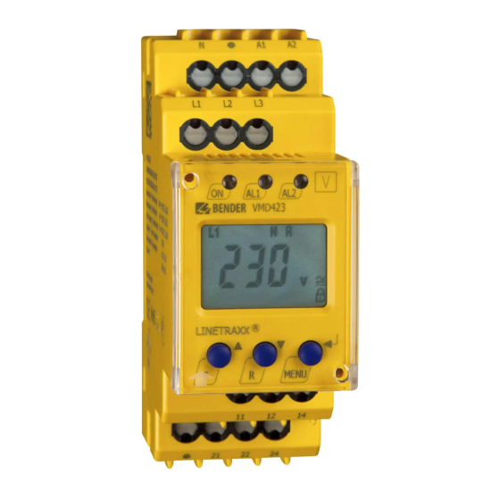
- Page 1 Operating Manual Voltage and frequency monitor for monitoring of 3(N)AC systems up to 0...500 V for undervoltage and overvoltage and under and overfrequency Software version: D345 V3.1x Power in electrical safety TGH1445en/04.2011...
- Page 2 Dipl.-Ing. W. Bender GmbH & Co. KG Londorfer Str. 65 • 35305 Grünberg • Germany Postfach 1161 • 35301 Grünberg • Germany Tel.: +49 6401 807-0 Fax: +49 6401 807-259 E-Mail: info@bender-de.com Web: http://www.bender-de.com © Dipl.-Ing. W. Bender GmbH & Co. KG All rights reserved.
- Page 3 Table of Contents 1. How to use this documentation effectively ..........5 How to use this manual ................. 5 2. Safety ........................7 General ......................... 7 Intended use ...................... 7 Skilled person ....................7 Safety information on work activities on electrical installations .. 8 3.
- Page 4 Table of Contents Installing the device ..................16 4.1.1 DIN rail mounting: ..................16 4.1.2 Screw mounting .................... 16 Wiring of the device ..................17 Commissioning / factory setting ............. 19 5. Operation and setting .................. 21 Getting to know the user interface ............21 Understanding standard display indications ........
- Page 5 1. How to use this documentation effectively 1.1 How to use this manual This operating manual is designed for skilled persons working in electrical en- gineering and electronics and must always be kept in an easily accessible lo- cation near to the equipment. In order to make it easier for you to find specific text passages or references in this manual and for reasons of comprehensibility, important information is emphasised by symbols.
- Page 6 How to use this documentation effectively TGH1445en/04.2011...
- Page 7 "Important safety instructions for Bender products“. 2.2 Intended use The voltage monitor VMD423H is used in 3(N)AC systems in accordance with VDE V 0126-1-1 for undervoltage, overvoltage, underfrequency and overfre- quency monitoring. The device is suitable for the nominal voltage range U 70...500 V in the frequency range 40...65 Hz.
- Page 8 Safety 2.4 Safety information on work activities on electrical in- stallations Touching live parts will cause danger of electric shock with fatal consequences! All work activities on electrical installations as well as installation activities, commis- sioning activities and work activities with the device in operation may only be carried out by electrically skilled persons! Danger of electric shock!
- Page 9 3. Function 3.1 Device features The VMD423H is internally supplied by the nominal voltage U Monitoring for undervoltage and overvoltage and underfrequency and overfrequency in 3(N)AC systems of AC 70...500 V / 70...288 V Monitoring of overvoltage U2 by average determination of the latest...
- Page 10 Function 3.2 Function Once the nominal voltage is applied, the start-up delay plus response delay (t ) begins. Throughout this time, an alarm is output via alarm LEDs and on1/2 relays. Measured voltage and frequency values being changed during this start-up period t do not influence the alarm LEDs and the state of the alarm re- lays.
- Page 11 3.2.4 Functional faults If an internal malfunction occurs, all three LEDs flash. An error code will appear on the display (E01...E32). In such a case please contact the Bender Service. 3.2.5 Fault memory The fault memory can be activated, deactivated or can be set to continuous mode (con).
- Page 12 By default, the password protection is activated (on). Settings are only possi- ble after entering the correct password (0...999). If you cannot operate your device because you cannot remember your password, please contact in- fo@bender-service.com. 3.2.12 Factory setting FAC After activating the factory setting, all settings previously changed are reset to delivery status.
- Page 13 Function K2 switches back to the initial position provided that no fault is detected at the measuring input. The following diagrams show the effect of a fault during a simulated alarm. Faults at the measuring input and the resulting condition of the alarm relay K1 (K2) are shown as a hatched area.
- Page 14 Function TGH1445en/04.2011...
- Page 15 4. Installation, connection and commissioning Danger of electric shock! Make sure that the installation area is disconnected from any electrical source before starting installation works and that the nominal voltage and supply voltage specified in the relevant data sheet are observed! TGH1445en/04.2011...
- Page 16 Installation, connection and commissioning 4.1 Installing the device Zubehör/ Accessory Fig. 4.1: Dimension diagram and drawing for screw fixing 4.1.1 DIN rail mounting: 1. Snap the rear mounting clip of the device into place in such a way that a safe and tight fit is ensured. 4.1.2 Screw mounting 1.
- Page 17 Installation, connection and commissioning 4.2 Wiring of the device Connect the device according the wiring diagram. Connect the conductor to the push-wire ter- minals according to the drawing. Terminal Connections Connection to the sys- L1, L2, L3, (N) tem to be monitored 11, 12, 14 Alarm relay K1 21, 22, 24 Alarm relay K2 Fig.
- Page 18 Example: Application of a photovoltaic system encountered in practice VMD423H Fig. 4.3: Application of an VMD423-D-2 in a photovoltaic system. Connect the terminals L1/L2/L3 of the VMD423H always to the supply side of the system to be monitored (but not to the inverter side of the disconnecting relay).
- Page 19 Installation, connection and commissioning 4.3 Commissioning / factory setting Material damage by improper connection of the device! Prior to commissioning make sure that the device is properly connected! Undervoltage < U: 184 V Overvoltage > U1: 264 V Overvoltage > U2 (10 min.): 253 V Hysteresis U: Underfrequency <...
- Page 20 Installation, connection and commissioning TGH1445en/04.2011...
- Page 21 5. Operation and setting 5.1 Getting to know the user interface Device front Element Function Power On LED, green Menu item LEd deactivated: AL1, LED Alarm 1 lights (yellow): Response value > U reached LED Alarm 2 lights (yellow): Response value < U reached Menu item LEd deactivated: AL1 AL2...
- Page 22 Operation and setting Device front Element Function Reset button (> 1.5 s): To delete the fault memory; Down key (< 1.5 s): Menu items/values MENU key (> 1.5 s): MENU, To start the menu mode; Enter key (< 1.5 s): To confirm menu item, submenu item and value.
- Page 23 Operation and setting 5.2 Understanding standard display indications Fig. 5.1: Standard displays Indication LINE CONDUCTORS L1-L3: Indication TYPE OF VOLTAGE: Shows the active line conductors. Shows the type of voltage. Indication ASYMMETRY: PASSWORD PROTECTION ENABLED: Shows the asymmetry value as %. Indicates that password protection is ac- Indication NEUTRAL CONDUCTOR: tivated.
- Page 24 Operation and setting 5.3 Getting to know keys and key functions The following table shows the functions of the keys for navigation on the dis- play, navigation through the menu and parameter setting. From "chapter 5.4 Querying values" onwards, only the respective key symbols are used for que- rying values.
- Page 25 Operation and setting 5.4 Querying values By default, the phase voltage between L1 and N is indicated. By pressing the UP and DOWN key, the phase voltage between L1 and L3, L2 and L3 as well as asymmetry, system frequency and phase sequence as well as the average val- ue of U2 can be queried.
- Page 26 Operation and setting Query Display indication 7. Query asymmetry 8. Change display indication 9. Query system frequency 10. Change display indication 11. Query phase sequence 12. Change display indication 13. Query average value of U2 TGH1445en/04.2011...
- Page 27 Operation and setting 5.5 Starting the self test manually The self test described on page 10 can also be started manually. During the self test, internal functional faults are detected and are indicated as error codes on the display. The alarm relays are not tested during this time. In order to start the self test manually: 1.
- Page 28 Operation and setting In this case, we assume, the response value for undervoltage is to be changed. During the sequence of operation, you need to confirm the password entry before carrying out the next step in the operation. TGH1445en/04.2011...
- Page 29 Operation and setting 5.8.2 Selecting menu items Press the ENTER key for more than 1.5 seconds to call up the menu. Menu items for different settings are available. Some menu items consist of several submenu items. The UP/DOWN keys can be used to navigate through the menu items.
- Page 30 Operation and setting Menu item/ENTER key Description/parameter setting 2. Press the UP/DOWN key to select the next menu item. Adjust delays: Response delay t Start-up delay t Delay on release t (LED, relay) 3. Press the UP/DOWN key to select the next menu item. Setting the parameters for device control Select method of measurement 3Ph or 3n Enable or disable password protection, change password...
- Page 31 Operation and setting 5.8.3 Carrying out settings in the menu item AL 1. Select menu item AL. 2. Carry out parameter change as illustrated below. 3. Keep the ENTER key pressed for more than 1.5 seconds to return to the menu item level after parameter change.
- Page 32 Operation and setting Menu item Activate/deactivate pa- Change display Change/save par- Select submenu item rameters parameter value 5. Set the response value undervoltage2 6. Select sub- menu item 7. Set the hystere- sis for voltage response values 8. Select sub- menu item 9.
- Page 33 Operation and setting Menu item Activate/deactivate pa- Change display Change/save par- Select submenu item rameters parameter value 12. Select sub- menu item 13. Set the response value for overfre- quency 14. Select sub- menu item 15. Set the hystere- sis for frequency response value 16.
- Page 34 Operation and setting Menu item Activate/deactivate pa- Change display Change/save par- Select submenu item rameters parameter value 19. Return to menu item AL TGH1445en/04.2011...
- Page 35 Operation and setting 5.8.4 Carrying out settings in the menu item out 1. Select menu item out. 2. Carry out parameter change as illustrated below. 3. Keep the ENTER key pressed for more than 1.5 seconds to return to the menu item level after parameter change.
- Page 36 Operation and setting Menu item Activate/deactivate/ Change display Change/save par- Select submenu item change param. parameter value 3. Select sub- menu item 4. Setting the alarm relay K1 to N/O opera- tion (n.o.) 5. Setting the alarm relay K1 to N/C opera- tion (n.c.) 6.
- Page 37 Operation and setting Menu item Activate/deactivate/ Change display Change/save par- Select submenu item change param. parameter value 8. Set alarm relay K2 to N/C oper- ation (n.c.) 9. Select sub- menu item 10. LEDs AL1/AL2 show the alarm status of K1/K2 11.
- Page 38 Operation and setting Menu item Activate/deactivate/ Change display Change/save par- Select submenu item change param. parameter value 14. Assign under- voltage fault to alarm relay K1 15. Change cate- gory 16. Assign overvolt- age fault1 to alarm relay K1 17. Change cate- gory 18.
- Page 39 Operation and setting Menu item Activate/deactivate/ Change display Change/save par- Select submenu item change param. parameter value 23. Change cate- gory 24. Assign phase sequence fault to alarm relay 25. Change cate- gory 26. Assign overvolt- age fault2 to alarm relay K1 27.
- Page 40 Operation and setting Menu item Activate/deactivate/ Change display Change/save par- Select submenu item change param. parameter value 32. Assign category Assignment is carried out in exactly the same way as for alarm device error to relay K1 alarm relay K2 33.
- Page 41 Operation and setting 5.8.5 Carrying out settings in the menu item t 1. Select menu item t 2. Carry out parameter change as illustrated below. 3. Keep the ENTER key pressed for more than 1.5 seconds to return to the menu item level after parameter change.
- Page 42 Operation and setting 5.8.6 Carrying out settings in the menu item SEt 1. Select menu item SEt. 2. Carry out parameter change as illustrated below. 3. Keep the ENTER key pressed for more than 1.5 seconds to return to the menu item level after parameter change.
- Page 43 Operation and setting Menu item Activate/deactivate/ Change display Change/save par- Select submenu item change param. parameter value 4. Disable pass- word protection 5. Enable pass- word protec- tion and enter password (3- digit numerical code) 6. Select sub- menu item TGH1445en/04.2011...
- Page 44 Operation and setting Menu item Activate/deactivate/ Change display Change/save par- Select submenu item change param. parameter value 7. Re-establish factory setting The text "run“ will appear on the display and the device will automatically reset to factory setting. 8. Select sub- menu item 9.
- Page 45 Operation and setting 5.8.8 Querying and clearing fault memory in the menu item HIS 1. Select menu item HIS. 2. Change parameters according to table. 3. Keep the ENTER key pressed for more than 1.5 seconds to return to the menu item level after parameter change.
- Page 46 Operation and setting Menu item HiS Fault indication /Submenu item 9. Query frequency fault (overfrequency) 10. Select fault indication 11. Indicate average value (L2 or L3 can also be indicated) 12. Select fault indication 13. To clear the fault memory 14.
- Page 47 6. Technical data 6.1 Data in tabular form ( )* = factory setting Insulation coordination acc. to IEC 60664-1 / IEC 60664-3 Rated insulation voltage ............................400 V Rated impulse voltage/pollution degree......................4 kV / III Protective separation (reinforced insulation) between ......(N, L1, L2, L3) - (11, 12, 14) - (21, 22, 24) Voltage test acc.
- Page 48 Technical data Relative uncertainty, voltage at 50 Hz/60 Hz................... ±1.5 %, ±2 digits Underfrequency< Hz ........................45...65 Hz (47.5 Hz)* Overfrequency > Hz ........................45...65 Hz (50.2 Hz)* Resolution of setting f ............................0.1 Hz Hysteresis frequency Hys Hz ......................0.1...2 Hz (0.1 Hz)* Relative uncertainty frequency in the range of 40...65 Hz ..............
- Page 49 Technical data ................underfrequency < Hz, overfrequency > Hz, phase sequence PHS , ................overvoltage > U2, alarm when starting S.AL, N/C operation n.c.)* Electrical endurance......................10000 switching operations Contact data acc. to IEC 60947-5-1: Utilisation category ............. AC 13 ..AC 14 ..DC-12..DC-12 ..DC-12 Rated operational voltage ..........
- Page 50 Technical data Test opening, diameter............................2.1 mm General data Operating mode ........................... continuous operation Mounting ..............................any position Degree of protection, internal components (IEC 60529)..................IP30 Degree of protection, terminals (IEC 60529) ......................IP20 Enclosure material ............................ polycarbonate Flammability class ............................UL94 V-0 DIN rail mounting acc.
- Page 51 Technical data 6.3 Ordering information Nominal voltage U Device type Art. No. VMD423H-D-3 3(N)AC 70...500 V/ 288 V (push-wire B 7301 0022 40...65 Hz terminals) 3(N)AC 70...500 V/ 288 V VMD423H-D-3 B 9301 0022 40...65 Hz *Absolute values of the voltage range...
- Page 52 Technical data TGH1445en/04.2011...
- Page 53 INDEX Alarm LEDs show which relay is in the alarm Getting 21 state 12 Automatic self test 10 How to use this manual 5 currently measured values Indication of the alarm state of K1/K2 12 - asymmetry 25 Installation and connection 15 - phase sequence 25 - Phase voltage 25 - Query average value of U2 26...
- Page 54 Menu, leave 27 To clear the fault memory 27 Menu, settings 27 Mounting clip for screw fixing 51 User interface 21 Operating elements, function 21 Wiring diagram 17 Operation and setting 21 Work activities on electrical installations 8 Ordering information 51 Password protection 12 Preset function 10 Querying values 25...
- Page 56 Dipl.-Ing. W. Bender GmbH & Co. KG Londorfer Str. 65 • 35305 Grünberg • Germany Postfach 1161 • 35301 Grünberg • Germany Tel.: +49 6401 807-0 Fax: +49 6401 807-259 E-Mail: info@bender-de.com Web: http://www.bender-de.com...
Need help?
Do you have a question about the VMD423H and is the answer not in the manual?
Questions and answers