Graco SaniForce 24V310 Instructions - Parts Manual
Piston pump elevator packages
Hide thumbs
Also See for SaniForce 24V310:
- Instructions - parts manual (38 pages) ,
- Instructions - parts manual (38 pages)
Table of Contents
Advertisement
Quick Links
Instructions/Parts
SaniForce® Piston
SaniForce®
SaniForce®
Elevator
Elevator Packages
Elevator
Packages
Packages
For use
use in in in sanitary
sanitary applications
applications to to to transfer
For
For
use
sanitary
applications
approved
approved for
approved
for use
for
use in in in European
use
European explosive
European
Important
Important Safety
Important
Safety
Safety Instructions
Read all warnings and instructions in this manual. Save
instructions.
instructions.
instructions.
Maximum Air Inlet Pressure: 100 psi
(0.7 MPa, 7.0 bar)
NOTE: If using an electric progressive
cavity pump, refer to the pump
manual for all functions for operation
and maintenance of the pump. For
operation and mantenance of the
elevator, refer to this manual.
Piston Pump
Pump
Piston
Pump
transfer low
low to to to medium
transfer
low
explosive atmosphere
explosive
atmosphere locations.
atmosphere
Instructions
Instructions
PROVEN QUALITY. LEADING TECHNOLOGY.
medium viscosity
viscosity fluids.
fluids. For
medium
viscosity
fluids.
locations.
locations.
Save these
Save
these
these
333406D
For professional
professional use
use only.
only. Not
For
professional
use
only.
EN
Not
Not
Advertisement
Table of Contents

Related Manuals for Graco SaniForce 24V310


Summary of Contents for Graco SaniForce 24V310
- Page 1 Instructions/Parts SaniForce® Piston Piston Pump Pump SaniForce® SaniForce® Piston Pump 333406D Elevator Elevator Elevator Packages Packages Packages For use use in in in sanitary sanitary applications applications to to to transfer transfer low low to to to medium medium viscosity viscosity fluids.
-
Page 2: Table Of Contents
Contents Contents Contents Models............... 3 Change Drums ..........16 Clean the Elevator and Pump ....... 17 Warnings ............5 Shutdown ............ 17 System Components........... 8 Troubleshooting..........18 Installation............9 Repair..............19 Choose a Location ........9 Replace Elevator Seal ........19 Unpack the Equipment ......... -
Page 3: Models
Models Models Models Models See ID tag on side of air motor (located under the motor cover) for model number. Includes: Includes: Includes: Model Model Model Cart Cart Cart and and Handle Handle Handle Pump Pump Pump Packings Packings Packings Pump Pump Brackets Pump... - Page 4 SaniForce 1590, 3150 HS 3-A Certified Air-Operated Double Diaphragm Pumps SaniForce 2:1, 5:1, 6:1, and 12:1 Air-Operated Piston Pumps SaniForce Diaphragm Pump and Piston Pump Drum Unloaders SaniForce Piston Pump Elevators SaniForce Diaphragm Pump and Piston Pump Bin Evacuation Systems Bradley A. Byron Quality Manager Graco Inc. 333406D...
-
Page 5: Warnings
Warnings Warnings Warnings Warnings The following warnings are for the setup, use, grounding, maintenance and repair of this equipment. The exclamation point symbol alerts you to a general warning and the hazard symbol refers to procedure-specific risks. When these symbols appear in the body of this manual or on labels refer back to these Warnings. Product-specific hazard symbols and warnings not covered in this section may appear throughout the body of this manual where applicable. - Page 6 Warnings WARNING WARNING WARNING EQUIPMENT EQUIPMENT EQUIPMENT MISUSE MISUSE HAZARD MISUSE HAZARD HAZARD Misuse can cause death or serious injury. • Do not operate the unit when fatigued or under the influence of drugs or alcohol. • Do not exceed the maximum working pressure or temperature rating of the lowest rated system component.
- Page 7 Warnings WARNING WARNING WARNING TOXIC TOXIC TOXIC FLUID FLUID OR FLUID OR FUMES FUMES HAZARD FUMES HAZARD HAZARD Toxic fluids or fumes can cause serious injury or death if splashed in the eyes or on skin, inhaled, or swallowed. • Read MSDSs to know the specific hazards of the fluids you are using. •...
-
Page 8: System Components
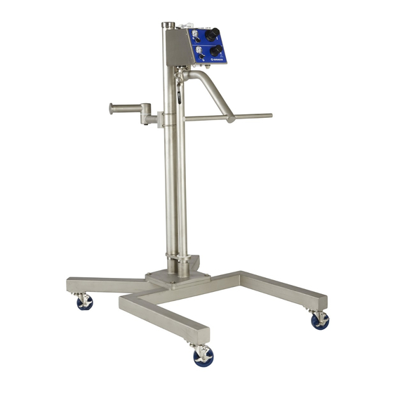
System Components System Components Components System System Components All models include the elevator (1), the articulating include the handle (4) and the cart (5). Some models arm (2), and a mounting kit (3). Mobile models also also include a pump (6). 1 Elevator Frame —... -
Page 9: Installation
3. Check the contents for loose or damaged parts. 4XØ 0.5" 4. Compare the packing slip against items inside the boxes. Immediately call your Graco distributor about any shortages or damage. 5. Remove the components from the boxes. Mobile Mobile... - Page 10 Installation 2. Attach the articulating arm. All models: models: Remove 4 nuts (308), washers (307) models: and the u-bolt (306) from the arm. Place the arm on the elevator riser tube at the desired mounting level for your pump. Reattach the u-bolt and hand-tighten the nuts to secure the arm to the tube.
-
Page 11: Ground The Equipment
Grounding provides an escape wire for the electrical current. Pump: Pump: Pump: Connect a ground wire (Graco PN 238909) to the ground screw on the air motor base. Connect the other end of the ground wire to a true earth ground. Air and... -
Page 12: Setup
Figure 6 is only a guide for selecting and installing system components and accessories. Contact your Graco distributor for assistance in designing a system to suit your particular needs. 1. Connect the master air supply to the 1/2 npt(f) main air inlet valve (B). - Page 13 Installation Figure 6 Typical Installation, mobile model shown System Components Components (included) (included) System Accessories Accessories System System Components (included) System System Accessories (sold (sold separately) (sold separately) separately) Pump; 5:1 model shown Main air line, 100 psi (0.7 MPA, 7.0 bar) maximum, regulated and filtered air Main air inlet valve Pump ground wire (required)
-
Page 14: Operation
Operation Operation Operation Operation 5. Close the main air valve. Flush Before Before First First Use Flush Flush Before First Moving parts can pinch or crush your fingers or hands. When raising or lowering the elevator, keep fingers and hands away from the elevator, The sanitary pump was assembled using sanitary articulating arm, drum cover, and the lip of the lubricant on moving parts and was tested in water. -
Page 15: Start And Adjust The Elevator
Operation Start and and Adjust Adjust the the Elevator Elevator Start Start Adjust Elevator 5. With your hands away from the drum, set the elevator director switch to DOWN. Mobile Fully lower the pump into the drum. Mobile Mobile models: models: models: Lock the cart wheels. -
Page 16: Start And Adjust The Pump
Operation Start and and Adjust Adjust the the Pump Pump Start Start Adjust Pump 2. Turn the pump air switch to OFF when the drum is empty, or any time the pump begins to run too fast. 1. Set the pump air switch to ON. Slowly increase pump air regulator pressure until NOTICE... -
Page 17: Clean The Elevator And Pump
Operation Clean the the Elevator Elevator and and Pump Pump Clean Clean Elevator Pump 3. Remove the pump. a. Disconnect the fluid hose. b. Use the elevator to remove the pump from the drum. c. Stationary Stationary models: Stationary models: Remove the drum. models: NOTE: The following instructions are a basic NOTE:... -
Page 18: Troubleshooting
Troubleshooting Troubleshooting Troubleshooting Troubleshooting 1. Follow Pressure Relief Procedure, page 2. Check all possible remedies in the Troubleshooting Chart and in your pump manual Troubleshooting Chart before disassembling the elevator riser or the pump. Problem Problem Problem Cause Cause Cause Solution Solution Solution... -
Page 19: Repair
Repair Repair Repair Repair Replace Replace Replace Elevator Elevator Seal Elevator Seal Seal 3. Apply appropriate waterproof sanitary lubricant to the inside surface of the tube. Reassemble in reverse order. 1. Remove the cap (122). 4. Apply medium-strength thread sealant to the 2. -
Page 20: Service The Pump
Repair Service the the Pump Pump Remove Water Water from from Air Air Cylinder Cylinder Service Service Pump Remove Remove Water from Cylinder Occasionally water may accumulate in the cylinder from condensation. 1. Follow the Pressure Relief Procedure, page 2. Remove the plug (134). 1. - Page 21 Notes Notes Notes Notes 333406D...
-
Page 22: Parts
Parts Parts Parts Parts Parts Parts Parts 333406D... - Page 23 Parts Part Description Description Description Part Part 24V299 ELEVATOR, sanitary, see page 24 ARM, articulating, see page 28 24V301 for mobile models 24V302 for stationary models KIT, mounting, pump, see pages 28–30 24V303 for 2:1 or electric progressive cavity pump 24V304 for 5:1 pump 24V307...
- Page 24 Parts Sanitary Elevator Elevator Kit Kit 24V299 24V299 Sanitary Sanitary Elevator 24V299 333406D...
- Page 25 Parts Elevator Kit Kit 24V299 24V299 Elevator Elevator 24V299 Description Description Part Part Part Description Description Part Part Part Description Description 24V123 24V123 24V123 BASE, elevator, sanitary 17A172 17A172 CAP, cylinder 17A172 107306 O-RING, FKM 16Y935 CAP, post 16Y935 16Y935 16Y925 POST, elevator 111178 O-RING, FKM 16Y925...
- Page 26 Parts Air Controls, Controls, Kit Kit 24V172 24V172 Controls, 24V172 333406D...
- Page 27 Parts Air Control Control 24V172 24V172 Control 24V172 Description Description Part Part Part Description Description Part Part Part Description Description 054760 TUBE, polyurethane, 4.25 500171 SCREW, socket head cap round, black 17A237 NUT, 5/16 nyloc, SST 100451 COUPLING 109478 NUT, lock, hex, SST 100896 BUSHING, pipe 115814 WASHER, flat, SST 114111 CONNECTOR, male...
- Page 28 Parts Articulating Arm Arm 24V301 24V301 (Refs (Refs 301–309) 301–309) and and 24V302 24V302 (Refs (Refs 301, 301, 303–309) 303–309) Articulating Articulating 24V301 (Refs 301–309) 24V302 (Refs 301, 303–309) Part Part Part Description Description Description 24V130 ARM, inside 24V130 24V130 16E096 16E096 PIN, dowel, for model 16E096...
- Page 29 Parts Mounting Kit Kit 24V304, 24V304, for for 5:1 5:1 Pumps Pumps Mounting Mounting 24V304, Pumps Part Part Part Description Description Description 17A121 BRACKET, mounting 17A121 17A121 17A120 17A120 17A120 CLAMP, tie rod 127586 127586 127586 SCREW, socket head, 3/8–16 x 1.25 112914 WASHER, plain 102471 SCREW, cap, hex, 3/8–16 127624...
- Page 30 Parts Mounting Kit Kit 24V307, 24V307, for for 6:1 6:1 Pumps Pumps Mounting Mounting 24V307, Pumps Description Part Part Part Description Description 17A123 17A123 17A123 BRACKET, mounting 17A120 17A120 17A120 CLAMP, tie rod 127586 SCREW, socket head, 127586 127586 3/8–16 x 1.25 112914 WASHER, plain 102471 SCREW, cap, hex, 3/8–16 127624 SCREW, pan, phillip’s...
- Page 31 Parts Drive Handle Handle Kit Kit 24V306 24V306 Drive Drive Handle 24V306 Part Description Description Description Part Part 24V148 BAR, handle 24V148 24V148 113976 SCREW, cap, hex, 3/8–16 x 1/5 112914 WASHER, plain 102021 NUT, hex 3/8 333406D...
- Page 32 Parts Cart Kit Kit 24V305 24V305 Cart Cart 24V305 Description Part Part Part Description Description – — FRAME, cart, 304 stainless steel 17A126 17A126 17A126 CASTER, swivel 105473 WASHER, plain 112904 WASHER, lock 108946 NUT, hex head, SST 556538 WASHER, lock, SST, 1/2 556538 556538 127602...
-
Page 33: Dimensions
Dimensions Dimensions Dimensions Dimensions 333406D... - Page 34 Dimensions Mobile Models Models Stationary Models Models Mobile Mobile Models Stationary Stationary Models Reference Reference Reference A — Raised 254.0 A — Lowered 57.25 145.4 40.375 102.6 41.25 104.8 30.5 333406D...
-
Page 35: Appendix A: Air Connections
Appendix A: Air Connections Appendix A: A: A: Air Appendix Appendix Connections Connections Connections The air controls are shipped completely assembled. Should a connection loosen, or a part need to be replaced, this page shows air connection points. The next page shows tube lengths and the correct connection for each end of the tube. - Page 36 Appendix A: Air Connections V1-A1 V2-A V1-A2 4X 5.5 in. (13.97 cm) R1-A R2-A R2-B V3-RP V4(B) V4(A) R2 R1 R1-B 10.0 in. (25.4 cm) 8.5 in. 10.0 in. (21.59 cm) (25.4 cm) 9.0 in. (22.86 cm) 7.0 in. 8.0 in. 4.38 in.
-
Page 37: Technical Data
Technical Data Technical Data Data Technical Technical Data SaniForce Piston Piston Pump Pump Elevator Elevator SaniForce SaniForce Piston Pump Elevator U.S. U.S. U.S. Metric Metric Metric Maximum Air Inlet Pressure 100 psi 7.0 bar, 0.7 MPa Maximum Fluid Working Pressure 2:1 Pumps 250 psi 17 bar, 1.7 MPa... - Page 38 Graco to be defective. This warranty applies only when the equipment is installed, operated and maintained in accordance with Graco’s written recommendations. This warranty does not cover, and Graco shall not be liable for general wear and tear, or any malfunction, damage or wear caused by faulty installation, misapplication, abrasion, corrosion, inadequate or improper maintenance, negligence, accident, tampering, or substitution of non-Graco component parts.
Need help?
Do you have a question about the SaniForce 24V310 and is the answer not in the manual?
Questions and answers