Graco Viscount II Instructions-Parts List Manual
4-ball pumps
Hide thumbs
Also See for Viscount II:
- Instructions-parts list manual (30 pages) ,
- Instructions-parts list manual (12 pages) ,
- Instructions manual (12 pages)
Table of Contents
Advertisement
Quick Links
Instructions - Parts List
Viscount
Hydraulic-powered pumps for low pressure, high volume circulation of finishing materials.
Do not use for flushing or purging lines with caustics, acids, abrasive line strippers, and
other similar fluids. For professional use only.
Important Safety Instructions
Read all warnings and instructions in
this manual. Save these instructions.
See page 3 for model information, including
maximum working pressure and approvals.
®
4-Ball Pumps
Viscount II
Pump with
4000cc 4-Ball
Lower
TI15609a
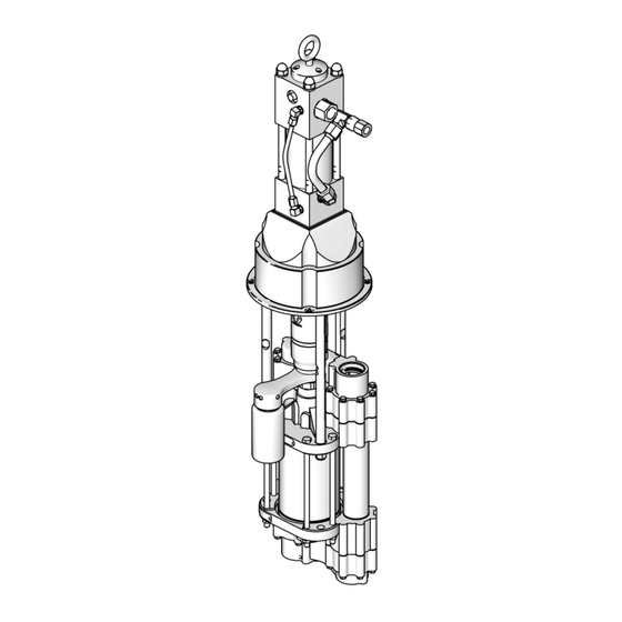
Viscount II
Pump with
2000cc 4-Ball
Lower
3A0537G
TI15600a
Viscount I Plus
Pump with
1000cc 4-Ball
Lower
II 2 G
EN
TI15601a
c IIB T3
Advertisement
Table of Contents

Related Manuals for Graco Viscount II


Summary of Contents for Graco Viscount II
- Page 1 For professional use only. Important Safety Instructions Read all warnings and instructions in this manual. Save these instructions. See page 3 for model information, including maximum working pressure and approvals. TI15609a Viscount II Pump with 4000cc 4-Ball Lower TI15600a Viscount II Pump with...
-
Page 2: Table Of Contents
Hydraulic Power Supply Check ... . . 12 Graco Information ......30 Stall Test . -
Page 3: Models
2000cc Viscount I Plus Chromex Chrome 24E492 167 (1.2, 12.0) 2000cc Viscount I Plus Chromex MaxLife 24E334 460 (3.2, 32.0) 2000cc Viscount II Chromex Chrome 24E335 460 (3.2, 32.0) 2000cc Viscount II tri-clamp Chromex Chrome 24E336 460 (3.2, 32.0) 2000cc... -
Page 4: Warnings
Warnings Warnings The following warnings are for the setup, use, grounding, maintenance, and repair of this equipment. The exclama- tion point symbol alerts you to a general warning and the hazard symbols refer to procedure-specific risks. When these symbols appear in the body of this manual, refer back to these Warnings. Product-specific hazard symbols and warnings not covered in this section may appear throughout the body of this manual where applicable. - Page 5 Warnings WARNING WARNING WARNING WARNING EQUIPAMENTO DE PROTECÇÃO PESSOAL Utilize equipamento de proteção adequado ao usar o equipamento ou se estiver na área de funcionamento do mesmo. O equipamento protege-o de lesões graves, tais como lesões oculares, perda de audição, inalação de vapores tóxicos e queimaduras.
-
Page 6: Installation
Installation Installation Grounding Air and fluid hoses: use only electrically conductive hoses with a maximum of 500 ft. (150 m) combined hose length to ensure grounding continuity. Check the electrical resistance of hoses. If total resistance to ground exceeds 25 megohms, replace hose immedi- ately. -
Page 7: Stand Mount
Installation Stand Mount Plumbing Mount the pump in the accessory pump stand (B). Use Install a fluid shutoff valve (D) between the mix tank (A) Part No. 253692 Stand for 750, 1000, 1500, and 2000cc and the pump. Pumps (see F . -
Page 8: Accessories
Installation Accessories • For Viscount II motors, use a minimum 22 mm (7/8 in.) ID return line (K). The motor has a 1 in. npt(f) hydraulic oil return fitting. Install the following accessories in the order shown in . 2, using adapters as necessary. - Page 9 Installation N P S TI15855a . 2. Typical Installation for 750, 1000, 1500, and 2000cc Pumps (Viscount I Plus Motor Shown) Key: Mix Tank Hydraulic Pressure Gauge 253692 Pump Stand Return Line Shutoff Valve Fluid Supply Line; 1-1/2 in. (38 mm) minimum diameter Supply Line Shutoff Valve Fluid Shutoff Valve Flow Control Valve...
- Page 10 Installation TI15856a . 3. Typical Installation for 3000 and 4000cc Pumps (Viscount II Motor Shown) Key: Mix Tank Drain Line 218742 Pump Stand Pressure Reducing Valve Fluid Supply Line; 1-1/2 in. (38 mm) minimum diameter Hydraulic Pressure Gauge Fluid Shutoff Valve Return Line Shutoff Valve Fluid Line;...
-
Page 11: Operation
Operation Operation Pressure Relief Procedure 7. Verify that pump actuations are priming the pump wet-cup. If not, confirm that the TSL pump piston is being depressed at bottom changeover, and that reservoir check valves are not stuck closed. 8. Close the fluid shutoff valve (D) downstream of the 1. -
Page 12: Maintenance
Maintenance Maintenance Preventive Maintenance Stall Test Schedule Perform a stall test periodically to ensure the piston seal is in good working condition and prevent system over- The operating conditions of your particular system pressurization: determine how often maintenance is required. Establish a preventive maintenance schedule by recording when Close the fluid shutoff valve (D) closest to the pump on and what kind of maintenance is needed, and then... -
Page 13: Changing The Tsl
Maintenance Changing the TSL To change the TSL: 1. Shut off the pump. Check the condition of the TSL and the level in the res- ervoir every week, minimum. TSL should be changed at least every month. Part No. 206995 Throat Seal Liquid (TSL) carries resi- due from the pump rod into the reservoir. -
Page 14: Troubleshooting
Troubleshooting Troubleshooting Problem Cause Solution Pump output low on both strokes. Restricted hydraulic supply lines. Clear any obstructions; be sure all shutoff valves are open; increase pressure, but do not exceed maximum working pres- sure. Exhausted fluid supply. Refill and reprime pump. Clogged fluid outlet line, valves, etc. -
Page 15: Repair
Repair Repair Disassembly Reassembly NOTE: The 3000 and 4000cc pumps are easiest to NOTE: If the coupling adapter (108) and tie rods (103) repair when left in the Part No. 218742 accessory pump have been disassembled from the motor, see Reas- stand and disassembled as instructed in the lower man- semble the Coupling Adapter and Tie Rods to the ual. - Page 16 Repair Viscount I Plus Viscount II Pump Viscount II Pump Pump with with 2000cc 4-Ball with 4000cc 4-Ball 1000cc 4-Ball Lower Lower Lower Part of 101 TI15602a TI15610a Torque to 90-100 ft-lb (122-135 N•m). TI15599a Torque to 50-55 ft-lb (68-75 N•m).
-
Page 17: Reassemble The Coupling Adapter And Tie Rods To The Motor
15-17 ft-lb (20-23 N•m). NOTE: 3000 and 4000cc Pumps do not have a coupling b. Viscount II motors: Torque the screws (109) to adapter (108) or a mounting plate (111). 50-55 ft-lb (68-75 N•m). 1. 750, 1000, 1500, and 2000cc Pumps only: Loosen, 7. -
Page 18: Parts
Parts Parts Viscount I Plus Pumps with 750cc, 1000cc, 1500cc, or 2000cc 4-Ball Lowers Common Parts Ref. No. Description Part No. 101 MOTOR, Viscount I Plus, see manual 261466 308330 102 LOWER, 4-Ball, see manual 3A0539 see tables 103 TIE ROD, 14.25 in. (362 mm) between 15G924 shoulders 104 NUT, lock, hex;... -
Page 19: Viscount Ii Pumps With 2000Cc 4-Ball Lower
Parts Viscount II Pumps with 2000cc 4-Ball Lower Common Parts Ref. No. Description Part No. 101 MOTOR, Viscount II, see manual 223646 308048 102 LOWER, 4-Ball, see manual 3A0539 see table 103 TIE ROD, 14.25 in. (362 mm) between 15G924 shoulders 104 NUT, lock, hex;... -
Page 20: Viscount Ii Pumps With 3000Cc Or 4000 Cc 4-Ball Lowers
Parts Viscount II Pumps with 3000cc or 4000 cc 4-Ball Lowers Common Parts Ref. No. Description Part No. 101 MOTOR, Viscount II, see manual 223646 308048 102 LOWER, 4-Ball, see manual 3A0540 see table 103 TIE ROD, 12.72 in. (323 mm) between... -
Page 21: Dimensions
Dimensions Dimensions Viscount I Plus Viscount II Pump with Pump with Viscount II Pump with 4000cc 4-Ball Lower 1000cc 4-Ball 2000cc 4-Ball Lower Lower TI15600a TI15601a TI15609a Approx. Weight Motor Lower Size in. (mm) in. (mm) in. (mm) lb (kg) 750cc 74 (33.6) -
Page 22: Motor Mounting Hole Diagrams
Motor Mounting Hole Diagrams Motor Mounting Hole Diagrams Viscount I Plus Adapter Plate 16E086 Viscount II Motor Mounting Hole Layout 4X 3/8-16 UNC - 2B 7.43 in. 4.508 in. Four 0.45 (11.4 mm) Four 0.344 (8.7 mm) (188 mm) diameter holes... -
Page 23: 255143 Wall Mount Bracket
255143 Wall Mount Bracket 255143 Wall Mount Bracket 17.8 in. (450.9 mm) 14.5 in. (368.3 mm) 2.0 in. (50.8 mm) 5.4 in. (136.5 mm) 7.4 in. (187.3 mm) 5.3 in. (133.4 mm) 1.0 in. (25.4 mm) 9.0 in. (228.6 mm) 1.6 in. -
Page 24: Technical Data
Technical Data Technical Data 750, 1000, 1500, and 2000cc Pumps with Viscount I Plus Motor Maximum Maximum Hydraulic Maximum Fluid Flow at Maximum Working Working Hydraulic 60 cycles Output Fluid Lower Pressure Pressure Hydraulic Oil Motor Fluid per minute per Cycle Temperature Model Size... -
Page 25: 2000Cc Pumps With Viscount Ii Motor
2000 150°F (66°C) Chart 24E493 2000cc 24E494 2000cc Sound data: See Viscount II manual 308048. Wetted parts: See 4-Ball Lower manual 3A0539. 3000 and 4000cc Pumps with Viscount II Motor Maximum Maximum Hydraulic Maximum Fluid Flow at Maximum Working Working... -
Page 26: Performance Charts
Performance Charts Performance Charts To find Fluid Outlet Pressure (psi/MPa/bar) at a spe- To find Motor Hydraulic Oil Consumption (l/min. or cific fluid flow (lpm/gpm) and operating hydraulic pres- gpm) at a specific fluid flow (l/min. or gpm): sure (psi/MPa/bar): 1. - Page 27 Performance Charts See Models on page 3 for your pump part number. Viscount I Plus Motor, 1500cc Lower Key: 10.3 MPa, 103 bar (1500 psi) hydraulic pressure 7.2 MPa, 72.4 bar (1050 psi) hydraulic pressure 4.1 MPa, 41 bar (600 psi) hydraulic pressure PUMP DELIVERY (Test Fluid: No.
- Page 28 Performance Charts See Models on page 3 for your pump part number. Viscount II Motor, 2000cc Lower CYCLES PER MIN. (l/min) 450 (3.1, 31) 8.0 (30.4) Key: 400 (2.8, 28) 10.3 MPa, 103 bar (1500 psi) 7.0 (26.6) hydraulic pressure 350 (2.4, 24)
- Page 29 4.1 MPa, 41 bar (600 psi) hydraulic pressure NOTE: The shaded area within the table shows the recommended range for continuous duty circulation applications. Viscount II Motor, 3000cc Lower Fluid Outlet Pressure Hydraulic Oil Consumption cycles per minute cycles per minute...
-
Page 30: Graco Standard Warranty
With the exception of any special, extended, or limited warranty published by Graco, Graco will, for a period of twelve months from the date of sale, repair or replace any part of the equipment determined by Graco to be defective.
Need help?
Do you have a question about the Viscount II and is the answer not in the manual?
Questions and answers