Table of Contents
Advertisement
Quick Links
Repair - Parts
Stainless Steel 3:1 Pump
For use in vapor abrasive blast equipment.
Use only with water, or water with additives to inhibit corrosion or mold.
For professional use only.
Important Safety Instructions
Read all warnings and instructions in this manual.
Save these instructions.
Model 24V672, 25A531, 17M893
300 psi (2.06 MPa, 20.6 bar) Maximum Fluid Working Pressure
100 psi (0.68 MPa, 6.8 bar) Maximum Air Working Pressure
333397B
EN
Advertisement
Table of Contents

Related Manuals for Graco 25A531


Summary of Contents for Graco 25A531
- Page 1 For professional use only. Important Safety Instructions Read all warnings and instructions in this manual. Save these instructions. Model 24V672, 25A531, 17M893 300 psi (2.06 MPa, 20.6 bar) Maximum Fluid Working Pressure 100 psi (0.68 MPa, 6.8 bar) Maximum Air Working Pressure...
-
Page 2: Table Of Contents
Reconnect the Displacement Pump ..10 Graco Standard Warranty ....28 Disassemble the Displacement Pump ..10 Reassemble the Displacement Pump . -
Page 3: Warnings
Warnings Warnings The following warnings are for the setup, use, grounding, maintenance, and repair of this equipment. The exclama- tion point symbol alerts you to a general warning and the hazard symbols refer to procedure-specific risks. When these symbols appear in the body of this manual or on warning labels, refer back to these Warnings. Product-specific hazard symbols and warnings not covered in this section may appear throughout the body of this manual where applicable. -
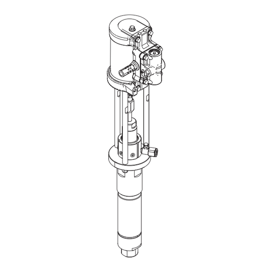
Page 4: Component Identification
Component Identification Component Identification . 1. Component Identification Ref. Description Ref. Description Displacement Rod Ground Screw Tie Rod Enclosed Wet Cup Coupling Nut Wet Cup Fill Port Tie Rod Nut Fluid Outlet Air Motor Fluid Inlet Sight Glass Lower Cylinder Outlet Housing 333397B... -
Page 5: General Information
This pump is intended to be mounted using a bracket to the frame of the system, which must be connected to earth ground. Before starting, fill wet cup fill port (C) 1/2 full with Graco Throat Seal Liquid (TSL) or compatible solvent. See F . 2. -
Page 6: Maintenance
Wet Cup Maintenance and what kind of maintenance is needed, and then determine a regular schedule for checking your system. Fill the Wet Cup half full with Graco TSL. Maintain level daily. 333397B... -
Page 7: Troubleshooting
Troubleshooting Troubleshooting NOTE: Perform Pressure Relief Procedure (page 5) before checking or servicing the equipment. NOTE: Check all possible problems and causes before disassembling the pump. Pump Problem Cause Solution Pump output is low on both strokes. Air supply lines are restricted. Clear any obstructions from the air lines. -
Page 8: Air Motor
Troubleshooting Air Motor Problem Cause Solution Air motor will not run. Damaged air valve (214). Replace or service the air valve (214). See F . 12, page 20. Damaged pilot valve (213). Replace the pilot valves (213). See F . 12, page 20. Air is continuously exhausting Damaged u-cups (207). -
Page 9: Pump Repair
See F . 1, page 4. • Always use Genuine Graco Parts and Accessories, available from your Graco distributor. Accessories 5. Refer to page 10 for displacement pump service. To must be adequately sized and pressure rated for service the air motor, refer to page 13. -
Page 10: Reconnect The Displacement Pump
(110). Take note which set of holes it is in, then during repair. Torque the enclosed wet cup (B) to 60 remove the ball (102). ft-lb (81 N•m). Fill the wet cup fill port (C) with Graco TSL. 6. Place the flats of the piston mounting stud (128) in a vise, and unscrew the piston stud (114). -
Page 11: Reassemble The Displacement Pump
Pump Repair Reassemble the Displacement 4. Screw the piston stud (114) onto the piston mount- ing stud (128). Torque to 50–70 ft-lb (68–95 N•m). Pump Install the piston ball (102) on the piston seat. Slide the ball stop pin (110) into the desired set of holes, 1. -
Page 12: Pump Diagram
Pump Repair Pump Diagram Torque to 60 ft-lb (4.1 N•m) Lips of v-packings must be face up Lubricate See Detail A Apply lubricant See Detail B Lips of v-packings must be face down Detail A: Throat Packings Detail B: Piston Packings ti23797a 333397B... -
Page 13: Air Motor Repair
Air Motor Repair Air Motor Repair 3. Attach the tie rod nuts (4) and torque to 15-20 ft-lb (20-27 N•m). 4. Hold the flats of the air motor piston rod with a wrench. Use another wrench to tighten the coupling Disconnect the Air Motor nut (9). - Page 14 Air Motor Repair Replace Seals or Rebuild Air Valve 2. See F . 6. Lubricate the u-cups (309) and install on the piston (306) with the lips facing toward the cen- Air Valve Seal Kits are available. See page 25 to order ter of the piston.
-
Page 15: Replace Pilot Valves
Air Motor Repair Replace Pilot Valves Repair Air Motor 1. Stop the pump at the middle of its stroke. Perform Disassemble the Air Motor the Pressure Relief Procedure, page 5. 2. Disconnect the air line to the motor. 1. For motors with DataTrak: Remove the screw to disconnect the reed switch from the air valve. - Page 16 Air Motor Repair Reassemble the Air Motor 8. See F . 9. Carefully place the bottom cover (201) on the cylinder (205). Slide the rod through the NOTE: For easier reassembly, start with the top cover bearing. The manifold surfaces of the top and bot- (210) turned over on the workbench and assemble the tom covers must align.
-
Page 17: Parts
24V671 LOWER, displacement, sst 17B185 ROD, tie (Pack of 3) 104541 NUT, lock 121022 FITTING, elbow, male, 1/4npt (model 24Y672 and 25A531 only) 127846 FITTING, elbow, male, 1/4npt (model 24V672 only) EQ1798 FITTING, PTC, male, 1/4npt (model 25A531 only) 114499... -
Page 18: Lower Parts
Parts Lower Parts . 11: Lower Parts 333397B... -
Page 19: Lower Parts List
Parts Lower Parts List Ref. Part Description Qty. Ref. Part Description Qty. 133‡ --- SPRING 101‡ 100063 PIN, cotter 134 --- SEAL, u-cup 102‡ 101917 BALL, bearing, .875 dia. 304 ss 135 117739 WIPER, rod 104‡ 164782 PACKING, o-ring, 2 1/16 x 2 1/4 136# 102228 COVER, oil hole 105‡... -
Page 20: Air Motor Parts
Parts Air Motor Parts Torque to 11-13 ft-lb (15-18 N•m) Apply lubricant. Torque to 95-105 in-lb . 12: Air Motor Parts 333397B... -
Page 21: Air Motor Parts List
Parts Air Motor Parts List Ref. Part Description Qty. 201 --- COVER, lower, 2.5 202* 108993 PACKING, o-ring 203 --- BEARING, 9/16 204* 117370 PACKING, o-ring 15M289 CYLINDER, motor, 2.5 15M302 COVER, bolt, 2.5 motor 207* --- SEAL, u-cup, .562 208* GASKET, cover, small 209*†... -
Page 22: Air Valve Parts
Parts Air Valve Parts 1. Apply grease to all o-rings, packings, and seals. . 13: Air Valve Parts Air Valve Parts List Ref. Part Description Qty. Ref. Part Description Qty. HOUSING, air valve, small, npt † O-RING, 018 buna 312... -
Page 23: Air Valve Parts List
Parts Air Valve Parts List Air valve parts are not sold individually. The table below shows possible kit options for each part. See page 25 to order the correct kit(s), or full replacement air valves, for your motor. Air Valve Air Valve Air Valve Ref. -
Page 24: Mounting Hole Diagram
Mounting Hole Diagram Mounting Hole Diagram M02LN0 (2.5 in.) 3 in. (76 mm) Two M8 mounting holes ti12734a Three 3/8-24 tie rod holes M8 X 1.25 3-1/4 in. (83 mm) bolt circle 2.2 in. (56 mm) ti12733a 2.5 in. (64 mm) 333397B... -
Page 25: Pump Kits And Accessories
Pump Kits and Accessories Pump Kits and Accessories Kit Description Kit Number Complete Air Valve Replacement Kit – Standard 24A351 * Air Motor Seal Kit 24A539 Air Valve Repair Kit 24A537 † Air Valve Seal Kit 24A535 Air Valve End Cap Kit – Standard 24A360 ‡... -
Page 26: Dimensions
Dimensions Dimensions Pump Air Motor 6.2 in. (157 mm) 6.8 in. 4.2 in. 5.1 in. (173 mm) (107 mm) (130 mm) 9.2 in. (234 mm) 333397B... -
Page 27: Technical Data
Technical Data Technical Data Stainless Steel 3:1 Pump - 24V672 Metric Maximum fluid working pressure 300 psi 2.06 MPa, 20.6 bar Maximum air inlet pressure 100 psi 0.68 MPa, 6.89 bar Minimum air inlet pressure 15 psi .0103 MPa, 1.03 bar Maximum ambient air temperature 49°... -
Page 28: Graco Standard Warranty
With the exception of any special, extended, or limited warranty published by Graco, Graco will, for a period of twelve months from the date of sale, repair or replace any part of the equipment determined by Graco to be defective.
Need help?
Do you have a question about the 25A531 and is the answer not in the manual?
Questions and answers