
Related Manuals for PKP DM08


Summary of Contents for PKP DM08
- Page 1 Instruction Manual DM08 Magnetic Inductive Flow Meter PKP Prozessmesstechnik GmbH Borsigstraße 24 D-65205 Wiesbaden-Nordenstadt Tel.: ++49-(0)6122-7055-0 Fax: ++49-(0)6122-7055-50 Email: info@pkp.de...
-
Page 2: Table Of Contents
10.1 Cleaning..........................51 10.2 Maintenance.........................51 10.3 Storage..........................52 11 Disassembly and disposal.......................52 12 Technical data.........................53 12.1 Characteristics of the DM08....................53 12.2 Materials..........................55 12.3 Dimensions and weights.......................56 12.3.1 Compact device.........................56 Please keep this operating manual for future reference. If the device is resold, please provide the operating manual along with it. - Page 3 Instruction Manual DM08 12.3.2 Separate version (with wall bracket).................57 - 2 - PKP Prozessmesstechnik • 09/2019...
-
Page 4: About This Operating Manual
Before each step, read through the relevant advice carefully and keep to the specified order. Thoroughly read and understand the information in the section "Safety instructions". If you have any problems or questions, please contact your supplier or contact us directly at: PKP Prozessmesstechnik GmbH Borsigstraße 24 D-65205 Wiesbaden-Nordenstadt... -
Page 5: Device Description
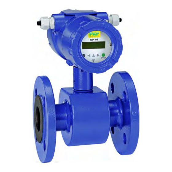
Instruction Manual DM08 Device description The DM08 flow meter from PKP is a flow sensor without moving parts. The measurement is per- formed using magnetic induction. The DM08 is used for measuring or dosing water and electrically conductive fluids. The complete measuring instrument comprises the sensor and the related display electronics. -
Page 6: Delivery, Unpacking And Accessories
Carefully unpack the unit to prevent any damage. Check the completeness of the delivery based on the delivery note. Scope of delivery: 1x DM08 according to the order data. 1x operating manual. certificates (optional) IMPORTANT! ... -
Page 7: Intended Use
Flow tube empty (partially filled). / Conductivity too low: Faulty measurements can occur if the flow tube of the DM08 is empty or partially filled or if the conductivity of the fluid being used is too low. -
Page 8: Safety Instructions
DM08"). Take appropriate measures to ensure that the medium does not freeze. Only use the DM08 if it is in perfect condition. Damaged or faulty devices must be checked without delay and, if necessary, replaced. When fitting, connecting and removing the DM08 use only suitable, appropriate tools. -
Page 9: Construction And Function
Construction and function Construction The DM08 comprises a sensor and the display electronics. The sensor is used to measure fluid media. The display electrodes generate the coil current required for the magnetic field and pre- pares the induced voltage applied to the electrodes. -
Page 10: Measuring Principle
The magnetic inductive flow sensor operates on the inductive principle, i.e., a direct current is gen- erated by the movement of a conductor in a magnetic field: The measuring pipe of the DM08 is in a magnetic field (B). An electrically conductive medium (Q) passes through the pipe. -
Page 11: Installation Instructions Display Electronics
For the separate version, the minimum permissible conductivity of the medium is determined by the distance between the sensor and the display electronics. The maximum cable length to ensure accuracy is 200 m (p. 19 "Connecting cables"). - 10 - PKP Prozessmesstechnik • 09/2019... -
Page 12: Instructions On Potential Equalisation And Cathode Protection
Instructions on potential equalisation and cathode protection 5.2.1 Potential equalisation The signal outputs (process outputs and the mains supply of the DM08 are galvanic isolated from each other. The housing and the interference filter of the mains supply are connected to PE. - Page 13 Create the potential equalisation in the separate design the same as described in the above sec- tions. For the potential equalisation, the display electronics and the sensor are connected to each other through Pin 7 of the connecting cable. - 12 - PKP Prozessmesstechnik • 09/2019...
-
Page 14: Cathodic Protectives
General: The DM08 can always be installed at any point on the pipeline in the horizontal as well as in vertical sections. Ideally, the sensor should be installed in a pipeline with a sufficient straight run, both before and after the measuring point. - Page 15 It must be ensured, that the axes of the electrodes are running horizontally to avoid erro- neous measurements due to deposits or air bubbles on the electrodes. Also, note that in case of deviations from horizontal, the functioning of the Empty pipe de- tection (p. 9) is limited. - 14 - PKP Prozessmesstechnik • 09/2019...
- Page 16 Instruction Manual DM08 Installation in unfilled pipeline: If a pipeline is not always filled, or in case of an open channel (drainage), the sensor must be installed in a siphon. That means the flow tube cannot run dry and is always filled with measured medium.
-
Page 17: Mounting
Instruction Manual DM08 Mounting As a compact device, the DM08 is installed directly into the pipeline. With the separate design, the sensor is installed in the pipeline. The display electronics can be attached to the wall with the bracket. IMPORTANT NOTICES: ... -
Page 18: Electrical Connection
The electrical connection of the DM08 should only be carried out by a fully qualified electrician. De-energize the electrical system before connecting the DM08. Make the electrical connection of the DM08 through the terminal strips in the interior of the display electronics. -
Page 19: Mains And Signal Cable
IMPORTANT! Pay attention to the clamping area of the cable gland! To guarantee the protection class as per DIN EN 60529, the connection cable being used must have a sheathing diameter that matches the cable gland. - 18 - PKP Prozessmesstechnik • 09/2019... - Page 20 Instruction Manual DM08 Terminal assignment: Terminal Label Function 115 / 230 V 24 V Protective con- ductor Neutral conductor Phase 24 V Pulse - Pulse output (passive) Pulse + Status - Status output (passive) Status + Current - Current output...
-
Page 21: Electrode And Magnetic Current Line
Only use cables as specified in chapter "Connecting cables“. The outer shield is grounded by means of special EMC-compliant cable glands at both ends of the cable. The inner shields are connected to terminal 7 and 22 respectively. - 20 - PKP Prozessmesstechnik • 09/2019... -
Page 22: Commissioning
Instruction Manual DM08 Commissioning Before switching on the DM08 for the first time, please observe the following instructions. Check that the DM08 has been installed correctly and that all screw connections are sealed. the electrical wiring has been connected properly. -
Page 23: Operation
Keys and their functions: There are six keys for operating and changing the settings. CAUTION! Material damage! Do not press these keys with sharp or sharp-edged objects such as pencils or screwdrivers! - 22 - PKP Prozessmesstechnik • 09/2019... - Page 24 Instruction Manual DM08 Cursor keys: These keys are used for change numerical values. give YES/NO answers. select parameters. Each key is assigned a symbol as follows: Cursor key, right arrow; Cursor key, left arrow; Cursor key, up arrow;...
- Page 25 Display mode is the standard (default) operating mode when the device is switched on. 2. Programming. The parameters of the DM08 can be changed in this operating mode. After entering the corres- ponding password, either only the customer-modifiable functions (customer password) or all func- tions (service password) are released for modification.
- Page 26 This password can be changed when the device is first put into operation. Therefore changes should be kept in a safe place. The factory setting for the DM08 customer password is: "0002". The service password allows modification of all functions and parameters. This password is not given to customers.
-
Page 27: Functional Classes (Main Menu)
Functional classes (main menu) The software functions of the DM08 are divided into functional classes. They are arrayed in a circle and can be navigated by using the ◄ or ► cursor keys. To go back to your starting point (the MEASURED VALUES functional class) press Esc. -
Page 28: Measured Values
Instruction Manual DM08 8.1.1 Measured values The MEASURED VALUES functional class in- Volume flow rate: cludes all functions for displaying the measured If you select the function the cur- volume flow values. rent value for the volume flow will be displayed. - Page 29 The only difference is, that in the first line the in the functional class SETTINGS meter value of the forward totalizer 2 is displayed. SENSOR + DM08“. XXX.X m3 Relative flow rate: XXX.XX m3/h The relative flow rate Q...
-
Page 30: Password
Instruction Manual DM08 QV + flow velocity: Raw value display: If the function QV+ flow velocity is selected, in The raw value display supports fault diagnostics the first line current value of the volume flow and trouble shooting. Please inform our service... - Page 31 A valid customer password allows changes for The customer password is intended to prevent all software parameters that are permissible for changes for software parameters of the DM08 customers. by the control unit without permission. After the operator switched off the device or no...
-
Page 32: Totalizer
When the unit is changed, the totalizers will be reset to 0.00 automatically! Totalizer reset: The display electronics of the DM08 has three independent totalizers. For changing the current settings and paramet- Totalizer 1 and Totalizer 2 for the forward flow ers the customer password is needed. -
Page 33: Measurement Processing
1 to 60s ("Input window / modify a value", p. 25). Notice After a jump in the measuring variable the output measured value reaches about 99% of the new set point after 5 The factory setting is 3 seconds. - 32 - PKP Prozessmesstechnik • 09/2019... -
Page 34: Flow
Instruction Manual DM08 8.1.5 Flow Low flow cut off: The FLOW functional class includes functions that affect lower- and upper-range values and is a threshold for flow low flow cut off the processing of the measured flow rates. rate (percentage the upper-range value). - Page 35 8.1.5.1 Scaling the outputs The measuring variable volume flow rate is shown by the DM08 as well as an analogue current output as a pulse output. The correlation of output and flow rate is not fixed but it can be defined by the parameters (see Fig).
- Page 36 Instruction Manual DM08 After choosing the function Volume flow upper- Volume flow limit MAX: range value and pressing the ENTER key, the The MAX limit value for volume flow can be following selection field will be displayed. shown by the status output.
-
Page 37: Pulse Output
When selecting "pulses", pulses per flow unit will be output by the transmitter. The pulse QV USL shape is defined by the parameters pulse out- +003580.0 m3/h put unit, pulse value and pulse width. Example: - 36 - PKP Prozessmesstechnik • 09/2019... - Page 38 Instruction Manual DM08 When choosing an improper combination of Pulse value: these parameters (e.g. the number of pulses This function is used to define how many pulses per time unit cannot be generated due to the will be output per accumulated unit.
-
Page 39: Status Output
For selecting the desired function please use the key ▲ or ▼. After selecting the function , press Status output state active state the ENTER key to display the current setting: Output active [closed] Example: - 38 - PKP Prozessmesstechnik • 09/2019... -
Page 40: Current Output
Instruction Manual DM08 8.1.8 Current output The CURRENT OUTPUT functional class in- The range from 4 to 20,5 mA is according to the cludes the settings for the current outputs of the NAMUR-recommendation and uses the meas- display electronics. uring range up 104%. -
Page 41: Simulation
For selecting the desired function within the class please use the keys ▲ and ▼ . Press ENTER key to display the current selec- tion for the type of simulation: Preset of [direct] Example: - 40 - PKP Prozessmesstechnik • 09/2019... - Page 42 Instruction Manual DM08 One of the following settings can be chosen Direct simulation – status output *: ("Selection window / make a selection", p. 25): Using the function Simulation direct the status output can be af- status output Setting Function fected directly.
-
Page 43: Self-Test
This function is useful for suppressing temperature dependencies of the display electronics. After selecting the function Self-test on/off using the key ▲ or ▼ press the ENTER key. The current setting will be displayed. - 42 - PKP Prozessmesstechnik • 09/2019... - Page 44 Instruction Manual DM08 Reference calibration on / off: Self-test The function Reference calibration [off] is used to enable or disable the period- on/off Example: ical recalibration of the transmitter. This function is useful for periodical self-monitoring and for maintaining the long-term stability of the display electronics.
-
Page 45: Settings Sensor
Example: For changing the parameter please refer to the description in Section "Input window / modify a value". Notice When entering 00 Min for this para- meter, the detection will be performed continuously. - 44 - PKP Prozessmesstechnik • 09/2019... - Page 46 A positive value is displayed again by changing Language: the sign of the CFH value. English and German are available for the user guidance of the DM08. No changes to the electrical cable connections are required. The function is intended for setting Language the language.
- Page 47 Mains frequency this parameter. The default setting is 50 Hz. After choosing the function Mains frequency using the key ▲ or ▼ and pressing Enter, the following selection field will be displayed reverse - 46 - PKP Prozessmesstechnik • 09/2019...
- Page 48 Software version (information field): Example: After selecting the function Software version the version of the DM08 software will be dis- played: After choosing the desired function using the Reset system error: key ▲ or ▼ and pressing Enter, the software...
-
Page 49: Errors And Returns
Comply with § Return shipment to the manufacturer "Return shipment to the manufacturer"! CAUTION! Material damage! The DM08 cannot be repaired by the user. In case of a defect, the device must be returned to the manufacturer for repair. -
Page 50: Self-Test Errors
Instruction Manual DM08 Self-test errors Self-test errors such as problems with a sensor line or inconsistent parameter settings are dis- played as textual error messages on the LCD. When the cause of error has been fixed, the mes- sage disappears from the display automatically. -
Page 51: Return Shipment To The Manufacturer
Due to legal requirements placed on environmental protection and occupational safety and health and to maintain the health and safety of our employees, all units returned to PKP for repair must be free of toxins and hazardous substances. That also applies to cavities in the devices. If neces- sary, the customer must neutralise or purge the unit before return to PKP. -
Page 52: Cleaning, Maintenance, Storage
DM08 10 Cleaning, maintenance, storage 10.1 Cleaning Clean the DM08 with a dry or slightly damp lint-free cloth. Do not use sharp objects or aggressive agents for cleaning. 10.2 Maintenance The DM08 is maintenance-free cannot be repaired by the user. In case of a defect, the device must be replaced or returned to the manufacturer for repair. -
Page 53: Storage
Compliant with the Directives 2011/65/EU (RoHS) and 2012/19/EU (WEEE)*, the device must be disposed of separately as electrical and electronic waste. No household waste! The DM08 consists of various different materials. It should not be disposed of with household waste. Comply with the relevant regulations of your country when disposing the units. -
Page 54: Technical Data
DM08 12 Technical data The technical data of customised versions may differ from the data in these instructions. Please observe the information specified on the type plate. 12.1 Characteristics of the DM08 Type DM08.15 … DM08.200 Characteristics Sensor Measuring range 0…10 m/s... - Page 55 Instruction Manual DM08 Type DM08.15 … DM08.200 Output signal display electronics Pulse / Frequency output: Signal type (selectable) Pulse signal or frequency signal Signal shape Square wave signal Pulse output Pulse rate: ] 1000 1000 1000 1000 1000 1000 1000 1000 100...
-
Page 56: Materials
Instruction Manual DM08 Type DM08.15 … DM08.200 Process variables Ambient temperature Hard rubber: 0...80 °C PTFE: -20…100 °C Display electronics: -20…50 °C (the readability of the LCD is restricted below 32 °F) Process connections Steel: min. -10 °C Stainless steel: min. -
Page 57: Dimensions And Weights
Weight: Sensor • Compact device. valid for DN 15 … DN 50 (PN 40), DN 65 … DN 150 (PN 16), DN 200 (PN 10). installation length: without protection ring • with protection ring. - 56 - PKP Prozessmesstechnik • 09/2019... - Page 58 Instruction Manual DM08 12.3.2 Separate version (with wall bracket) Display electronics: Sensor: The dimensions L, W, D and H correspond to the values of the table on the compact device (§ Compact device). Technical changes reserved...
- Page 59 Because of the full bore and the various lining- and electrode parts. It is maintenance free and there is because of a free material the flowmeter DM08 can be used for almost all media tube cross section practically no pressure drop. Measuring with the indicated minimum conductivity of 50 µS/cm.
- Page 60 9 = please specify in plain text Compact Design Accessories: Grounding ring (1 piece): DM08-Z.Erx (x = nominal size) Grounding rings (2 pieces): DM08-Z.Srx (x = nominal size) Sensor cable 5 m: DM08-Z.K5 Sensor cable 10 m: DM08-Z.K10 Separate Design, Sensor and Electronic Device: PKP Prozessmesstechnik GmbH +49 (0) 6122-7055-0 •...
- Page 61 Lining: PTFE or hard rubber Dimensions: Electrodes: st. steel 1.4571 or Hastelloy C276 Compact Design: PKP Prozessmesstechnik GmbH +49 (0) 6122-7055-0 • T +49 (0) 6122 7055-50 Borsigstr. 24 • D-65205 Wiesbaden info@pkp.de • www.pkp.de...
- Page 62 DN 125/ 5“ +0/-3 120 240 DN 150/ 6“ +0/-3 120 285 117 DN 200/ 8“ +0/-3 200 350 143 PKP Prozessmesstechnik GmbH +49 (0) 6122-7055-0 • T +49 (0) 6122 7055-50 Borsigstr. 24 • D-65205 Wiesbaden info@pkp.de • www.pkp.de...
Need help?
Do you have a question about the DM08 and is the answer not in the manual?
Questions and answers