Table of Contents
Advertisement
Quick Links
Advertisement
Table of Contents

Related Manuals for PKP DS02.1


Summary of Contents for PKP DS02.1
- Page 1 Instruction Manual DS02 Miniature Variable Area Flowmeter and Switch - All Metal for high pressures - PKP Prozessmesstechnik GmbH Borsigstraße 24 D-65205 Wiesbaden-Nordenstadt Tel.: ++49-(0)6122-7055-0 Fax: ++49-(0)6122-7055-50 Email: info@pkp.de...
-
Page 2: Table Of Contents
Table of Contents Safety Information........................2 Overview..........................4 Installation..........................5 Connecting devices equipped with Reed switches..............7 Electrical connection......................9 Contacts for DS02.1 / DS02.2:....................10 Contacts for DS02.2 / DS02.3 / DS02.4................12 Setting the switch point......................14 Troubleshooting guide......................15 Maintenance / Maintenance plan..................16 Degree of protection (IP-Code)....................16 Returns..........................16... - Page 3 Max. Medium-Temperature: 100 °C (optional 160 °C) for liquids 120 °C (optional 160 °C) for gases Ex-devices: acc. ATEX-declaration In particular, applications in which shock loads occur (for example, pulsed operation) should be discussed and checked in advance with our technical staff. In particular applications in which shock loads occur (e.g.
-
Page 4: Overview
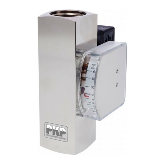
Overview 1: Process connection (outlet) 2: Device body 3: Switch contact and female socket or switch contact with cable 4: Switch point adjustment scale 5: Display housing with display scale and pointer mechanism 6: Process connection (inlet) Switch point adjustment scale: A scale is applied to the device body, to which the desired switch point can be adjusted. -
Page 5: Installation
This may result in serious injury to the user. if the mediums is contaminated by solids, a strainer must be installed before the device (e.g. SF00 or SF01 from PKP) DS02 Instruction manual 03/2020 page 5... - Page 6 Direction of flow: Only install the flow monitor in one of the positions displayed in the drawing. The medium must flow in the direction of the arrow (from a low to a high scale value). DS02 Instruction manual 03/2020 page 6...
-
Page 7: Connecting Devices Equipped With Reed Switches
Connecting devices equipped with Reed switches Reed switches are basically designed for small contact ratings. To connect a load with higher power consumption it is indispensable to use a contact protection relay (e.g. our series MSR01) If you connect directly a load to a Reed contact the following recommendations should be considered. - Page 8 Lamp Load Lamp loads consist e.g. by light bulbs, starting motors . WARNING: High current spikes at switching on, because the glowing spiral has low resistance at low temperature. Protective measures: (examples) Limitation of current by a resistor or preheating of the glowing spiral.
-
Page 9: Electrical Connection
250 V / 1 A / 30 VA, 3UT6 = Ex-SPDT T6* min load: 3 VA (2 m cable) * Exact max. switching capacity: see ATEX documents ** Protection class M12x1 plug for DS02.1 and DS02.2: IP65 DS02 Instruction manual 03/2020 page 9... -
Page 10: Contacts For Ds02.1 / Ds02.2
Contacts for DS02.1 / DS02.2: Switching contact with connector acc. to EN 175301-803: Normally Open (NOC) Change Over (COC) Switch position under no-flow condition Switch position under no-flow condition The ground-pin is not used The ground-pin is not used DS02 Instruction manual 03/2020... - Page 11 Switching contacts with plug connector M12x1 (mating connector not included in deliv- ery) Normally Open (NOC) Change Over (COC) Switch position under no-flow condition Switch position under no-flow condition Switching contact with cable: The individual cores of the cable are numbered according to the following connection dia - gram: Normally Open (NOC) Switch position under no-flow condition...
-
Page 12: Contacts For Ds02.2 / Ds02.3 / Ds02.4
Contacts for DS02.2 / DS02.3 / DS02.4 Switching contact with connector acc. to EN 175301-803: Normally Open (NOC) Change Over (COC) Switch position under no-flow condition Switch position under no-flow condition The ground-pin is not used The ground-pin is not used DS02 Instruction manual 03/2020 page 12... - Page 13 Switching contacts with plug connector M12x1 (mating connector not included in delivery) Normally Open (NOC) Change Over (COC) Switch position under no-flow condition Switch position under no-flow condition Switching contact with cable: The individual cores of the cable are numbered according to the following connection dia - gram: Normally Open (NOC) Change Over (COC)
-
Page 14: Setting The Switch Point
Setting the switch point The following instructions describe the procedure for a Normally Open Contact (NOC). The actual state (open or closed), can be determined using a continuity meter. 1. Loosen the switch contact set screws (1) using a screwdriver 2. -
Page 15: Troubleshooting Guide
Incorrect reduction fitting or Correct pipe diameter pipe diameter is too small Device is dirty Disassemble and clean the device Device is defective Remove device from system and contact PKP DS02 Instruction manual 03/2020 page 15... -
Page 16: Maintenance / Maintenance Plan
Degree of protection (IP-Code) Process connection Specification of Degree of protection connection material EN 175301-803 with gland Ø of connection cable: IP65 6-8 mm M12x1 (DS02.1/2) Plug connector M12x1 IP65 M12x1 (DS02.3/4) Plug connector M12x1 IP67 Cable IP67 Returns For returns please contact us: PKP Prozessmesstechnik GmbH Info@pkp.de... - Page 17 This ensures a bistable switch function at any time. An external pointing instrument is magnetically coupled to the float and indicates the flow rate. 20201026 PKP Prozessmesstechnik GmbH +49 (0) 6122-7055-0 • T +49 (0) 6122 7055-50 Borsigstr. 24 • D-65205 Wiesbaden info@pkp.de • www.pkp.de...
- Page 18 2X = SPDT for SPS application (for devices from 1/2") 3ST5 = Ex-N/O, T5 (100 °C), with 2 m cabel, not for DS02.1 all other wetted parts: brass 3ST6 = Ex-N/O, T6 (80 °C), with 2 m cabel, not for DS02.1 3UT5 = Ex-SPDT, T5 (100 °C), with 2 m cabel, not for DS02.1...
- Page 19 3UT6 = Ex-SPDT T6* min load: 3 VA (2 m cable) * Exact max. switching capacity: see ATEX documents ** Protection class M12x1 plug for DS02.1 and DS02.2: IP65 ATEX-designations: Contacts 3SM and 3UM for DS02.1/2.: Contacts 3ST5, 3ST6, 3UT5, 3UT6 for DS02.2/3/4.: ATEX II 2 G Ex ib IIC and ATEX II 2 D Ex ib IIIC ATEX II 2 G Ex mb IIC T6 Gb, ATEX II 2 D Ex tb IIIC T80 °C Db...
- Page 20 Please note that the switch-on points are higher due to the hysteresis. For applications where pressure surges are to be expected, please contact PKP! • Dirt traps SF00, SF01 • Protection relay MSR01 • M12 Plug connector PVC-cable SM12 PKP Prozessmesstechnik GmbH +49 (0) 6122-7055-0 •...
Need help?
Do you have a question about the DS02.1 and is the answer not in the manual?
Questions and answers