Table of Contents

Related Manuals for PKP DS05


Summary of Contents for PKP DS05
- Page 1 Instruction Manual DS05 Variable Area Flowmeter and Switch - with Glass Measuring Tube - PKP Prozessmesstechnik GmbH Borsigstraße 24 D-65205 Wiesbaden-Nordenstadt Tel.: ++49-(0)6122-7055-0 Fax: ++49-(0)6122-7055-50 Email: info@pkp.de...
-
Page 2: Table Of Contents
Do not use flow monitors with fast-switching valves. The series DS05 flow meter devices should not be deployed as the sole agents to prevent dangerous conditions occurring in plant or machinery. Machinery and plant need to be designed in such a manner that faulty conditions and malfunctions do not arise that could pose a safety risk for operators. -
Page 3: Overview
Qualified Personnel The DS05 devices may only be installed by trained, qualified personnel who are able to mount the devices correctly. Qualified personnel are persons, who are familiar with assembling, installation, placing in service and operating these devices and who are suit- ably trained and qualified. -
Page 4: Installation
do not install the flow monitor as a supporting part in a pipe system the medium must not carry solid bodies. Magnetic particles accumulate on the magnetic float and impair its function. Check corrosion and antifreeze agents from the application for compatibility. DS05 Instruction manual 03/2020 page 4... - Page 5 This may result in serious injury to the user. if the mediums is contaminated by solids, a strainer must be installed before the device (e.g. SF00 or SF01 from PKP) Direction of flow: Only install the flow monitor in one of the positions displayed in the drawing. The medium must flow in the direction of the arrow (from a low to a high scale value).
-
Page 6: Connecting Devices Equipped With Reed Switches
Capacitive Load Capacitive loads consist e.g. of long connection cables or capacitive consumers. WARNING: High current spikes at switching on (this will exceed the nominal current) Protective measures: (examples) Limitation of current by a resistor DS05 Instruction manual 03/2020 page 6... - Page 7 But it cannot be guaranteed that for specific applications more adequate Boucherot cells may exist. For Reed switches of 10 – 40 VA Voltage [V] Resistance [Ohm] Capacitance [nF] 1500 For Reed switches of 40 – 100 VA Voltage [V] Resistance [Ohm] Capacitance [nF] 1000 DS05 Instruction manual 03/2020 page 7...
-
Page 8: Electrical Connection
3ST6 = Ex-N/O, T6* cable) 1/4“ 3UT5 = Ex-SPDT, T5* 250 V / 1 A / 30 VA, 3UT6 = Ex-SPDT, T6* min load: 3 VA (2 m cable) * Exact max. switching capacity: see ATEX documents DS05 Instruction manual 03/2020 page 8... - Page 9 Switching contact with connector acc. to EN 175301-803: Normally Open (NOC) Change Over (COC) Switch position under no-flow condition Switch position under no-flow condition The ground-pin is not used The ground-pin is not used DS05 Instruction manual 03/2020 page 9...
- Page 10 Switching contact with cable: The individual cores of the cable are numbered according to the following connection dia - gram: Normally Open (NOC) Change Over (COC) Switch position under no-flow condition Switch position under no-flow condition DS05 Instruction manual 03/2020 page 10...
-
Page 11: Setting The Switch Point
6. Tighten the set screws of the switch contact using a flat-bladed screwdriver. When doing so, observe the correct tightening torque (0,4 Nm) of the screws. The set switch point corresponds to the switch-off point of the switch contact by decreas- ing flow. DS05 Instruction manual 03/2020 page 11... -
Page 12: Troubleshooting Guide
Incorrect reduction fitting or Correct pipe diameter pipe diameter is too small Device is dirty Disassemble and clean the device Device is defective Remove device from system and contact PKP DS05 Instruction manual 03/2020 page 12... -
Page 13: Maintenance / Maintenance Plan
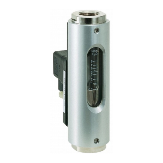
Maintenance / Maintenance plan Intervals for replacing wear parts DS05 type flow monitors require very little maintenance due to the small number of mov- ing parts. The intervals for the replacement of wear parts depend significantly on the oper - ating conditions as well as on the composition of the medium flowing through the device. - Page 14 Ex- version acc. to ATEX • Description: Typical application: The flowmeter and switch model DS05 works according to a The variable area flowmeters and monitors DS03 are used to modified variable area principle. measure and monitor continuous flow rates of low-viscosity The float is guided in a cylindrical measuring glass by means liquids or gaseous media.
- Page 15 1 = for water form A (DIN 43650), Measuring ranges: Ex-contact with 2 m cable DS05.1, DS05.1A and DS05.2: optional: cable connection 01 = 0,2–4 l/min (water) round plug M12 x 1 acc. to EN 50044 02 = 0,5–6 l/min (water) angle plug with LED or glow lamp 03 = 0,5–8 l/min (water)
- Page 16 ATEX II 2 G Ex mb II T5 & ATEX II 2 D Ex tD A21 IP67 T100 °C (with cable connection, Standard 2 m only) PKP Prozessmesstechnik GmbH +49 (0) 6122-7055-0 • T +49 (0) 6122 7055-50 Borsigstr. 24 • D-65205 Wiesbaden info@pkp.de •...
- Page 17 Please note that the switch-on points are higher due to the hysteresis. For applications where pressure surges are to be expected, please contact PKP! • Dirt traps SF00, SF01 • Protection relay MSR01 • M12 Plug connector PVC-cable SM12 PKP Prozessmesstechnik GmbH +49 (0) 6122-7055-0 •...
Need help?
Do you have a question about the DS05 and is the answer not in the manual?
Questions and answers