Table of Contents

Related Manuals for PKP DS25


Summary of Contents for PKP DS25
- Page 1 Instruction Manual DS25 All metal variable area flowmeter, insensitive to viscosity changes PKP Prozessmesstechnik GmbH Borsigstraße 24 D-65205 Wiesbaden-Nordenstadt Tel.: ++49-(0)6122-7055-0 Fax: ++49-(0)6122-7055-50 Email: info@pkp.de...
-
Page 2: Table Of Contents
The liability of the manufacturer expires in the event of damage due to improper use, non- observance of this operating manual, use of insufficiently qualified personnel and unauthorized modification of the device. DS25 Instruction Manual 08/2018 page 2... - Page 3 The series DS25 flow meter devices should not be deployed as the sole agents to prevent dangerous conditions occurring in plant or machinery. Machinery and plant need to be designed in such a manner that faulty conditions and malfunctions do not arise that could pose a safety risk for operators.
-
Page 4: Device Description
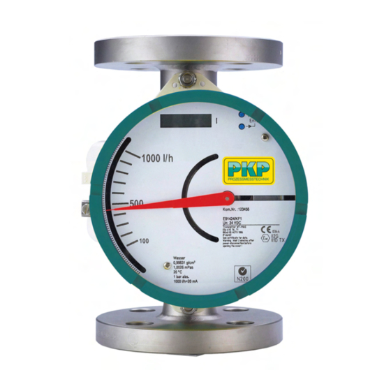
DIN • size of flange e.g. DN15 • Pressure range of flange and measuring tube e.g. PN40 • Material of wetted parts e.g. 1.4404 • Manufacturing code of flange manufacturer • Lot. No. • DS25 Instruction Manual 08/2018 page 4... - Page 5 Scale example for Display Scale example for Display with electronic transmitter DS25 Instruction Manual 08/2018 page 5...
-
Page 6: Installation In The Pipeline
Electrical Connection Please regard the drawings on the following pages. On the rear of the DS25 are two cable glands for round cables with a diameter of 6 to 9 mm • Unused glands must be closed with a blind plug M16x1.5. - Page 7 Units with a nominal voltage of 24 V may only be connected to a protected low voltage • circuit (SELV-E according to VDE0100/VDE 0106 or IEC 364/IEC 536). The DS25 indicator housing must be grounded to ensure electromagnetic interference • protection. This can be done by grounding the pipeline.
- Page 8 2 wire unit: 4 wire unit: DS25 Instruction Manual 08/2018 page 8...
-
Page 9: Connection Diagrams
Connection Diagrams DS25, 2-wire unit with limit switches and transmitter relay: DS25, 3-wire unit with limit switches and transmitter relay: DS25 Instruction Manual 08/2018 page 9... - Page 10 DS25, 4-wire unit with pulse output: DS25, 2-wire unit with HART-communication, with limit switches and transmitter relay: DS25 Instruction Manual 08/2018 page 10...
-
Page 11: Start Of Operation
If the state of operation changes, it might become necessary to establish a new scale. This depends on several factors: If the DS25 is operated in the given viscosity independent range, only the density of the float • as well as the operational density of the previous and new substance have to be considered. -
Page 12: Limit Switches
The terminals for the limit switches are on a small board on top of the transmitter case. Use of 2 standard limit switches: The MIN-MIN and MAX-MAX functions have been integrated at the factory as MIN-MAX switches in the DS25. The MIN-MIN or MAX-MAX function is set by adjusting the switching direction of the transmitter relay. - Page 13 To adjust the switching points, loosen set screws 1 and 2 and move them in the guide rail. The small red pointers (Limit switch MAX and Limit switch MIN) indicate the set value on the scale. DS25 Instruction Manual 08/2018 page 13...
-
Page 14: Electronic Transmitter
The set of the 20 mA point is shown on the scale. The flow cut off is positioned at 5 % of the end value. Below 5 % flow the current output shows 0 mA (4 mA). DS25 Instruction Manual 08/2018 page 14... - Page 15 Switching of current output 0-20 mA / 4-20 mA or vice versa • Indication of error messages • Manual adjustment • Service functions • Detection of float blockage • The setting of these parameters is done by two buttons. DS25 Instruction Manual 08/2018 page 15...
- Page 16 Unit x 1/100 The totalizer counts up to 99999999 or 9999999.9 or 999999.99 and is reset to zero. The next page shows the operating menu. The following describes selection and execution of functions. Menu: DS25 Instruction Manual 08/2018 page 16...
- Page 17 DS25 Instruction Manual 08/2018 page 17...
-
Page 18: Selection Of Indication Function (F11)
If "Temperature" is selected the unit can be set by function F15. The indicated value is the temperature in the indication unit. After changing the indicating function and measuring units the corresponding measuring unit label should be fixed on the right side next to the display. DS25 Instruction Manual 08/2018 page 18... -
Page 19: Setting The Unit (F12 / F13)
Setting the unit (F12 / F13) When ordering the transmitter two sets of metering units are available. It is not possible to switch between them. These two sets comprise the following metering units: DS25 Instruction Manual 08/2018 page 19... - Page 20 A sheet with stickers is included. Attention: When switching the mass/volume unit the totalizer is reset to zero. When changing the time unit the totalizer value remains unchanged. DS25 Instruction Manual 08/2018 page 20...
-
Page 21: Totalizer Reset (F14)
At the factory the display is set to degC indication. The selection of the indication is as follows: Note: If you press “↑" instead of “Enter”, you can return from the selected point to the previous menu without activating the displayed parameter. DS25 Instruction Manual 08/2018 page 21... -
Page 22: Setting Of Damping (F2-)
1 sec. The selection of the time constant is as follows: Note: If you press “↑" instead of “Enter”, you can return from the selected point to the previous menu without activating the displayed parameter. DS25 Instruction Manual 08/2018 page 22... -
Page 23: Selection / Adjustment 4-20 Ma / 0-20 Ma (F3-)
If the adjusting range does not suffice, change to display F32 or F33 by pressing ENTER when display shows F32 31 or F33 31, press ENTER again and continue adjusting at F32 00 or F33 00. DS25 Instruction Manual 08/2018 page 23... -
Page 24: Error Messages (F4-)
F32 or F33. WARNING: Since PKP doesn’t have any influence on the custom-designed connection the current output is not automatically adapted, if the connection is changed from 2 wire to 3 wire or vice versa . This must be manually carried out with the functions F32 and F33. -
Page 25: Manual Adjustment (F5-)
Calculate the new of flow rate to mm (on scale) relation based on original manufacturers calibration certificate. b) Place the DS25 (with the measuring tube) horizontally on a table (Note: the distance to any ferromagnetic parts must be at least higher than 25 cm!). - Page 26 After storage the new adjustment is permanently available and can be switched “on” or “off” by function F51. Note: When manually adjustment is active, the user is responsible for the measurement accuracy. Activating/deactivating manual adjustment table (F51) (*) -1 : manual adjustment OFF; -2 : manual adjustment ON DS25 Instruction Manual 08/2018 page 26...
- Page 27 In these cases the following steps have to be performed: a) Place the DS25 in line with the master meter in an installation allowing controlled flow with the process fluid at process conditions in a flow range from 5 % to 105 % of the expected flow range.
- Page 28 (this gives a real new flow scale without new calibration) or to order a new calibration by the manufacturer together with a new scale and EEPROM for the new fluid and/or new process conditions (this gives new adjustment plus new calibration). DS25 Instruction Manual 08/2018 page 28...
-
Page 29: Revision Indication (F61/F62)
During selection you can switch between 0/4 mA and 20 mA with the"→"-key. If you press “↑” instead of “Enter”, you can return from the selected point to the previous menu item without activating the displayed parameter. DS25 Instruction Manual 08/2018 page 29... -
Page 30: Switching Between Standard / Indicator On Extension (F64)
F64 allows switching between the standard calibration table and a calibration table of the remote version (option /A16 for high temperatures). The adjustment has to be performed according to the DS25 type (MS code). This is done as follows: Note: If you press “↑"... -
Page 31: Float Blocking Indication (F7-)
This value gets stored and will not be lost after power off / on the DS25 or after switching off / on the Float-Move-Detection-function. The stored value is typed over first after a renewed autozero. - Page 32 • Check Autozero value after approx. 80 seconds. • During the Autozero function it absolutely has to be respected that: the DS25 is not moved by touching or using the 2 buttons. • the pointer is protected against slipping. •...
- Page 33 If the plant has an extremely quiet flow (gases or liquids) ,the supervision range can be limited in the lower flow range. Normally greater flow (> 30 %) causes greater medium flow deviations. The duration of the supervision can be put to 15 minutes to reach a longer supervision time. DS25 Instruction Manual 08/2018 page 33...
- Page 34 Parameter setting Error message (F41) Factory defaults / Master Reset (F65) The DS25 is adjusted at delivery (Factory Setting): F71 - 1 Float-Move-Detection • F72 - 1 Lower limit value of the supervision area • F73 - 1 Supervision time (Time Out) 5 min •...
- Page 35 Float-Blocking-Indication (F7x) Function F71: On-/Off- switching of the float-blocking-indication Function F72: Selection of the lower limit value of the supervision range Function F73: Selection of the supervision time Function F74: Start Autozero function and storage DS25 Instruction Manual 08/2018 page 35...
-
Page 36: Service And Maintenance
Measuring tube, float The DS25 is maintenance-free. If contamination of the measuring tube impairs the mobility of the float, the tube and the float have to be cleaned. To do this, the DS25 has to be removed from the pipe. - Page 37 The power supply PCB of 4-wire units includes a fuse. For fuse replacement be sure to switch off the power supply. Only use fuses with the capacity and characteristic as imprinted on the fuse holder. DS25 Instruction Manual 08/2018 page 37...
- Page 38 • • • • • • • • • ...
- Page 39 ...
- Page 40 ...
- Page 41 ...
- Page 42 ...
- Page 43 ...
- Page 44 ...
- Page 45 ...
Need help?
Do you have a question about the DS25 and is the answer not in the manual?
Questions and answers