
Related Manuals for PKP DU06 Series


Summary of Contents for PKP DU06 Series
- Page 1 Instruction Manual DU06 Ultrasonic flowmeter with display PKP Prozessmesstechnik GmbH Borsigstraße 24 D-65205 Wiesbaden-Nordenstadt Tel.: ++49-(0)6122-7055-0 Fax: ++49-(0)6122-7055-50 Email: info@pkp.de...
-
Page 2: Table Of Contents
Table of Contents Safety Information..........................2 Functional description..........................3 Installation location..........................3 Electrical connection..........................4 Menu navigation...........................5 Output parameter <Output Parms> Menu 1..................5 Instrument parameter <Instrument Parms> Menu 2................7 Mathematical parameters <Math.Parms> Menu 3................9 Instrument test function <Instr. Test> Menu 4...................10 Error messages............................11 Functional check..........................11 Safety Information General Instructions To ensure safe operation, the device should only be operated according to the... -
Page 3: Functional Description
Qualified Personnel The DU06 devices may only be installed by trained, qualified personnel who are able to mount the devices correctly. Qualified personnel are persons, who are familiar with assembling, installation, placing in service and operating these devices and who are suitably trained and qualified. -
Page 4: Electrical Connection
Electrical connection Attention: Prior to the electrical connection of the device, it must be ensured that the sup- ply voltage matches that required and the supply voltage is switched off. Plug arrangement Power supply, current-, voltage-, frequency output 4 pole plug (included in delivery) Pin 1: 4-20mA / 0-10V / Freq.Out Pin 2: GND Pin 3: GND... -
Page 5: Menu Navigation
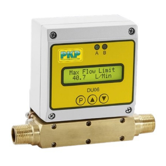
Menu navigation By help of a menu system the user can adapt the device to his application. The Menu has a simple structure and is easy to handle. The button <P> activates the menu. With the button <Arrow up > respectively <Arrow down > you can choose one or the four menu points Output Parms •... - Page 6 Maximum flow limit - Max Flow Limit This parameter dedicates, at which flow the max. value of the selected output signal is created. (4-20 mA, 0-10 V, Fout). So it is possible to adapt the upper limit of the measur - ing range to the individual requirement.
-
Page 7: Instrument Parameter
Instrument parameter <Instrument Parms> Menu 2 DU06 Modus, Flow meter - Totalisator - DU06 Mode Flow: the device works as flow meter Totalize: the device works as totalizer The added value of the totalizer is still achieved in case of power failure. A power failure can be indicated but the function Bat Check.Menu 2 - Page 8 Leak flow volume cut off - Low Flow Cut-Off If the absolute value of flow is smaller than Max Flow Limit * Low_Flow_Cut_Off, indic- ated flow value is 0. Low flow cut off can be adjusted between 0 % and 10 % of Max Flow Limit.
-
Page 9: Mathematical Parameters
Mathematical parameters <Math.Parms> Menu 3 Characteristic diagram K-Factor – K-Factor This function is used for adaption of the characteristic diagram up to formula Qkorr = Qist * K; Qist -measured flow; Qkorr -corrected flow; - absolute term (multiplicative) It is used if flow conditions have changed referring to the original calibration Advice: This function is protected due to a separate Code (KO_Code).Menu 3 -
Page 10: Instrument Test Function
Instrument test function <Instr. Test> Menu 4 Indication of supply voltage - Supply Voltage The device works like a Voltmeter and indicates the actual supply voltage. Puss button <P> to finish the measurement. Advice! The allowed voltage is: 24 VDC +/-15 %, max. Ripple 100 mV If low-grade power supply units are used, restricted function of the DU06 respectively inac - curate Measurement can appear.Menu 4 -
Page 11: Error Messages
Error messages Error 1: Echo Bad Very turbulent flow, or too high air content in the medium; no measurement possible. The reason may be that the medium generally has a high proportion of air, or the propor- tionate air is dispensed by turbulence in the measuring system. See point 6 (Selection of the installa - tion location). - Page 12 20190911 PKP Prozessmesstechnik GmbH +49 (0) 6122-7055-0 • T +49 (0) 6122 7055-50 Borsigstr. 24 • D-65205 Wiesbaden info@pkp.de •...
- Page 13 Pin 6: relay 1, N/C contact IP65 Protection class: 0,8...8 s, factory setting ca. 1,6 s Response time: Dimensions: adjustable in device Flow direction: PKP Prozessmesstechnik GmbH +49 (0) 6122-7055-0 • T +49 (0) 6122 7055-50 Borsigstr. 24 • D-65205 Wiesbaden info@pkp.de • www.pkp.de...
Need help?
Do you have a question about the DU06 Series and is the answer not in the manual?
Questions and answers