
Related Manuals for Wenglor X1TA101MHT88


Summary of Contents for Wenglor X1TA101MHT88
- Page 1 X1TA High Performance Distance Sensors Operating Instructions Translation of the Original Operating Instruction Subject to change without notice Available as PDF version only Status: 06.11.2018 www.wenglor.com...
- Page 2 7.4. A3 Error F/A3 Input 7.4.1. A3 Error 7.4.2. A3 Input 7.5. A1 Analog/Analog 7.6. Offset 7.7. Measuring rate 7.8. Laser 7.9. Read-Out 7.10. Interface (does apply to X1TA101MHT88) 7.11. Display 7.12. Language 7.13. Info 7.14. Reset 7.15. Password Index...
- Page 3 8. More Settings and Queries via the RS-232 Interface 8.1. Remote Control via a Terminal Program 8.2. Remote Control with Interface Commands 9. Maintenance Instructions 10. Proper Disposal High Performance Distance Sensors...
-
Page 4: Proper Use
Observe all applicable standards and safety precautions. 2007 3. EU Declaration of Conformity The EU declaration of conformity can be found on our website at www.wenglor.com in download area. RoHS UL Certified only in combination with the following wenglor connection cables: S23, S35, S88. -
Page 5: Technical Data
4. Technical Data Optical Data X1TA101MHT88 X1TA101MHV80 X1TA100QXT3 Working range 0,2…100,2 m 0,2…100,2 m 0,1…10,2 m Working range analog 0,2…100,2 m 0,2…100,2 m 0,2…10,2 m Measuring range 100 m 100 m 10 m Reference reflector/reflector sheet 4 × RQ100BA 4 × RQ100BA... - Page 6 Measuring Range: The Sensors’ measuring range is determined by object remission and the size of the reflector. Type of Reflector Mounting Distance X1TA101 X1TA100 5...100 m* RQ100BA 0,1...10 m 0,2...10 m RF505 0,2...40 m* 0,1...10 m RF508 0,2...40 m* 0,1...10 m RF258 0,2...40 m** 0,1...10 m...
-
Page 7: Connecting The Sensors
4.1. Connecting the Sensors X1TA101MHV80 X1TA101MHT88 X1TA100QXT3 Switching laser light off via pin connection: If the “La” pin is open or connected to negative, the laser is on. If positive voltage is applied, the laser is off. Connecting Cables M12 × 1, 8-pin Connecting Cables M12 ×... -
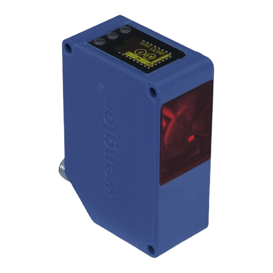
Page 8: Housing Dimensions
Screw M4 = 0,5 Nm 4.3. The Control Panel Display Control key 4.4. Complementary Products (see catalog) wenglor offers Connection Technology for field wiring. Suitable Mounting Technology No. Suitable Connection Technology No. Analog Evaluation Unit AW02 Reflector, Reflector Foil Protection Housing Set ZST-NN-02... -
Page 9: Mounting Instructions
Sensor. The Sensor must be protected against mechanical influences. Install the device such that its installation position cannot be inadvertently changed. The wenglor mounting system is recommended for installing the Sensor. Additionally a suiting reflector or reflex foil has to be mounted. -
Page 10: Default Settings
Important: Do not use any sharp objects to press the keys when configuring settings, because they might otherwise be damaged. Navigation up. Navigation down. Acknowledge the selected menu item (arrow points towards the display). Accept the selected setting, exit the menu (arrow points away from the display). 6.2. -
Page 11: Functional Overview
7. Functional Overview Mode U/I Analog Output Teach at 0 V at 10 V Pin Function T Object Switching Output A1 Switch/Analog T Background T Window Poti Hysteresis/ A2 Switch Window Size NPN/PNP NO/NC ON Delay Switching Output OFF Delay A3 Switch/Error/Input Impuls Extern T... -
Page 12: Pin Function
7.1. RUN The Sensor can be switched to the display mode by pressing the key. 7.2. Pin Function The Pin Function serves to determine the function of the pins A1 or A3. The pins can each take on different functions. - Page 13 Designation Function Key designation T Background Background-Teach-In Distance to the background is taught in by pressing the T key, so that the background can be suppressed: Sensor • Align the spot to the background (e.g. conveyor belt). Making point Hysteresis Breaking point Object...
- Page 14 Designation Function Key designation NPN/PNP Configuring the outputs The output is preset to PNP. Pressing the N key sets the output to push-pull. Pressing the N key again sets the output to NPN. The respective circuit diagram indicates how the output is set: Push-pull NO/NC Configuring the outputs...
-
Page 15: A3 Error F/A3 Input
7.4. A3 Error F/A3 Input 7.4.1. A3 Error The error output is activated if no light signal is returned to the Sensor. Designation Function Key designation NPN/PNP Output configuration „ The error output is set to PNP, push-pull or NPN by pressing the P or the N key. The respective circuit diagram is displayed. - Page 16 7.5. A1 Analog/Analog The measuring range for the analog output can be feely selected within the specified working range with rising of falling characteristic curve. The adjusted measuring range must have a value of at least 2 % of the total measuring range. Overall measuring range Rising characteristic curve Falling characteristic curve...
- Page 17 7.6. Offset The function offset serves to change the current measurement value to a certain other value. Here, the switching thresholds and the analog measurement ranges are changed as well. The offset can take place optionally via a menu or externally via Pin A3. Via menu Designation Function...
- Page 18 Without Offset equalization: In the diagram, the Sensor measures a distance of 5000 mm. The switching point is located 2000 mm distant, at 7000 mm. Switching Point 5000 mm 7000 mm [Distance measured with a meter ruler(mm)] With application of the offset equalization: Specification offset: 0 mm In the diagram, the Sensor measures a distance of 5000 mm.
-
Page 19: Measuring Rate
Transmitted light is deactivated or activated by pressing the or the key. For the products X1TA101MHT88 the laser light can be switched off via pin 5, by connecting pin 5 to 24 V. If Pin 5 has already been set as an RS-232 interface, the laser diode can be switched off with an interface command, in the menu or via the A3 input (see “7.2. - Page 20 7.9. Read-Out Which data will be read out to the display as measurement results are selected in the Read-Out menu. Designation Function Key designation DispMode Select display characteristics What will appear at the monitor during display mode operation is selected by pressing the or key: Distance: The states of the individual outputs appear at the display.
- Page 21 7.10. Interface (does apply to X1TA101MHT88) The basic settings for the interface are entered to the Interface menu. Designation Function Key designation Mode Basic interface settings One of the function types, namely Menu, Comm (default setting) or Continuous, is selected by pressing the ...
- Page 22 The individual values are read out consecutively to a single line. Only the values for the selected columns are read out. Functional Overview...
- Page 23 Explanation of the individual output values: Column 2: current distance: read-out of the respective current measuring distance in mm Column 3: statuses of the digital outputs: 0: not switched 1: switched Example: 1001 à error output and output 1 switched. Column 4: difference between current distance and the selected switching point (for each output) Example: Output 1: switching threshold at 2800 mm...
- Page 24 7.11. Display The display can be rotated and brightness can be adjusted with the help of the Display menu. Designation Function Key designation Rotated The display is rotated 180°. The display is rotated 180° by pressing the key. The display can be returned to its original position by pressing the same key once again.
- Page 25 7.15. Password Password settings can be entered in the password menu with the following four submenus. Designation Function Key designation Enable Switch Password Function On or Off The Enable menu is accessed by pressing the key, where you can activate or deactivate the password function by selecting Off or On.
- Page 26 Be sure to make a note of the new password before exiting the “change password” function! If the password is forgotten, it must be overwritten with a master password. The master password can be requested by e-mail from support@wenglor.com. Functional Overview...
-
Page 27: More Settings And Queries Via The Rs-232 Interface
• 9-pin M12 subminiature socket connector for direct connection to the RS-232 interface at the PC, or the utilized controller Connect the Sensor to the PC, the controller etc. via the wenglor S232W3 plug adapter. Install the plug adapter as follows: •... -
Page 28: Remote Control Via A Terminal Program
8.1. Remote Control via a Terminal Program 1. Connect the Sensor as described in chapter 8 above. 2. Set the Sensor to the Interface menu mode. à Select the “Interface” menu item. à Select “Mode”. à Select “Menu”. Alternatively: Select <Comm> and with F1, select remote control via Terminal-Program. The remote control via Terminal-Program can be ended with F4. -
Page 29: Remote Control With Interface Commands
• Do not clean with solvents or cleansers which could damage the device. 10. Proper Disposal wenglor sensoric GmbH does not accept the return of unusable or irreparable products. Respectively valid national waste disposal regulations apply to product disposal. High Performance Distance Sensors... - Page 30 Discover more innovation. For additional information about our products, please visit: www.wenglor.com...
Need help?
Do you have a question about the X1TA101MHT88 and is the answer not in the manual?
Questions and answers