
Related Manuals for Wenglor Y1TA OY1TA603P0003


Summary of Contents for Wenglor Y1TA OY1TA603P0003
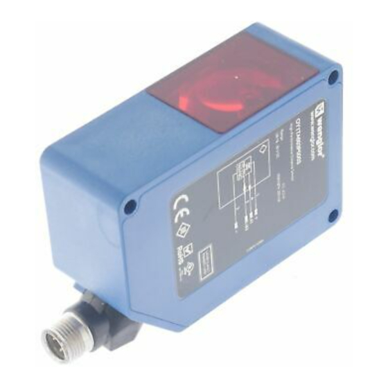
- Page 1 Y1TA OY1TA603P0003 High-Performance Distance Sensor Operating Instructions Translation of the Original Operating Instruction Subject to change without notice Available as PDF version only Status: 05.11.2018 www.wenglor.com...
-
Page 2: Table Of Contents
Index Use for Intended Purpose ........................4 Safety Precautions ..........................4 2.1. Safety Precautions ..........................4 2.2. Laser/LED warning ..........................4 EU Declaration of Conformity ......................5 Device Features ............................6 4.1. Connecting the Sensors ........................8 4.2. Housing Dimensions ..........................9 4.3. The Control Panel ..........................10 4.4. Complementary Products .........................10 Installation Instructions ........................11 Initial Start-Up ............................11 6.1. - Page 3 More Settings and Queries via the RS-232 Interface .................29 8.1. Remote Control via a Terminal Program ...................30 8.2. Remote Control with Interface Commands ..................31 Maintenance Instructions ........................31 10. Proper Disposal ............................31 High-Performance Distance Sensor...
-
Page 4: Use For Intended Purpose
Selected sensors are distinguished by WinTec (wenglor interference free technology). This technology allows black or shiny surfaces to be reliably detected even in extremely inclined positions. It is possible to mount several sensors next to or across from each other without them influencing each other. -
Page 5: Eu Declaration Of Conformity
3. EU Declaration of Conformity The EU declaration of conformity can be found on our website at www.wenglor.com in download area. RoHS High-Performance Distance Sensor... -
Page 6: Device Features
4. Device Features Y1TA100 Y1TA100 Y1TA100 Y1TA100 OY1TA603 Optical Data MHT88 MHV80 QXVT80 QXT3 P0003 at object Working range 0,1…10,1 m 0,1…10,1 m 0,1…10,1 m 0,1…10,1 m 0,2…6,2 m Measuring range 10 m 10 m 10 m 10 m Linearity 0,1…5 m 0,05 % 0,05 % 0,2 %... - Page 7 Measuring Range: The Sensors’ measuring range is determined by object remission. Maximum range of Y1TA OY1TA603P0003 Up to 10 m on white (90 % remission) Up to 6 m on white (90 % remission) Up to 5 m on gray (18 % remission) Up to 5 m on gray (18 % remission) Up to 3 m on black (6 % remission) Up to 3 m on black (6 % remission)
-
Page 8: Connecting The Sensors
4.1. Connecting the Sensors Y1TA100MHV80 Y1TA100MHT88 Y1TA100QXT3/OY1TA603P0003 Y1TA100QXVT80 Switching laser light off via pin connection: If the “La” pin is open or connected to negative, the laser is on. If positive voltage is applied, the laser is off. In the case of Y1TA100QXT3 and Y1TA100QXVT80, Pin “A1” can also be used as an analog output. The reference to ground here is Pin “–”... -
Page 9: Housing Dimensions
Connecting Cables M12 × 1, 4-pin Connecting Cables M12 × 1, 4-pin S23-2M S23-5M S23-10M S23-2MPUR S23-5MPUR Legend Encoder A Platinum measuring resistor Encoder B Supply Voltage + not connected Digital output MIN Supply Voltage 0 V Test Input Digital output MAX Supply Voltage (AC Voltage) Test Input inverted Digital output OK... -
Page 10: The Control Panel
Control key case. To find a remedy, see the mounting instruc- tions in case of glossy surfaces. 4.4. Complementary Products wenglor offers Connection Technology for field wiring. Suiting Connection Technology No. Suiting Mounting Technology No. Analog Evaluation Unit AW02 Protection Housing Set ZST-NN-02... -
Page 11: Installation Instructions
Sensor. The Sensor must be protected against mechanical influences. Install the device such that its installation position cannot be inadvertently changed. The wenglor mounting system is recommended for installing the Sensor. In order to obtain best possible results, the device’s optics should be aligned at a right angle to the direction in which the objects are conveyed. -
Page 12: Default Settings
6.2. Default Settings OY1TA603P0003 Y1TA A1: Switching output A1: Switching output Pin Function A2*: Switching output A3: Error output A3: Error output Teach Mode Object Object Switching threshold 1000 mm 1000 mm Hysteresis 20 mm 20 mm Window Size 50 mm 50 mm Outputs PNP/NPN... -
Page 13: Functional Overview
7. Functional Overview Mode U/I 1. Run Analog Output Teach at 0 V at 10 V 2. Pin Function 1. Run T Object Switching Output T Backgrnd. 3. A1 Switch/Analog 2. Pin Funktion T Window Poti Hysteresis/ Window Size NPN/PNP 4. -
Page 14: Pin Function
7.1. Run The Sensor can be switched to the display mode by pressing the key. 7.2. Pin Function The Pin Function serves to determine the function of the pins A1 or A3. The pins can each take on different functions. - Page 15 Designation Function Key designation T Backgrnd. Background-Teach-In Distance to the background is taught in by pressing the T key, so that the background Sensor can be suppressed: • Align the spot to the back- Making point ground (e.g. conveyor belt). Hysteresis •...
- Page 16 Designation Function Key designation NPN/PNP Configuring the outputs The output is preset to PNP. Pressing the N key sets the output to push-pull. Pressing the N key again sets the output to NPN. The respective circuit diagram indicates how the output is set: Push-pull NO/NC Configuring the outputs...
-
Page 17: A3 Error F/A3 Input
Designation Function Key designation Impulse Adjusting impulse duration – Object Impulse duration defines how long the Impulse duration output signal remains in the activated Impulse state. Impulse duration can be set to a value within a range of 0 to 10.000 ms On Delay by pressing the + or the –... -
Page 18: A1 Analog/Analog
7.4.2 A3 Input If Pin “A3” is used as input “Emitted light disengageable” or as input “Offset”, the input can be set as an in- verted or non-inverted input. Designation Function Key designation not invers Usage as non-inverted input ... - Page 19 Note: The menu item is only present for the Sensors Y1TA100QXVT80, Y1TA100QXT3 and OY1TA603P0003 if pin function “Analog” is set. Designation Function Key designation Mode U/I Analog output as current or voltage output The analog output can be set up as either a current or a voltage output by pressing the U or the I key. The corresponding symbol is displayed.
-
Page 20: Offset
7.6. Offset The function Offset serves to change the current measurement value to a certain other value. Here, the switch- ing thresholds and the analog measurement ranges are changed as well. The offset can take place optionally via a menu or externally via Pin A3. Via menu Designation Function... - Page 21 Without Offset equalization: In the diagram, the Sensor measures a distance of 5000 mm. The switching point is located 2000 mm distant, at 7000 mm. Switching Point 5000 mm 7000 mm [Distance measured with a meter ruler(mm)] With application of the offset equalization: Specification offset: 0 mm In the diagram, the Sensor measures a distance of 5000 mm.
-
Page 22: Measuring Rate
Example of application: A Y1TA100MHV80 is used in a high rack warehouse with varying ambient temperatures. To eliminate the tem- perature drift, a reference path of 1000 mm is specified to the Sensor as the specification offset. Through an external trigger Sensor, the specification offset is applied and given to the Sensor as the current distance. This ensures that the distance tallies with the value of the reference route with every trigger signal and thus, the vary- ing ambient temperature has no influence on the measurement values of the Sensor. -
Page 23: Read-Out
7.9. Read-Out Which data will be read out to the display as measurement results are selected in the Read-Out menu. Note: The menu item is only present for the Sensors Y1TA100QXVT80, Y1TA100QXT3 and OY1TA603P0003 if pin function “Analog” is set. The option “Analog” in only present for the sensors Y1TA100MHT88 and Y1TA100MHV80. -
Page 24: Interface
7.10. Interface (does apply to Y1TA100QXVT80 and Y1TA100MHT88) The basic settings for the interface are entered to the Interface menu. Designation Function Key designation Mode Basic interface settings One of the function types, namely Menu, Comm (default setting) or Continuous, is selected by pressing the ... - Page 25 The individual values are read out consecutively to a single line. Only the values for the selected columns are read out. High-Performance Distance Sensor...
- Page 26 Explanation of the individual output values: Column 2: current distance: read-out of the respective current measuring distance in mm Column 3: statuses of the digital outputs: 0: not switched 1: switched Example: 1001 à error output and output 1 switched. Column 4: difference between current distance and the selected switching point (for each output) Example: Output 1: switching threshold at 2800 mm...
-
Page 27: Display
7.11. Display The display can be rotated and brightness can be adjusted with the help of the Display menu. Designation Function Key designation Rotated The display is rotated 180°. The display is rotated 180° by pressing the key. The display can be returned to its original position by press- ing the same key once again. -
Page 28: Password
7.15. Password Password settings can be entered in the password menu with the following four submenus. Designation Function Key designation Enable Switch Password Function On or Off The Enable menu is accessed by pressing the key, where you can activate or deactivate the password function by selecting Off or On. -
Page 29: More Settings And Queries Via The Rs-232 Interface
Interface configuration: Adjustable baud rate, 8 data bits, no parity, 1 stop bit Plug connectors included with the wenglor S232W3 plug adapter: • 8-pin M12 plug connector for connecting the power supply and the outputs • 8-pin M12 socket connector for direct Sensor connection •... -
Page 30: Remote Control Via A Terminal Program
Connect the Sensor to the PC, the controller etc. via the wenglor S232W3 plug adapter. Install the plug adapter as follows: • Disconnect the 8-conductor connector cable (S80-xx) from the Sensor. • Connect the S232W3 plug adapter directly to the Sensor. -
Page 31: Remote Control With Interface Commands
• Do not clean with solvents or cleansers which could damage the device. 10. Proper Disposal wenglor sensoric gmbh does not accept the return of unusable or irreparable products. Respectively valid national waste disposal regulations apply to product disposal. High-Performance Distance Sensor...
Need help?
Do you have a question about the Y1TA OY1TA603P0003 and is the answer not in the manual?
Questions and answers