
Related Manuals for SMC Networks SI Unit


Summary of Contents for SMC Networks SI Unit
- Page 1 No.EX※※-OMU1006-B PRODUCT NAME SI Unit (PROFIsafe compatible) MODEL / Series / Product Number EX260-FPS1...
-
Page 2: Important
Original Instructions IMPORTANT This product is intended to be used in applications requiring the safe removal of the electrical energising supply to manifold mounted pneumatic valves. It is the user’s responsibility to determine if this product is suitable for the intended application and to specify the arrangement of the pneumatic valves appropriately to achieve the required safety function This manual is only valid for the EX260-FPS1 with the following hardware and firmware versions. -
Page 3: Table Of Contents
Contents IMPORTANT Safety Instructions 1. For your safety 1.1. General safety notes 1.2. Electrical safety 1.3. Safety of the machine or system 1.4. Directive and standards 1.5. Documentation 1.6. Abbreviations used 2. Product Summary 2.1. Features 2.2. Parts and description 2.3. -
Page 4: Safety Instructions
Safety Instructions These safety instructions are intended to prevent hazardous situations and/or equipment damage. These instructions indicate the level of potential hazard with the labels of "Caution", "Warning" or "Danger". They are all important notes for safety and must be followed in addition to International Standards (ISO/IEC) , and other safety regulations. - Page 5 Safety Instructions Caution 1.The product is provided for use in manufacturing industries. The product herein described is basically provided for peaceful use in manufacturing industries. If considering using the product in other industries, consult SMC beforehand and exchange specifications or a contract if necessary. If anything is unclear, contact your nearest sales branch.
- Page 6 Operator This operation manual has been written for those who have knowledge of machinery and apparatus that use pneumatic equipment and have full knowledge of assembly, operation and maintenance of such equipment. Please read this operation manual carefully and understand it before assembling, operating or providing maintenance to the product.
- Page 7 Caution ■Provide grounding to assure the noise resistance of the Serial System. Individual grounding should be provided close to the product with a short cable. ■NOTE ○Follow the instructions given below when designing, selecting and handling the product. The instructions on design and selection (installation, wiring, environment, adjustment, operation, maintenance, etc.) described below must also be followed.
- Page 8 Poor insulation (interference from another circuit, poor insulation between terminals, etc.) can lead to excess voltage or current being applied to the SI Unit, causing damage. Take appropriate measures against noise, such as using a noise filter, when the fieldbus system is incorporated into equipment.
- Page 9 Otherwise safety is not assured due to an unexpected malfunction or incorrect operation. Do not use solvents such as benzene, thinner etc. to clean the SI unit. They could damage the surface of the body and erase the markings on the body.
- Page 10 Fieldbus System/ Industrial IoT Cybersecurity In recent years, factories have introduced industrial IoT, building up complex networks of production machines. These systems maybe subject to a new threat, cyberattack. To protect the industrial IoT from cyberattacks, it is important to take multiple measures (multi-layer protection) for IoT devices, networks and clouds.
-
Page 11: For Your Safety
1.1.5. Do not carry out any repairs or modifications It is prohibited for the user to carry out repair work or make modifications to the SI Unit. The housing must not be opened. The SI Unit is protected against tampering by means of security labels. The security label is damaged in the event of unauthorized repairs or opening of the housing. -
Page 12: Electrical Safety
The SI Unit is designed for use with connecting cables that are less than 30 m long and do not go outside of a building. If these requirements are not met, then external measures must be taken to protect the unit. -
Page 13: Directive And Standards
1.4. Directive and standards The standards to which the SI Unit conforms are listed in the certificate issued by the approval body and in the EC declaration of conformity. 1.4.1. Intended use The EX260-FPS1 is designed exclusively for use in a PROFIsafe system and fulfils the PROFINET guidelines as defined by PI (PNO). -
Page 14: Product Summary
2. Product Summary 2.1. Features SI Unit The SI (Serial Interface) Unit represents a PROFIsafe on PROFINET IO-device for SMC pneumatic valves. It can be used to implement a safety function for the directly connected valves and has the following properties: Designed for use in safety systems up to SIL 3 according to EN 61508. -
Page 15: Parts And Description
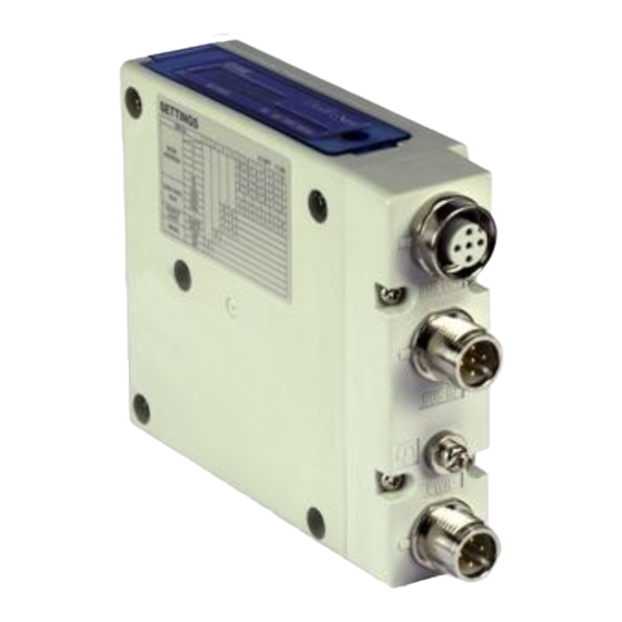
M12 4-pin socket, D-coded PROFINET connection PROFINET connection for Port 1 (BUS IN) M12 4-pin socket, D-coded Power supply for valves and power supply for logic of the SI unit Power supply connection M12 4-pin plug, A-coded Functional Earth terminal FE terminal... -
Page 16: Safe Power Supply (Output)
2.3. Safe power supply (output) The SI Unit has 1 safe digital output which can be used for valve power supply. Safe state The safety function of this product is to remove the electrical energising supply to the attached pneumatic valves. -
Page 17: Installation
Connect the valve manifold with the 2 screws on the SI Unit. (Hexagonal socket wrench size 2.5) Note: Tighten the screws while holding the SI unit and the valve manifold so that there is no gap between them. Tighten the screws with the tightening torque specified. -
Page 18: Wiring
Fig. 3-2 Top view of the valve manifold (SY3000 series) 3.2. Wiring Caution To prevent damage, all supply voltages to the SI Unit must be turned off (i.e. de-energized) before the modules are installed or removed. Connect the functional earth cable, the PROFINET cables and the power cable. - Page 19 3.2.1. PROFINET/Power connection The SI Unit has two PROFINET communication connectors. If only one connector is used, cover the unused connector with a seal cap so that the protection rating of IP67 is maintained. Caution Seal caps must be fitted to all unused bus connector ports to ensure an IP67 rating.
- Page 20 Note: When the autonegotiation function is disabled, you must use the correct network cable, refer to Fig 3-6, 3-7, 3-8. Auto crossover function is not available when the autonegotiation function is disabled. Auto crossover function shall be capable of switching over their twisted pair ports automatically between MDI and MDI-X pin assignment.
- Page 21 The SI Unit must be connected to FE (Functional Earth) to divert electromagnetic interference. Connect a grounding cable from the FE terminal screw on the SI Unit to the nearest functional earth point. The grounding cable should be as thick and short as reasonably possible.
-
Page 22: Commissioning
4.1.1. GSD file and symbol files In order to configure the SI Unit with your PROFIsafe controller software the appropriate GSD file is required. The GSD file contains all of necessary information to configure the SI Unit on your PROFIsafe controller software. -
Page 23: Safe Valve Power Module
4.3. Safe valve power module The SI Unit occupies 4 bytes of input data and 5 bytes output data for safety output and PROFIsafe communication. The “Safe valve power” module has PROFIsafe parameters as defined in Section 4.4. Table 4-3 Details of “Safe valve power” module... -
Page 24: Valves (32Coils) Module
4.5. Valves (32coils) module The SI Unit occupies 4 bytes of output data for valves. The order of valve coils starts at the SI Unit from left to right. Byte Output data Valve coils 0-7 Valve coils 8-15 Valve coils 16-23 Valve coils 24-31 Fig. -
Page 25: Specifications
5. Specifications Table 5-1 EX260-FPS1specifications Item Description General Dimensions (W x L x H) mm 28.2 x 102.4 x 78.0 Weight 200 g or less Housing material Rated voltage 24 VDC Supply interruption for no loss of function 1 ms and less IP67 (when fully installed or fitted with protective cover) Protection class (complies with IEC 60529) - Page 26 Table 5-1 EX260-FPS1specifications (continued) Solenoid valve Output type PNP (negative common) Max. number of solenoid valves Solenoid valve with surge voltage suppressor of 24 VDC and Connected load 0.95 W or less (manufactured by SMC) SY series SY3000, SY5000, SY7000 Applicable valve series JSY series JSY1000, JSY3000, JSY5000 Over current protection...
-
Page 27: Indication And Setting
6. Indication and setting 6.1. LED indicators The LED indicators are arranged on the SI Unit as shown in the illustration below. Designation Description Colour System fault Bus fault A combination of Link LED and Act LED Green Orange L/A1... - Page 28 6.1.1. SF and BF indicators Table 6-1 SF and BF indicators Meaning No fault (The SI Unit is currently exchanging data with the controller without errors) Faulty or no connect message frame (although the SI Unit is physically connected to an Ethernet) ●Configuration is defective, or initial commissioning has not been completed...
- Page 29 6.1.3. PWR indicator Table 6-3 PWR indicator PWR voltage Meaning <16 V PWR is not present Green Flashing 16 V…19 V PWR is below the permissible voltage range. Green ON 19 V…33 V PWR is present Red Flashing 33 V…40 V PWR is above the permissible voltage range.
-
Page 30: Production Label
6.2. Production label Product number MAC address Firmware and Hardware version Firmware version (FW): 1.0.x (X is a number 0 or more) Hardware version (HW): 03 and higher Fig. 6-2 Production label 6.3. PROFIsafe address switch An eight-bit DIP-Switch is provided for the F_Address of PROFIsafe. The switch setting is only checked at power-up. -
Page 31: Accessories
7. Accessories 7.1. Seal cap Seal caps can be used with the EX260-FPS1. Mount the seal cap in the unused M12 socket connector. IP67 is satisfied by using the seal cap properly. Model No.: EX9-AWTS (M12 connector for socket 10 pieces) Fig. -
Page 32: Dimensions
8. Dimensions The following figure shows the dimensions of EX260-FPS1. - 31 - No.EX※※-OMU1006-B... -
Page 33: Troubleshooting
The SI Unit is connected to the Ethernet network, but the following problem has occurred ●Check the cable connection ●The SI Unit is not connected to the ●Check network settings PROFINET Controller BF indicator is Red flashing ●Check PROFINET controller is active ●Configuration is defective... - Page 34 Possible cause Remedy Check the PROFIsafe configuration No safe communication and F-Address switch SF indicator is The SI Unit is not parameterized by Check the PROFIsafe configuration Red flashing at 2Hz the Safe controller The parameterization is not Check the configuration...
- Page 35 Connection between the SI Unit Check the connection between the and valve manifold is defective SI Unit and valve manifold The SI Unit and valve output Check the output type(PNP/NPN) type(PNP/NPN) do not match the SI Unit and valves. ●Reset the power supply Self-test has failed ●Check the diagnostic message...
-
Page 36: Acknowledgment And Restart
9.2. Acknowledgment and restart ●Remove the cause of the error ●Acknowledge the diagnostic message ●Parameterization errors cannot be acknowledged. In this case, proceed as follows: - Check the parameterization - Adapt the parameterization - Download the new data record For instructions on error acknowledgment, refer to the documentation for the controller used. WARNING: Hazardous machine state/unintentional machine startup The acknowledgment of an error can result in a hazardous state as well as unintentional machine startup since the safe input is immediately returned to the operating state. -
Page 37: Appendix A: Glossary For Profisafe
Appendix A: Glossary for PROFIsafe A definition of PROFIsafe terms is also provided in the PROFIsafe profile. Cyclic Redundancy Check A cyclic redundancy check is used to verify the validity of the process data contained in the safety telegram, check whether the assigned address books are correct, and verify the safety-related parameters. This value is part of the safety telegram. - Page 38 F-Slave Failsafe slave F_Source_Address F-Parameter, PROFIsafe source address; address of the safe controller (Refer to also "F-Parameter") F-System Failsafe system A failsafe system is a system that remains in the safe state or immediately enters a safe state when specific failures occur.
-
Page 39: Appendix B: Parameters For Profisafe
Appendix B: Parameters for PROFIsafe F-parameters The values indicated in italics in Table are preset by the system and cannot be modified manually. Table B-1 Overview of the F-Parameters for the module F-Parameter Default value Description Safety integrity (SIL according to IEC61508) of the module. Safety functions up to SIL 3 can be achieved with the module. -
Page 40: Appendix C: Checklists
Enter the device type and/or the equipment identification for the relevant module. Version: HW/FW enter the hardware and firmware version of the module as shown on the label on the SI Unit. For details of the label on the SI Unit, refer to Section 6.2. - Page 41 Table C-2 Planning Checklist for planning the use of the module Device type/equipment identification Version: HW/FW Date Creator Test engineer Remark Requirement (mandatory) Remark Has the current user manual for this product been used as the basis Revision: for planning? Are the valve manifold and selected valves approved for connection to the module (according to the technical data and parameterization options?)
- Page 42 Table C-3 Assembly and Electrical Installation Checklist for Assembly and Electrical Installation of the module Device type/equipment identification Version: HW/FW Date Creator Test engineer Remark Requirement (mandatory) Remark Was assembly completed according to the specifications (specifications from the planning phase or according to the user manual)? Are all unused ports fitted with a seal cap? Do the cable cross sections and installation correspond to the...
- Page 43 Table C-4 Commissioning and Parameterisation Checklist for commissioning and parameterization of the module Device type/equipment identification Version: HW/FW Date Creator Test engineer Remark Requirement (mandatory) Remark Was commissioning completed according to the specifications (specifications from the planning phase or according to the user manual)? During commissioning, is it ensured that any person intentionally starting hazardous movements can only do so with a direct view of...
- Page 44 Table C-5 Validation Checklist for validation Device type/equipment identification Version: HW/FW Date Creator Test engineer Remark Requirement (optional) Remark Have all the mandatory requirements for the "Planning" checklist been met? Have all the mandatory requirements for the "Assembly and electrical installation" checklist been met? Have all the mandatory requirements for the "Commissioning and parameterization"...
-
Page 45: Appendix D: Safety Characteristics
Appendix D: Safety Characteristics Operation Value Item >90% Hardware Fault tolerance <1 FIT Probability of dangerous failure per hour Hardware classification Type B Safety Level SIL3 / PL e Mission Time 20 years - 44 - No.EX※※-OMU1006-B... -
Page 46: Appendix E: Ex260-Fps Timing Values
Appendix E: EX260-FPS Timing Values Typical timing values of SMC EX260-FPS1 Reaction time for safety function : < 6 ms Non safe valve output delay : 2 ms single fault diagnostic detection time : < 15 min Device acknowledge time (DAT) : <= 10 ms For calculating/determining the response time (safety function response time –... -
Page 47: Appendix F: Failure Modes
Appendix F: Failure modes The function of the product is to safely control the switching off of the attached pneumatic valves. Hazards and harmful events that could compromise this function need to be responded to as defined below. Failure Cause Detected by Action Turn off supply to valves by safety switches,... - Page 48 Revision history Revision A Original Instructions” in page 2. Add the “ Change the design in Fig. 6-2. Revision B X222 & FPS2 versions removed, note added about connection of FE to M3 terminal, high voltage threshold changed from 32 V to 33V, HW version updated to 03, product label updated, anti-tamper label added, power supply current rating added, yellow deleted from L/A &...
Need help?
Do you have a question about the SI Unit and is the answer not in the manual?
Questions and answers