Sign In
Upload
Download
Table of Contents
Contents
Add to my manuals
Delete from my manuals
Share
URL of this page:
HTML Link:
Bookmark this page
Add
Manual will be automatically added to "My Manuals"
Print this page
×
Bookmark added
×
Added to my manuals
Manuals
Brands
Charlton & Jenrick Manuals
Indoor Fireplace
480E
Installation and operation instructions manual
Charlton & Jenrick 480E Installation And Operation Instructions Manual
Led electric fire
Hide thumbs
1
2
3
4
5
6
7
8
9
10
11
12
13
14
15
16
17
18
19
20
21
22
23
24
25
26
27
28
29
30
31
32
Table Of Contents
33
page
of
33
Go
/
33
Contents
Table of Contents
Bookmarks
Table of Contents
Table of Contents
Important Safety Information
Technical Specifications
Parts and Hardware
Appliance Dimensions
Locating the Appliance
Installation Instructions
Metal Trim Installation
Installation of Hanging on the Wall
Installation into the Mantel
Operating Instructions
6A. Manual Control Panel
Main Power Switch
6B. Remote Controls
Flame Effect
Turn On/Off
Fuel Bed Colour
Mood Light
Normal Mode
Count down Timer
Daily Timer Heating
Set up Day, Time and Comfortable Temperature
Adjusting the Set Temperature
To Check Your Daily Timer Settings
Week Timer Heating
Adaptive Start Control
Set up the Communication between the Remote and Appliance
Window Open Detection
Resetting the Code for Remote Control
Resetting the Thermal Cut out
Cleaning the Fireplace
Remote Handset Battery Replacement
Maintenance
Others
Advertisement
Quick Links
1
Parts and Hardware
2
Installation Instructions
3
Operating Instructions
4
6B. Remote Controls
Download this manual
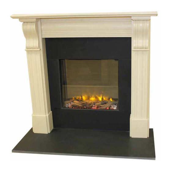
LED Electric Fire
Model No. 480E/780E/890E/1500E
INSTALLATION AND OPERATION INSTRUCTIONS
Please read the instructions carefully before installation or
use and keep for future reference
Table of
Contents
Previous
Page
Next
Page
1
2
3
4
5
Advertisement
Table of Contents
Need help?
Do you have a question about the 480E and is the answer not in the manual?
Ask a question
Questions and answers
Related Manuals for Charlton & Jenrick 480E
Indoor Fireplace Charlton & Jenrick 4D Ecoflame 1250E Installation And Operating Instructions Manual
Led electric fire (28 pages)
Indoor Fireplace Charlton & Jenrick 4D Ecoflame 1250E Installation And Operating Instructions Manual
Led electric fire (28 pages)
Indoor Fireplace Charlton & Jenrick INFINITY 480 BF Owner's Manual
Natural gas fireplace (41 pages)
Indoor Fireplace Charlton & Jenrick 890E Installation And Operation Instructions Manual
Led electric fire (33 pages)
Indoor Fireplace Charlton & Jenrick 2000 Plus Extra Remote Owner's Manual
(33 pages)
Indoor Fireplace Charlton & Jenrick PARAGON P9 Owner's Manual
Paragon gas fire (32 pages)
Indoor Fireplace Charlton & Jenrick infinity 890 BF Owner's Manual
(32 pages)
Indoor Fireplace Charlton & Jenrick PARAGON FOCUS 18 HE Owner's Manual
(32 pages)
Indoor Fireplace Charlton & Jenrick Paragon P3 Owner's Manual
(28 pages)
Indoor Fireplace Charlton & Jenrick PARAGON 2016 Owner's Manual
(28 pages)
Indoor Fireplace Charlton & Jenrick Solstice Operating Manual
(9 pages)
Indoor Fireplace Charlton & Jenrick EF16NC Installation Instructions & Operating Manual
(8 pages)
Indoor Fireplace Charlton & Jenrick Paragon SlimLine 3 Slide Owner's Manual
(32 pages)
Indoor Fireplace Charlton & Jenrick PARAGON 2000 Plus SLIDE CONTROL Owner's Manual
(32 pages)
Indoor Fireplace Charlton & Jenrick PARAGON P5 BF Owner's Manual
(32 pages)
Indoor Fireplace Charlton & Jenrick Polaris 620 Installation And Operation Instructions Manual
Led electric fire (26 pages)
This manual is also suitable for:
780e
890e
1500e
Table of Contents
Print
Rename the bookmark
Delete bookmark?
Delete from my manuals?
Login
Sign In
OR
Sign in with Facebook
Sign in with Google
Upload manual
Upload from disk
Upload from URL


Need help?
Do you have a question about the 480E and is the answer not in the manual?
Questions and answers