Charlton & Jenrick 4D Ecoflame 1250E Installation And Operating Instructions Manual
Led electric fire
Hide thumbs
Also See for 4D Ecoflame 1250E:

Related Manuals for Charlton & Jenrick 4D Ecoflame 1250E


Summary of Contents for Charlton & Jenrick 4D Ecoflame 1250E
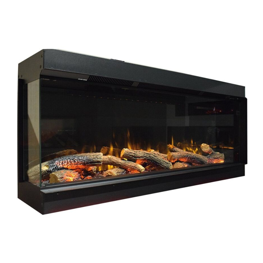
- Page 1 LED Electric Fire Model: 4D Ecofla me 1250E/1500E/1800E INSTALLATION AND OPERATING INSTRUCTIONS Please read the instructions carefully before installation or use and keep for future reference.
- Page 3 Importa nt Sa fe ty Informa tion ………………………………………………… Te chnica l S pe cifica tions ……………………………………………………… P a rts a nd Ha rdwa re …………………………………………………………… Applia nce Dime ns ions ………………………………………………………… Ins ta lla tion Ins tructions ……………………………………………………… Ope ra ting Ins tructions ………………………………………………………… Ma nua l Control P a ne l ……………………………………………………...
- Page 4 1.1 Read all the instructions carefully before using the appliance . 1.2 For indoor use only. This a pplia nce is not s uita ble for us e outs ide The hous e 1.3 Do not us e this a pplia nce in the imme dia te s urroundings of a ba th, a s howe r or a s wimming pool.
- Page 5 not play with the appliance. Cleaning and user maintenance shall not be made by children without supervision. 1.14 Children and vulnerable people must be always supervised when using this appliance, as some parts can become very hot and cause burns. A suitable fire gua rd mus t be fitte d for this purpos e .
- Page 6 At minimum heat output (elmin): 12W In standby mode (elSB): 0.49W Type of Heat Output / Room Temperature Control S ingle s ta ge he a t output a nd no room te mpe ra ture control Two or more ma nua l s ta ge s , no room te mpe ra ture control With me cha nic the rmos ta t room te mpe ra ture control With e le ctronic room te mpe ra ture control Ye s...
- Page 7 Power Cord Bracket (1pc) Installer must fit before ST4*40 Screw (4pcs) Wall Plug (18pcs) leaving appliance Lowe r Bra cke ts (2pcs ) To be used when the Wall Edging Strips (2pcs) Edging Strips (2pcs) Hanging Bracket (J) is used Wall hanging bracket is attached on fire box (1pc) 1250E (1pc)
-
Page 8: Preparation Before Installation
Simplifie d Ins truction (1pc) Instruction Manual (1pc) Unit: mm Mode l 1250E 1250 1280 1500E 1500 1530 1800E 1800 1830 5.1 PREPARATION BEFORE INSTALLATION Tools Required A s cre wdrive r, a s pirit le ve l a nd drill will be ne e de d. - Page 9 Prepare the Appliance Your new electric fire pla ce ma y be ins ta lle d virtua lly a nywhe re in your home . Howe ve r, whe n choos ing a loca tion, e ns ure tha t the ge ne ra l ins tructions a re followe d: For be s t re s ult, ins ta ll out of dire ct s unlight, wa te r, or ve ry da mp a ir.
- Page 10 Front view (only the front window is visible) When you unpack the appliance, you will notice that the side panels have been fixe d on the a pplia nce , which ma ke s the a pplia nce vis ible on only one front s ide .
- Page 11 5.2 Install ing the Appliance The following is only given as a general guide because it can be installed in so many ways, provided you ensure electric connections are safely made in accordance with the codes, various materials can be used for the framework and cladding.
- Page 12 Cladding the framework note: hard surfaces can amplify sound consider adding some underlay or similar to the inside surface of the cladding Wall Mounted Installation Re move the wa ll bra cke t from the re a r of the a pplia nce , a nd pla ce it horizonta lly a ga ins t the wa ll.
-
Page 13: Preparation Before Use
Mount the appliance carefully on the hooks of the wall bracket, secure the appliance To the wall bracket with the screws provided, one into each end Use four screws provided to fix the bottom bra cke ts to the corre s ponding hole s on the unde rs ide of a pplia nce a djus ting the bra cke ts pos ition to e ns ure the a pplia nce is plumb with the wa ll. - Page 14 the manual on/o ff NOTE: To use both remote and manual functions, switch must be in 'ON' position. To prevent the product becoming too hot, there is 10s delay when turning on the heater and a 10s delay when turning o ff the heater fan. Batteries Ensure that the handset batteries are new and inserted correctly.
- Page 15 6a .4 FUEL BED: P re s s button FUEL BED to s e le ct 14 diffe re nt fue l be d colour e ffe cts a nd OFF s e tting. If the fue l be d wa s turne d off by pre s s ing button LIGHTS ON/OFF a nd the fue l be d wa s not a t OFF, the fue l be d e ffe ct will be me moris e d.
- Page 16 Before Day/Time Set Up 6b.1 The screen shown to the right is when the remote controls is in standby mode Turn on/o ff 6b.2 P re s s to turn on/off the a pplia nce . Flame Effect After Day/Time Set Up 6b.3 P re s s to e nte r the fla me e ffe ct a djus tme nt s cre e n.
- Page 17 NOTE: It is normal for the fan heater to stop running for periods of time. This happens because the room temperature is at or above the temperature set on the remote control. The turned o ff after 10s if heater indicator will be you have the fl...
- Page 18 6b.20 Press until shows at the upper right corner of the screen, then enter the daily timer heating mode. 6b.21 Hold the button for 6 seconds to enter the daily timer setting. Up to 3 heating start time periods can be set. Press ' ' or ' ' to choose hour or minute,...
- Page 19 6b.27 Hold button for 6 seconds to enter the weekly timer setting. ' to move the cursor (a fla s hing Press ' ' or ' unde rline ), pre s s the button in the corre s ponding we e k pos ition to s e le ct (the cha ra cte r is highlighte d) or ca nce l (the cha ra cte r is dis pla ye d norma lly) the curre nt s e tting.
- Page 20 Window Open Detection 6b.34 When the transmitter detects a rapid drop in room temperature, it will be judged as a window open, the warning icon will be displayed and the heater will be turned off a utoma tica lly. the indoor te mpe ra ture ha s ris e n or a ma nua l 6b.35 Afte r ove rride of the wa rning (by ope ra ting re mote control) ha s be e n done the fire will re turn to norma l working s ta te .
- Page 21 6b.43 Ensure the batteries are inserted with the correct polarity. 6b.44 If the remote is to be unused for a long period, the batteries should be removed. 6b.45 The terminals within the remote must not to be short-circuited. Resetting the Thermal Cut Out a pplia nce is fitte d with a n Ele ctronic S a fe ty Control (E.S .).
- Page 22 front glass panel should always be completely dried with a clean, lint-free cloth or paper towel. Abra s ive cle a ne rs s hould not be us e d on the gla s s pa ne l. Caution: Liquids s hould not be s pra ye d dire ctly onto a ny s urfa ce of the unit.
- Page 24 Environment Meaning of crossed –out wheeled dustbin: Electrical appliance should not be disposed as unsorted municipal waste. Separate collection facilities should be used in the disposal of electrical appliances. Contact your local government for the information about the available collection systems.
- Page 28 Charlton & Jenrick Ltd Unit D, Stafford P a rk 2, Te lford, S hrops hire , TF3 3AR Te l: (0845) 5195 991 Fa x: (0845) 5195 992 www.cha rltona ndje nrick.co.uk...
Need help?
Do you have a question about the 4D Ecoflame 1250E and is the answer not in the manual?
Questions and answers