
Related Manuals for Invacare NordBed Ultra


Summary of Contents for Invacare NordBed Ultra
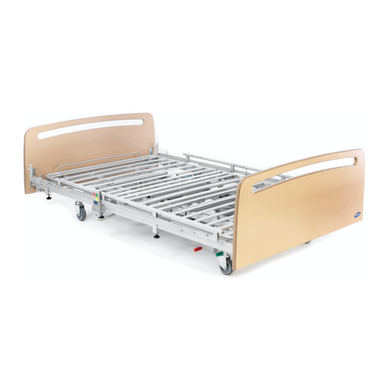
- Page 1 Invacare® NordBed™ NordBed™ Ultra, NordBed™ Optimo, NordBed™ Optimo Wide en Bed Service Manual PROVIDER: Keep this manual. The procedures in this manual MUST be performed by a qualified technician.
- Page 2 All rights reserved. Republication, duplication or modification in whole or in part is prohibited without prior written permission from Invacare. Trademarks are identified by ™ and ®. All trademarks are owned by or licensed to Invacare Corporation or its subsidiaries unless otherwise noted.
-
Page 3: Table Of Contents
Contents 1 General ......... 4 1.1 Introduction . -
Page 4: General
CAUTION Find the user manual on Invacare’s website or contact Indicates a hazardous situation that could your Invacare representative. See addresses at the end result in minor or slight injury if it is not of this document. -
Page 5: Safety
G Castor with central brake pedal delivered with the accessory. H Height adjustment actuator, upper half – Additional manuals can be ordered from Invacare. See addresses at the end of this I Back section actuator document. J Control unit – Due to regional differences, refer to your... -
Page 6: Setup
– Check all parts for shipping damage before use. – In case of damage, do not use the product and contact your Invacare provider for further instructions. Rotate the locking pin and allow it to engage with the 3.2 Installing bed ends bed end on both sides. -
Page 7: Bed End Brackets
Setup 3.2.3 Bed end brackets 1. If applicable, dismount the side rails, bed ends and lifting pole. Depending on the bed end to be mounted, it might be 2. To extend the bed in the foot end: required to pre-mount or change the bed end brackets. Mounting a. -
Page 8: Accessories
Invacare® NordBed™ 4 Accessories 3. Guide the three gliding shoes B (in the end of the side rail bars) up into the bed end guideways, until they have all passed the locking pin D. 4. Repeat steps 2 and 3 to mount the other side of the 4.1 Side Rails... -
Page 9: Installing The Torill Side Rail
Accessories 4.1.4 Installing the Torill side rail WARNING! Risk of entrapment / suffocation There’s a risk of entrapment or suffocation between side rail and bed end. – Never install the short and the long version of the side rail on the same bed. One side rail per side of bed –... - Page 10 Invacare® NordBed™ Charging the batteries WARNING! Risk of explosion Old or faulty batteries may generate an explosive gas mixture during charging. – The battery box is provided with vents to ensure adequate ventilation of the box. Do not block or cover the vents, as this may result in pressure built-up and the risk of explosion.
-
Page 11: Transportation And Storage
Transportation and Storage 5 Transportation and Storage 5.1 Disassembly of mattress support platform 1. Lock the brakes. 2. Remove bed ends, side rails and other accessories while the bed is in a suitable working height. 3. Lower the bed to the lowest height. 4. -
Page 12: Disassembly Of Base
Invacare® NordBed™ 5.2 Disassembly of base NordBed Optimo and NordBed Optimo Wide 105 cm only One after another, tip the two halves gently onto the floor and to an upright position onto the bed end brackets. Lock the short lifting mechanism by pulling up the lever with the red locking cam and pushing the locking cam firmly over the tube A. -
Page 13: Assembly Of Base
Transportation and Storage Pivot the short lifting mechanism up to a vertical position and lift it off by holding on the two square tubes A and E. Mount the long lifting mechanism by fitting the axles in the yellow marked cut-outs on the corner brackets of the base frame. -
Page 14: Assembly Of Mattress Support Platform
Invacare® NordBed™ 5.4 Assembly of mattress support platform Pivot the short lifting mechanism down into a horizontal position and hold it in place on square tube Unwind the cables from tube A, remove the hand A. Lift up the long lifting mechanism at blue marked... - Page 15 Transportation and Storage One after the other, push the two halves to the center of the bed and ensure the side tubes are properly Detach the control unit by pushing it up and sliding it aligned and connected. towards the foot end of the bed. On the control unit turn the lock 90 degrees counter-clockwise to open the lid and remove it.
-
Page 16: Transport Position
Invacare® NordBed™ Attach the control unit by sliding it onto the bracket and pushing it down to lock it in place. IMPORTANT! – If actuators have been reconnected or newly connected to the control unit, the system Place the two hooks of the green marked half (lower must be reset to ensure proper function. - Page 17 Transportation and Storage 5. Lift the two halves of the mattress support platform of the base frame. 6. Assemble the mattress platform. See 5.4 Assembly of mattress support platform, page 14 1657009-A...
-
Page 18: Servicing
6.2.1 Checklist - After relocation A service contract can be made in the countries, where Checkpoints Invacare has its own sales company. In certain countries Check that the lifting mechanisms are properly Invacare offers courses in service and maintenance of the engaged in their lower pivoting points on the base bed. -
Page 19: Cleaning Intervals
Servicing 6.3.4 Cleaning in automatic washing systems IMPORTANT! Wrong fluids or methods can harm or damage IMPORTANT! the product. Only certain components of the product tolerate – All cleaning agents and disinfectants used cleaning in automatic washing systems or with must be effective, compatible with one high pressure cleaning equipment. -
Page 20: After Washing
Invacare® NordBed™ • Bed placed on its castors To open the control unit, turn the lock 90 degrees counter-clockwise and remove the lid. 1. Bring the bed into sitting position (raised back section and thigh section with tilted mattress support platform) using the ErgoMove™ function on the hand control. -
Page 21: Wiring
Servicing 6.5 Wiring IMPORTANT! Ensure the cables are mounted and routed correctly – Make sure cables do not touch the floor and cannot block the castors. – Make sure cables cannot get squeezed by moving parts during operation. For the correct routing of the cables between the actuators and the control unit see the following pictures. 1657009-A... -
Page 22: Service Functions On Standard Hand Control
Invacare® NordBed™ 6.6 Service functions on standard hand Service mode control To enter or exit the service mode: 1. Press buttons B, C, p and qat the same time for 3 seconds. In service mode the display A shows a symbol D , a movement counter E and a status indicator F of the selected actuator and additional functions are available. - Page 23 Notes...
- Page 24 Invacare Sales Companies Ireland: United Kingdom: Invacare Ireland Ltd, Invacare Limited Unit 5 Seatown Business Pencoed Technology Park, Campus Pencoed Seatown Road, Swords, County Bridgend CF35 5AQ Dublin Tel: (44) (0) 1656 776 222 Tel : (353) 1 810 7084...
Need help?
Do you have a question about the NordBed Ultra and is the answer not in the manual?
Questions and answers