Table of Contents
Advertisement
Invacare®MA80 Series Mattresses
MA80 True Low Air Loss System
MA80B42 True Low Air Loss Bariatric 42"
MA80B48 True Low Air Loss Bariatric 48"
MA80RSR True Low Air Loss Raised Side Rail
MA85 True Low Air Loss and Alternating Pressure System
MA85 True Air Loss and Alternating Pressure
M85B42 True Low Air Loss and Alternating Pressure Bariatric 42"
MA85B48 True Low Air Loss and Alternating Pressure Bariatric 48"
MA85RSR True Low Air Loss and Alternating Pressure Raised Side Rail
This manual MUST be given to the user of the product.
BEFORE using this product, read this manual and save for future reference.
User Manual
EN
Advertisement
Table of Contents
Troubleshooting

Related Manuals for Invacare MicroAir MA80


Summary of Contents for Invacare MicroAir MA80
- Page 1 Invacare®MA80 Series Mattresses MA80 True Low Air Loss System MA80B42 True Low Air Loss Bariatric 42” MA80B48 True Low Air Loss Bariatric 48” MA80RSR True Low Air Loss Raised Side Rail MA85 True Low Air Loss and Alternating Pressure System MA85 True Air Loss and Alternating Pressure M85B42 True Low Air Loss and Alternating Pressure Bariatric 42”...
- Page 2 © 2011 Invacare Corporation. All rights reserved. Republication, duplication or modification in whole or in part is prohibited without prior written permission from Invacare. Trademarks are identified by ™ and ®. All trademarks are owned by or licensed to Invacare Corporation or its subsidiaries unless otherwise noted.
-
Page 3: Table Of Contents
Transferring Patient From/To a Gurney... 26 Transferring Patient From/To a Wheelchair ... 26 Preparing for CPR Procedure ... 27 MAINTENANCE AND TROUBLESHOOTING Cleaning the System ... 28 Changing the Filter... 31 Troubleshooting... 32 Part No 1148138 Invacare®MA80 Series Mattresses CONTENTS... -
Page 4: General
Caution indicates a potentially hazardous situation which, if not avoided, may result in property damage or minor injury or both. IMPORTANT Indicates a hazardous situation that could result in damage to property if it is not avoided. Gives useful tips, recommendations and information for efficient, trouble-free use. Invacare®MA80 Series Mattresses Part No 1148138... -
Page 5: Limited Warranty
MANUFACTURED AFTER JULY 4, 1975. This warranty is extended only to the original purchaser who purchases this product when new and unused from Invacare or a dealer. This warranty is not extended to any other person or entity and is not transferable or assignable to any subsequent purchaser or owner. Coverage under this warranty will end upon any such subsequent sale or other transfer of title to any other person. -
Page 6: Overview
MUST fit bed frame and side rails snugly to prevent patient entrapment. Follow the manufacturer’s instructions. Monitor patient frequently. Read and understand the Owner’s/Operator’s Manual prior to using this equipment. Invacare product manuals are available at www.invacare.com or your dealer. -
Page 7: Typical Product Parameters
250 V, 5 A fast blow fuses Continuous MA80 MA85 350 lbs 42” mattresses - 650 lbs 48” mattresses 1000 lbs 1275 ± 100 LPM 35 ± 5 mmHg 15 minutes 25 - 60 seconds Invacare®MA80 Series Mattresses 2 OVERVIEW... - Page 8 WEIGHT: POWER CORD: 10 - 14 Feet Long, Three Prong, Grounded Plug CONNECTION: PACKAGING: AIR FILTER: Invacare®MA80 Series Mattresses 1, 3, 5, 10 minutes MA80 15” x 6.5” x 11” 15 lbs One ½” Single Quick Disconnector Charcoal Air Filter with Fire Retardant...
-
Page 9: Environmental Parameters
STORAGE AND SHIPPING CONDITIONS AMBIENT TEMPERATURE: RELATIVE HUMIDITY: ATMOSPHERIC PRESSURE: Part No 1148138 MA80/MA85 50° - 104° F 30% - 75% Non-Condensing 70 - 106 kPa -40° - 158° F 10% - 100% 50 - 106 kPa Invacare®MA80 Series Mattresses 2 OVERVIEW... -
Page 10: Safety
Invacare and are not recommended for use with Invacare products. NOTICE THE INFORMATION CONTAINED IN THIS DOCUMENT IS SUBJECT TO CHANGE WITHOUT NOTICE. Check all parts for shipping damage and test before using. In case of damage, DO NOT use. Contact Invacare/Carrier for further instruction. Contraindications WARNING ALWAYS consult the patient’s physician before using the MA80 and MA85 systems. -
Page 11: Installation
WARNING The MA80 series and MA85 series systems (including bariatric and raised side rail) is recommended to be installed on medical bed frames with bed side or assist rails. It is preferred that the rails be in the raised position whenever a patient is on the bed. Health... -
Page 12: Entrapment May Occur
Visit the FDA website at http://www.fda.gov to learn about the risks of entrapment. Review “A Guide to Bed Safety”, published by the Hospital Bed Safety Workgroup, located at www.invacare.com. Use the link located under each bed rail product entry to access this bed safety guide. -
Page 13: Fire Hazard
The control unit MUST be kept away from all heat sources and radiators during operation. Connect the equipment to properly grounded three prong wall outlet using 10-14 ft. hospital grade power cord provided with the product. Grounding reliability depends upon a properly grounded receptacle (3-prong). Part No 1148138 Invacare®MA80 Series Mattresses 3 SAFETY... -
Page 14: Operation
CAUTION The control unit and mattress on the MA80 series are designed to be used as a system. DO NOT replace mattresses or control units with other models or other brands. Otherwise, damage to the system may occur. Contact your supplier to get the correct replacement if needed. -
Page 15: Installing The Side Rails
Patient entrapment with bed side rails may cause injury or death. Mattress MUST fit bed frame and side rails snugly to prevent patient entrapment. Follow the manufacturer’s instructions. Monitor patient frequently. Read and understand the Owner’s/Operator’s Manual prior to using this equipment. Invacare product manuals are available at www.invacare.com or your dealer. -
Page 16: Installing The Control Unit
Locate the control unit connector on the right side of the control unit. Lift and hold the connector cover up. Push the hose connector (Detail “A”) onto the control connector. Invacare®MA80 Series Mattresses Bed Hook FIGURE 2 Installing the Control Unit... -
Page 17: Connecting The Power Cord
Ensure that the power cord of the control unit is not pinched, or has any objects placed on it, and also ensure it is not located where it can be stepped on or tripped over. Part No 1148138 Connector Cover Connector Control Unit Connector FIGURE 3 Connecting the Hose 4 OPERATION DETAIL “A” Hose Invacare®MA80 Series Mattresses Holes... - Page 18 Once the unit is plugged in, an AMBER LED on the control unit is lit indicating that the system is in STAND BY mode. Invacare®MA80 Series Mattresses Control Unit Power Outlet FIGURE 4 Connecting the Power Cord Part No 1148138...
-
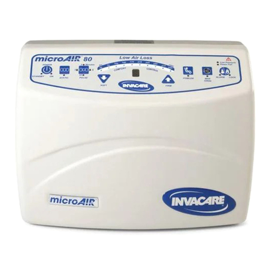
Page 19: Using The Front Panel
4 OPERATION Using the Front Panel DETAIL “A” - MA80 Power Fail LED Low Pressure LED Fowler Button Pulse Button FRONT PANEL Power Button Static Button Lock/Alarm Button Soft Button Max Inflate Button LCD Display Firm Button Low Pressure LED DETAIL “B”... -
Page 20: Power Button
If the power comes on after a power outage, the control unit will go through its system initialization routine for a few seconds and then resume the desired function. Pulse Button (MA80 Power Unit) Press the Pulse button ( ) to turn on Pulse mode and select one of four Pulse Times - 1, 3, 5 or 10 minutes. - Page 21 ) to select the static mode and maintain the mattress at constant pressure. The Static LED is illuminated Green. Part No 1148138 ) and Fowler ( ) buttons. ) buttons to toggle between the two settings. 4 OPERATION Invacare®MA80 Series Mattresses...
- Page 22 Fowler Transmitter Setup Make sure the bed is in the flat position. Make sure fowler transmitter is in the mattress cover pocket in the orientation indicated on the transmitter. Invacare®MA80 Series Mattresses ) or Soft ( ) buttons. Part No 1148138...
- Page 23 It is recommended that Max Inflate setting be used during patient ingress/egress, patient wound care, patient turning or patient cleaning. Press the Max Inflate button again to manually disengage Max Inflate mode. This will deactivate the Max Inflate LED. Part No 1148138 ) buttons. 4 OPERATION Invacare®MA80 Series Mattresses...
-
Page 24: Powering Up The System
Turn on the power to the system by pressing the Power button on the control unit. Once the button is released, a green led illuminates when the unit is on. Invacare®MA80 Series Mattresses ) to select one of the following modes: Part No 1148138... -
Page 25: Placing The Patient On The Mattress
If the patient feels that the bed is too soft/hard, press the Soft or Firm button to adjust the comfort settings. 10. Use a regular pillow to help support and stabilize the patient's head. Part No 1148138 Invacare®MA80 Series Mattresses 4 OPERATION... -
Page 26: Transferring Patient From/To A Gurney
When the mattress has reached maximum firmness, perform one of the following: • Bed to Wheelchair Transfer - Slide the patient onto the wheelchair. • Wheelchair to Bed Transfer - Slide the patient onto the bed. Invacare®MA80 Series Mattresses Part No 1148138... -
Page 27: Preparing For Cpr Procedure
Lift the connector cover (Detail “A”). Pull the hose connector (Detail “B”) from the control unit connector. Control Unit Part No 1148138 DETAIL “A” Connector Cover Control Unit Connector FIGURE 6 Preparing for CPR Procedure 4 OPERATION DETAIL “B” Hose Connector Invacare®MA80 Series Mattresses Holes... -
Page 28: Maintenance And Troubleshooting
Cleaning the System WARNING Before cleaning or disassembling the MA80 series, check the underside of the mattress folds for sharp objects such as scissors, needles, etc. These objects should be removed and discarded before proceeding with further cleaning or disassembly; otherwise injury or damage to the product may occur. - Page 29 Do NOt overload the machine. Do not use chlorine bleach because it may damage the fabric coating. High air temperatures will damage the fabrics and void the Invacare warranty. Place the cover in a washing machine. Wash with warm water (below 120°F).
-
Page 30: Storing The System
Disconnect the air hose connector from the control unit and allow air to vent from the mattress. Gently roll up the mattress with minimal handling and agitation. Ensure the cover surface is inside the roll. Store the unit, keeping the mattress with the control unit. Invacare®MA80 Series Mattresses Part No 1148138... -
Page 31: Changing The Filter
Install the filter into the back of the control unit. Secure the filter cover to the back of the control unit using the two screws. Part No 1148138 5 MAINTENANCE AND TROUBLESHOOTING Filter Cover Screws FIGURE 1 Changing the Filter Invacare®MA80 Series Mattresses... -
Page 32: Troubleshooting
5 MAINTENANCE AND TROUBLESHOOTING Troubleshooting PROBLEM Mattress not inflating Not alternating properly No power Invacare®MA80 Series Mattresses CAUSE Mattress hose disconnected Air hose kinked or split Major leak in the air cushions or overlay Kinked or split manifold Has power and fuse is good, control unit... - Page 33 NOTES NOTES Part No 1148138 Invacare®MA80 Series Mattresses...
- Page 34 NOTES NOTES Invacare®MA80 Series Mattresses Part No 1148138...
- Page 35 NOTES NOTES Part No 1148138 Invacare®MA80 Series Mattresses...
- Page 36 Part No 1148138 Rev D- 1/11 Invacare Corporation Canada One Invacare Way 570 Matheson Blvd E Elyria, Ohio USA Unit 8 44036-2125 Mississauga Ontario 800-333-6900 L4Z 4G4 Canada 800-668-5324 www.invacare.com...
Need help?
Do you have a question about the MicroAir MA80 and is the answer not in the manual?
Questions and answers