
Related Manuals for Invacare 5410VC


Summary of Contents for Invacare 5410VC
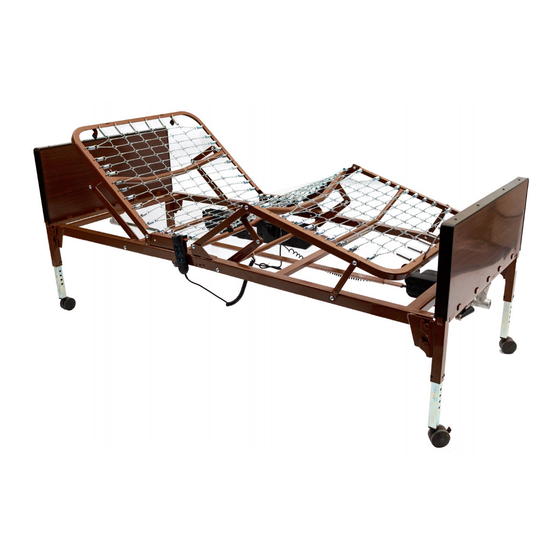
- Page 1 Full-Electric Value Care User Manual & Entrapment Guide For use with Item # ' s 5410VC 5410VCDECK 5410VCHFB...
-
Page 2: Table Of Contents
TABLE OF CONTENTS User Manual ........3 —... -
Page 3: User Manual
WARNINGS PLEASE READ ALL WARNINGS/CAUTIONS BEFORE USE ・ DO NOT use this bed for patient transport. DO NOT move the bed while occupied, otherwise injury or damage may result. ・ DO NOT ・ The maximum safe working load of this bed (patient, mattress, or explosive gases. - Page 4 ・ DO NOT use this bed with incompatible mattresses or bed rails. Refer ・ Keep the product a minimum of 12” away from any direct heat source. to page 17 of this manual or contact your Invacare dealer for Make sure head and foot springs/sections are connected securely to the assistance with purchasing compatible models.
-
Page 5: Special Notes
WARNINGS SPECIAL NOTES NOTICE: perform any work on these beds, the warranty is void. ・ The information contained in this document is subject to change ・ After use, some permanent deformation of the bed under load may without notice. occur. This is normal and expected unless it affects the function of the ・... -
Page 6: Bed Components
BED COMPONENTS. Foot Spring Head Spring Head Board Foot Board Hi/Low Shaft Locking Pins (4) Motor Hand Crank (attached to foot board for shipping) Casters (4) - 2 locking, 2 non-locking Spring Clips (2) Hand Pendant Full Electric Motor... -
Page 7: Assembly Instructions
ASSEMBLY INSTRUCTIONS. NOTE: Spring fabric not shown for clarity ・ Lay the head and foot section on their sides approximately 90° to each other (See Figure 1). l i t ・ catches the rivet on the foot section. ・ ・ Position head wing as shown. , l e ・... - Page 8 ASSEMBLY INSTRUCTIONS . Figure 5 Hanger Figure 4 Spring-loaded Bracket drive shaft Position the foot spring standing upright on its side . ・ Install Hi/Low drive shaft to the Hi/Low motor located on the ・ Slide Hi/Low drive shaft through hanger bracket. foot section.
- Page 9 ASSEMBLY INSTRUCTIONS. Figure 6 With bed on side extend the drive shaft until it reaches the full length of bed. The drive shaft adjustment holes are marked for ・ either semi or full beds. Choose the full bed hole .
- Page 10 ASSEMBLY INSTRUCTIONS. Figure 7 Figure 8 ・ Install the casters by inserting the caster stem into the leg ・ Install the head end of the drive shaft as shown. receptacle. ALWAYS install locking 1 locking and 1 non-locking caster on each bed end. ALWAYS install locking casters diagonally from each other.
- Page 11 ASSEMBLY INSTRUCTIONS. Figure 9 Figure 10 ・ Release the spring-loaded drive shaft on the hi/low motor and ・ Make sure the slot on the spring-loaded drive shaft fully engages insert the drive shaft into the gear box located on the footboard. the roll pin on the motor gear box.
- Page 12 ASSEMBLY INSTRUCTIONS. MOTOR INSTALLATION. Figure 11 Figure 12 ・ For easier set-up, prior to installing the motor, plug both the ・ Connect a 9V battery (not included) to the battery clip located hand pendant and Hi/Low motor cables into motor as shown. on the motor.
- Page 13 SFigure 14 Figure 13 Actuator Rod ・ To install motor, remove both locking caps on top of the motor. ・ Align the motor with the actuator rod and raise the head spring to the highest position. The motor will be pull towards the bed and lock on the actuator rod.
-
Page 14: Hand Pendant Operation
Hand Pendant Operation Battery Operation The full electric bed can be lowered in an emergency when equipped with an installed 9V battery (not included). Battery-powered opera - tion can only be used once and only be used to lower the head and foot sections of the bed. -
Page 15: Head/Footboard Optional Height Adjustment
HEAD/FOOT BOARD MAINTENANCE AND SAFETY CHECKS OPTIONAL HEIGHT ADJUSTMENT technician. Electronics Check all controls to make sure all functions work properly. ・ Power cord ・ Pendant cord ・ Check to make sure all wires are routed and attached properly so they do not interfere with any moving parts. ・... -
Page 16: Bed Schematic
Bed Schematic Headboard Footboard Head spring Foot spring Headboard panel frame Footboard panel frame a. Headboard gear assembly b. Footboard dear assembly Sleep surface hook Motor brackets Hi/Low motor gearbox Caster set (2 locking/2 non-locking) 10. Caster receptacle 11. Frame linkage 12. -
Page 17: Service Life
(9V not included) extend to non-durable components, such as rubber accessories, casters, and grips, which are subject to normal wear and need periodic replacement. ・ If you have questions about your device or this warrant please contact an authorized dealer or Invacare. - Page 18 2020 Hangzhou Dunli Medical Instruments Co.,Ltd No.1 Dunli Road,Renhe Street,Yuhang, Hangzhou,Zhejiang,311107 China DL18-300UM-A 2020-04-13...
Need help?
Do you have a question about the 5410VC and is the answer not in the manual?
Questions and answers