Triton FT5000 Service Manual
Automated teller machine
Hide thumbs
Also See for FT5000:
- User manual (105 pages) ,
- Upgrade manual (24 pages) ,
- Quick reference manual (10 pages)
Table of Contents
Advertisement
Quick Links
RL2000 A
M
S
M
UTOMATED TELLER
ACHINE
ERVICE
ANUAL
FT5000 Automated Teller Machine
Service Manual
07103-00036
5/15/2014
C
H
:
ORPORATE
EADQUARTERS
21405 B Street
Long Beach, MS 39560
Phone: (228) 575-3188
Fax: (228) 575-3101
COPYRIGHT NOTICE
© 2014 Triton. All Rights Reserved. TRITON logo is a registered trademark of Triton Systems of
Delaware, LLC. The third party trademarks that may be identifi ed herein are the trademarks of their
respective owners and are not owned by ATMGurus. ATMGurus disclaims any affi liation, connec-
tion or association between its products and services, and those of the respective trademarks owners,
or any sponsorship or approval of its products or services by such trademarks owners.
Advertisement
Table of Contents

Related Manuals for Triton FT5000


Summary of Contents for Triton FT5000
- Page 1 Fax: (228) 575-3101 COPYRIGHT NOTICE © 2014 Triton. All Rights Reserved. TRITON logo is a registered trademark of Triton Systems of Delaware, LLC. The third party trademarks that may be identifi ed herein are the trademarks of their respective owners and are not owned by ATMGurus. ATMGurus disclaims any affi liation, connec- tion or association between its products and services, and those of the respective trademarks owners, or any sponsorship or approval of its products or services by such trademarks owners.
- Page 2 FT5000 A UTOMATED ELLER ACHINE ERVICE ANUAL [This page intentionally left blank.]...
- Page 3 ABLE OF ONTENTS DISCLAIMER The manufacturer of the Automated Teller Machine product(s) described herein makes no representa- tions or warranties, either expressed or implied, by or with respect to anything in this manual, and shall not be liable for any implied warranties of fi tness for a particular purpose or for any indirect, special or consequential damages.
- Page 4 Repairs and Returns: If telecom compatibility trouble is experienced with the RL2000 Automated Teller Machine, you may contact for repairs and warranty information: Triton at 1-228-575-3100 Triton Systems of Delaware, Inc. 21405 B Street Long Beach, MS 39560 If the equipment is causing harm to the network, the telephone company may request that you discon- nect the equipment until the problem is resolved.
- Page 5 ABLE OF ONTENTS NOTICE: The Ringer Equivalence Number (REN) assigned to each terminal device provides an indication of the maximum number of terminals allowed to be connected to a telephone interface. The termination on an interface may consist of any combination of devices subject only to the requirement that the sum of the Ringer Equivalence Numbers of all the devices does not exceed 5.
- Page 6 FT5000 A UTOMATED ELLER ACHINE ERVICE ANUAL EMISSIONS (EMI) This device complies with Part 15 of the FCC rules. Operation is subject to the following two (2) conditions: 1) This device may not cause harmful interference. 2) This device must accept any interference received, including interference that may cause undesired operation.
- Page 7 All Rights Reserved This publication is protected by copyright and all rights are reserved. No part of it may be reproduced or transmitted by any means or in any form, without prior consent in writing from Triton Systems of Delaware, Inc.
- Page 8 FT5000 A UTOMATED ELLER ACHINE ERVICE ANUAL Warranty Statement Manufacturer warrants that the products delivered to a distributor will perform in accordance with the Manufacturer’s published specifi cations for thirteen months from date of shipment in Long Beach, MS. Manufacturer’s warranty shall not apply to any damage resulting from abuse, negligence or accident, or to any loss or damage to the Products while in transit.
- Page 9 Triton at the purchaser’s expense. Triton shall not be responsible for misuse or abuse of a unit; and any attempts to remove or deface the serial number or date code on a unit or any component thereof, or any attempt to repair a unit or to repair or replace any component by anyone other than a service technician authorized by Triton shall void this warranty.
- Page 10 (including all implied warranties of merchantability or fi tness for a particular purpose or quality of service), are hereby disclaimed. No oral or written information, or advice given by Triton Systems, its agents or employees shall create a warranty or in any way increase the scope of this warranty.
- Page 11 We will credit the purchaser’s account for the full purchase price of the damaged unit, minus the cost of returning the unit to ‘like new” condition. Under no circumstances does Triton au- thorize anyone to complete structural damage repairs in the fi eld. Therefore, we will not ship primary...
- Page 12 By providing the information requested in the voice mail, the technician can be prepared when your call is returned. Triton asks you to be patient if you must leave voice mail, and assures you that your call is important to us and that we will respond...
- Page 13 Technical support is available to owners of Triton equipment and to qualifi ed service personnel. When calling for help with the confi guration or operation of a Triton product, the caller must provide either positive identifi cation as a service technician or the serial number of a Triton terminal. Technical sup- port is provided during normal business hours for the life of the product.
- Page 14 FT5000 A UTOMATED ELLER ACHINE ERVICE ANUAL TABLE OF CONTENTS 1 - I ................25 ECTION NTRODUCTION ’ ? ..............27 ANUAL FT5000 A UTOMATED ELLER ACHINE TANDARD EATURES AND ..................29 PECIFICATIONS ..............30 PERATING PECIFICATIONS 2 - T ..............
- Page 15 ABLE OF ONTENTS : 152 ................45 RROR : 153 ................45 RROR : 154 ................45 RROR : 155 ................45 RROR : 156 ................45 RROR : 157 ................46 RROR : 158 ................46 RROR : 159 ................46 RROR : 160 ................
-
Page 16: Table Of Contents
FT5000 A UTOMATED ELLER ACHINE ERVICE ANUAL : 305(35 )[5] ............55 RROR : 306(36 )[6] ............56 RROR : 307(37 )[7] ............56 RROR : 308(38 )[8] ............56 RROR : 309(39 )[9] ............57 RROR : 310(3A )[:] ............57 RROR : 311 ................ - Page 17 ABLE OF ONTENTS : 367 ................68 RROR : 368 ................68 RROR : 369 ................68 RROR : 370 ................69 RROR : 371 ................69 RROR : 372 ................69 RROR : 373 ................69 RROR : 374 ................69 RROR : 375 ................
- Page 18 FT5000 A UTOMATED ELLER ACHINE ERVICE ANUAL : 520 ................76 RROR : 521 ................77 RROR : 522 ................77 RROR : 523 ................77 RROR : 524 ................77 RROR : 525 ................77 RROR : 526 ................77 RROR : 527 ................
- Page 19 ABLE OF ONTENTS : 567 ................84 RROR : 568 ................84 RROR : 569 ................85 RROR : 570 ................85 RROR : 571 ................85 RROR : 572 ................85 RROR : 573 ................85 RROR : 574 ................86 RROR : 575 ................
- Page 20 : 17 ................98 RROR : 18 ................98 RROR : 48 ................99 RROR : 65 ................99 RROR : 143 ................99 RROR 3 - FT5000 A ECTION UTOMATED ELLER ACHINE ................101 ODULE EPLACEMENT FT5000 A ..... 103...
- Page 21 OURS ABINET NSTALLING LECTRONIC USINESS ................140 OURS ABINET ..142 PENING THE LECTRONIC ATTERY AILED 4 - W FT5000 C ........143 ECTION ORKING ASSETTES ..................145 NTRODUCTION ................145 ASSETTE APACITY ................146 EDIA ONDITION ............146 OCUMENT EFECTS ........
- Page 22 ERVICE ANUAL NMD100 C DJUSTING THE ASSETTE FOR IFFERENT OCUMENT ............153 DJUSTING THE ENGTH ............156 DJUSTING THE IDTH 5 - FT5000 A ECTION UTOMATED ELLER ACHINE ................. 159 REVENTIVE AINTENANCE ..................161 NTRODUCTION ..............161 LEANING THE NCLOSURE ................
- Page 23 ABLE OF ONTENTS Notes...
- Page 24 FT5000 A UTOMATED ELLER ACHINE ERVICE ANUAL...
- Page 25 ECTION NTRODUCTION...
- Page 26 FT5000 A UTOMATED ELLER ACHINE ERVICE ANUAL...
- Page 27 ’ ANUAL 1 - I ECTION NTRODUCTION This section of the manual provides a brief description of the contents of the FT5000 Automated Teller Machine Service Manual. 2 - T ECTION ROUBLESHOOTING This section describes step-by-step fault isolation and repair procedures to assist service personnel in maintaining the cash dispenser.
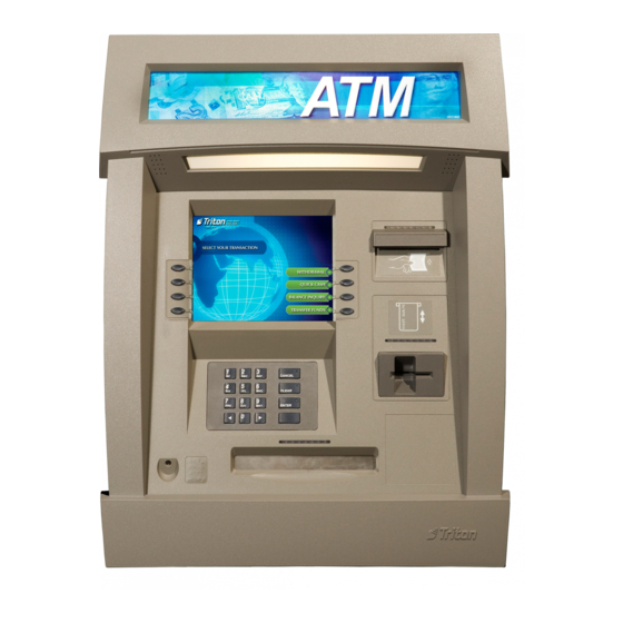
- Page 28 FT5000 A UTOMATED ELLER ACHINE ERVICE ANUAL Figure 1-1. The FT5000 Automated Teller Machime...
- Page 29 1 - I ECTION NTRODUCTIOIN FT5000 A UTOMATED ELLER ACHINE TANDARD EATURES AND PECIFICATIONS • One to four cassettes • 10.4” (264 mm) VGA color display with 640 x 480 resolution • 80 mm thermal paper with presenter • 64 MB RAM standard, 256 MB maximum •...
- Page 30 FT5000 A UTOMATED ELLER ACHINE ERVICE ANUAL Couponing (printed and dispensed) Transaction screen PERATING PECIFICATIONS • Temperature Vault/Electronics 10° - 40° C / 50° - 104° F • Relative Humidity 20% - 80% non-condensing • Power comsumption. 2.0A @ 115 VAC at 60 Hz...
- Page 31 ECTION ROUBLESHOOTING...
- Page 32 FT5000 A UTOMATED ELLER ACHINE ERVICE ANUAL...
- Page 33 2 - T ECTION ROUBLESHOOTING Figure 2-1. FT5000 Automated Teller Machine Block Diagram.
- Page 34 AINTENANCE HILOSOPHY Triton’s philosophy for field repair of the FT5000 Automated Teller Machine (A TM) is a to determine the faulty module and replace it. This section of the manual reflects the modular repair approach in that it will assist you to quickly locate a defective module and direct you to the simplest method of replacing it.
- Page 35 2 - T ECTION ROUBLESHOOTING IRST HECKS When the ATM is not working, the first thing to check its external environment. Make sure that working dedicated AC power source and a working dedicated tele- phone line are available and connected to the ATM. Make sure the main power circuit breakers are ON.
- Page 36 Inspect the printer mechanism for the following: Platen is in the open position. Verify that the blue leaver is in Figure 2-3. FT5000 Printer Controller the print position. This condi- Board Dip Switch Settings tion results in Error/S tatus Code 139.
- Page 37 Turn on the digital multimeter. Set the meter to measure DC voltage. Set the meter range to a value higher than the voltage that will be measured. If the meter has a range switch set it to measure at least +36 VDC. Figure 2-5. Voltage outputs from the FT5000 power supply.
- Page 38 EFECTIVE USES There are two fuses in the FT5000 Automated Teller Machine power supply. The first is a 6.3 AMP 250 VOLT fuse used to protect all devices that are connected to the AC outputs of the power supply . This fuse is located at the bottom of the black AC power distribution block located on the left side of the power supply near the AC power ON/OFF switch (Refer to Figure 3-9).
- Page 39 Y THE ERIES The following paragraphs provide a list of the error codes associated with the FT5000 Series ATM. The information provides the error (decimal and hexadecimal) code numbers, the error definitions and some recommended actions that may be taken to correct the cause of a “out of service”...
-
Page 40: Error Code : 305(35 H )[5]
FT5000 A UTOMATED ELLER ACHINE ERVICE ANUAL : 129 RROR : No response from the dispenser mechanism. ESCRIPTION ECOMMENDED CTION See the recommended action for error code 128. : 130 RROR : Command not acknowledged by the dispenser mechanism. ESCRIPTION... - Page 41 2 - T ECTION ROUBLESHOOTING : 134 RROR : Exit blocked as reported by error code check. ESCRIPTION ECOMMENDED CTION Inspect the feed path exit sensor for jammed documents and broken compo- nents. The exit sensor may be dirty . Clean as needed with compressed air . Reset the cash dispenser by turning OFF the AC power switch for a few sec- onds and switching it back ON.
- Page 42 FT5000 A UTOMATED ELLER ACHINE ERVICE ANUAL printer and verify that there are no jams in the printer or the paper path. Verify the blue lever on the left side of the printer in the print position. Inspect the cable supplying DC power from the power supply to the printer. Make sure it is connected to CN1 on the printer control board.
- Page 43 2 - T ECTION ROUBLESHOOTING : 142 RROR : Dispenser returns bad command error. ESCRIPTION ECOMMENDED CTION See the recommended action for error code 128. : 143 RROR : PTDF error. ESCRIPTION ECOMMENDED CTION This error code will occur only in cash dispensers running ACS terminal soft- ware.
- Page 44 FT5000 A UTOMATED ELLER ACHINE ERVICE ANUAL : 147 RROR : Error in reply from electronic journal. ESCRIPTION ECOMMENDED CTION See the recommended action for error code 144. : 148 RROR : Write to electronic journal failed. ESCRIPTION ECOMMENDED CTION See the recommended action for error code 144.
- Page 45 2 - T ECTION ROUBLESHOOTING : 152 RROR : Electronic journal corrupt. ESCRIPTION ECOMMENDED CTION See the recommended action for error code 144. : 153 RROR : Electronic journal mode. ESCRIPTION ECOMMENDED CTION See the recommended action for error code 144. : 154 RROR : Unknown electronic journal...
- Page 46 FT5000 A UTOMATED ELLER ACHINE ERVICE ANUAL : 157 RROR : Format command to electronic journal failed. ESCRIPTION ECOMMENDED CTION See the recommended action for error code 144. : 158 RROR : Format command to electronic journal failed. ESCRIPTION ECOMMENDED CTION See the recommended action for error code 144.
- Page 47 ECOMMENDED CTION This error is not displayed at the cash dispenser . The Triton Connect Host Computer generates the error when a terminal does not respond to a telephone call from the Triton Connect Host Computer . The cash dispenser may be turned OFF, or the telephone line is shared with some other device that connects to the line before the cash dispenser .
- Page 48 ECOMMENDED CTION This is a message to the Triton Connect Host indicating that the last in serviceCassette has reach at the Low Cash Threshold level. This is a warning message that will not place the ATM “Out of Service”. The ATM should be...
- Page 49 2 - T ECTION ROUBLESHOOTING : 187 RROR : Maximum withdrawal not configured. ESCRIPTION ECOMMENDED CTION Enter management functions and configure the maximum amount. The maxi- mum withdrawal cannot exceed 50 time the denomination of the of the of the bill size in the cassette.
- Page 50 FT5000 A UTOMATED ELLER ACHINE ERVICE ANUAL : 193 RROR : The baud rate setting for electronic journal failed. ESCRIPTION ECOMMENDED CTION Inspect the electronic journal to make sure is it the correct part number . Reset the cash dispenser and clear the error . If the error persists, replace the Elec- tronic Journal.
- Page 51 2 - T ECTION ROUBLESHOOTING : 203 RROR : SPED keypad is not replying to main board. ESCRIPTION ECOMMENDED CTION valid only for units with SPED keypad device installed. Make RROR CODE sure the battery is seated secure in the battery holder . Make sure the tamper screw is secure to the SPED module.
- Page 52 FT5000 A UTOMATED ELLER ACHINE ERVICE ANUAL : 207 RROR : SPED not detected. ESCRIPTION : This E is valid for units with SPED keypad ECOMMENDED CTION RROR device installed. Check the cable and connections from the docking station to the SPED board.
- Page 53 2 - T ECTION ROUBLESHOOTING : 231 RROR : Warning: Card left in card reader. ESCRIPTION ECOMMENDED CTION Inspect the card reader for any foreign debris that is jammed in card slot. Re- move any foreign objects. Replace the card reader. : 233 RROR : Smart card reader not installed.
- Page 54 FT5000 A UTOMATED ELLER ACHINE ERVICE ANUAL : 300(30h)[0] RROR : Successful Command ESCRIPTION ECOMMENDED CTION The dispenser sends this when a command has been successfully ERROR CODE executed. This error code will appear in the electronic journal as code 300 indicating the successful completion of a transaction.
- Page 55 2 - T ECTION ROUBLESHOOTING be placed “Out of Service” when all cassettes are empty . Remove and refill the affected cassette using normal replenishment procedures. : 303(33h)[3] RROR : Lifts are down. ESCRIPTION ECOMMENDED CTION This error code is generated when a cassette is not open and any command other than open cassettes, reset, and close cassettes are sent to the system.
- Page 56 FT5000 A UTOMATED ELLER ACHINE ERVICE ANUAL note diverter moves the currency to the exit position. If the error reoccurs the most likely causes of the problem may be note transport or CMC. : 306(36h)[6] RROR Descriptionm: Failure to feed.
-
Page 57: Error Code : 310(3Ah)[:]
2 - T ECTION ROUBLESHOOTING : 309(39h)[9] RROR : Jam in Note Qualifier. ESCRIPTION ECOMMENDED CTION This error code is generated when the note transport sensor does not detect a note that was detected by the note qualifier . This may be due to jammed docu- ments in the transport path between the note qualifier and the note diverter . -
Page 58: Error Code : 311
FT5000 A UTOMATED ELLER ACHINE ERVICE ANUAL : 311 RROR : Configuration record size invalid ESCRIPTION ECOMMENDED CTION To be determined. : 312(3Ch)[?] RROR : No notes retracted ESCRIPTION ECOMMENDED CTION This is a warning message. No action is required. -
Page 59: Error Code : 316(40H)[?]
2 - T ECTION ROUBLESHOOTING : 316(40h)[?] RROR : Delivery Failure ESCRIPTION ECOMMENDED CTION Reset the ATM. If the error persists, it may be necessary to use the diagnostics progam to determine the status of the count sensors. Clean dirty sensors. It may be necessary to replace the dispenser : 317(41h)[A] RROR... -
Page 60: Error Code : 320(44H)[D]
The error code will be sent to the Triton Connect host if Triton Connect feature is enabled. It will also be stored as part of the transaction data in the electronic journal. The reject vault should be emptied as soon as possible in order to avoid an “Out of Service”... -
Page 61: Error Code : 325(49H)[I]
2 - T ECTION ROUBLESHOOTING plete several test dispenses. If cash dispenser operates normally when per forming the test dispense function, put the cash dispenser in service. It the error code repeats, verify the power supply output voltages are within expected values. -
Page 62: Error Code : 327(4Bh)[K]
Inspect all cables for damage. Verify that the both ends of each cable are securely connected to its termination points. This problem may be caused by incompatibilities between terminal software and dispensing mecha- nism software. Check with Triton Systems Technical Support for known soft- ware incompatibilities. -
Page 63: Error Code : 332(50H)[P]
2 - T ECTION ROUBLESHOOTING : 332(50h)[P] RROR : Cassettes may have been changed. ESCRIPTION ECOMMENDED CTION This error code is generated when a movement command is sent before read cassette ID command after the cassettes, including the reject vault are removed. This is error code will set an “Out of Service”... -
Page 64: Error Code : 343(5Bh)[[]
FT5000 A UTOMATED ELLER ACHINE ERVICE ANUAL : 343(5Bh)[[] RROR : Sensor error or sensor covered. ESCRIPTION ECOMMENDED CTION This error is produced when a sensor in note transport module is not working correctly during an internal self-test preceding the movement commands. In- spect all cables for damage. -
Page 65: Error Code : 350(62H)[B]
2 - T ECTION ROUBLESHOOTING : 350(62h)[b] RROR : Error in note stacker area. ESCRIPTION ECOMMENDED CTION Turn off the ATM. Open the security cabinet and clear any jammed notes found in the dispenser. Make sure all access panels are securely closed. Inspect for misaligned or damaged modules. -
Page 66: Error Code : 356(68)[H]
FT5000 A UTOMATED ELLER ACHINE ERVICE ANUAL : 356(68)[h] RROR : Error in note transport. ESCRIPTION ECOMMENDED CTION This error code will be generated when the following conditions occur: 1. When the note is stuck in the note transport sensor . 2. When the note is stuck in between the note transport sensor and the throat. - Page 67 2 - T ECTION ROUBLESHOOTING : 360 RROR : Dispenser invalid return ID. ESCRIPTION ECOMMENDED CTION Restart the operating system. Clear terminal error code. Replace the dispenser is the error persists. : 361 RROR : Dispenser sequence error. ESCRIPTION ECOMMENDED CTION Restart the operating system.
-
Page 68: Error Code : 360
FT5000 A UTOMATED ELLER ACHINE ERVICE ANUAL : 365 RROR : Dispenser BCC error. ESCRIPTION ECOMMENDED CTION Restart the operating system. Clear terminal error code. Replace the dispenser is the error persists. : 366 RROR : Dispenser cassettes disabled. ESCRIPTION... -
Page 69: Error Code : 365
2 - T ECTION ROUBLESHOOTING : 370 RROR : Dispenser - SDD EOT error. ESCRIPTION ECOMMENDED CTION Check data and power connections to the dispenser device. Clear terminal error code. If error persists, replace the dispenser mechanism. : 371 RROR : Dispenser SDD com error header-trailer. - Page 70 FT5000 A UTOMATED ELLER ACHINE ERVICE ANUAL : 375 RROR : Dispenser invalid request. ESCRIPTION ECOMMENDED CTION Clear terminal error code. If error persists, replace the dispenser mechanism. : 376 RROR : Dispenser multiple device error. ESCRIPTION ECOMMENDED CTION Restart operating system. Clear terminal error code. If error persists, replace the dispenser mechanism.
- Page 71 2 - T ECTION ROUBLESHOOTING : 383 RROR : Dispense cassettes low (ALL). ESCRIPTION ECOMMENDED CTION All cassettes have reached low cash level. Reload cassettes. Clear terminal error code. : 384 RROR : Dispenser cassettes empty (ALL). ESCRIPTION ECOMMENDED CTION All cassettes report no notes.
- Page 72 ECOMMENDED CTION Restart the operating system. Verify the error code lights on the dispenser are operating in proper sequence. Use the NMD test software (available to Triton Certified Service Technicians) and verify the operational error code of the dis- penser.
- Page 73 2 - T ECTION ROUBLESHOOTING : 392 RROR : Error in last dispense. ESCRIPTION ECOMMENDED CTION Check operational of dispenser. Replace dispenser if error code ERROR CODE persists. : 395 RROR : Multiple cassette of the same type. ESCRIPTION ECOMMENDED CTION NMD dispenser allows for only one of each cassette ID to be installed.
- Page 74 FT5000 A UTOMATED ELLER ACHINE ERVICE ANUAL : 503 RROR : SPED invalid command. ESCRIPTION ECOMMENDED CTION Refer to error 500. : 504 RROR : SPED invalid return ID. ESCRIPTION ECOMMENDED CTION Refer to error 500. : 505 RROR : SPED device busy.
- Page 75 2 - T ECTION ROUBLESHOOTING : 509 RROR : SPED no data. ESCRIPTION ECOMMENDED CTION Refer to error 500. : 510 RROR : SPED invalid message ID. ESCRIPTION ECOMMENDED CTION Refer to error 500. : 511 RROR : SPED Data overflow. ESCRIPTION ECOMMENDED CTION...
- Page 76 FT5000 A UTOMATED ELLER ACHINE ERVICE ANUAL : 515 RROR : SPED device attention stuck. ESCRIPTION ECOMMENDED CTION Refer to error 500. : 516 RROR : SPED device no attention. ESCRIPTION ECOMMENDED CTION Refer to error 500. : 517 RROR : SPED device timeout.
- Page 77 2 - T ECTION ROUBLESHOOTING : 521 RROR : SPED clear key ESCRIPTION ECOMMENDED CTION Refer to error 500. : 522 RROR : EJ error. ESCRIPTION ECOMMENDED CTION Inspect electronic journal cabling. Reseat connections. Restart operating sys- tem. Replace electronic journal. : 523 RROR : EJ data size error.
- Page 78 FT5000 A UTOMATED ELLER ACHINE ERVICE ANUAL : 527 RROR : EJ invalid request. ESCRIPTION : Refer to error 522. ECOMMENDED CTION : 528 RROR : EJ sequence error. ESCRIPTION ECOMMENDED CTION Refer to error 522. : 529 RROR : EJ device of fline.
- Page 79 2 - T ECTION ROUBLESHOOTING : EJ BCC error. ESCRIPTION ECOMMENDED CTION Refer to error 522. : 534 RROR : EJ device reset. ESCRIPTION ECOMMENDED CTION Refer to error 522. : 535 RROR : Card Reader - Data size error. ESCRIPTION ECOMMENDED CTION...
- Page 80 FT5000 A UTOMATED ELLER ACHINE ERVICE ANUAL : 539 RROR : Card Reader - Invalid track. ESCRIPTION ECOMMENDED CTION Refer to error code 535. : 540 RROR : Card Reader - Invalid message. ESCRIPTION ECOMMENDED CTION Refer to error code 535.
- Page 81 2 - T ECTION ROUBLESHOOTING : 545 RROR : Card Reader - LRC error. ESCRIPTION ECOMMENDED CTION Refer to error code 535. : 546 RROR : Card Reader - No data. ESCRIPTION ECOMMENDED CTION Refer to error code 535. : 547 RROR : Card Reader - Start sentinel not found.
- Page 82 FT5000 A UTOMATED ELLER ACHINE ERVICE ANUAL : 551 RROR : Card Reader - Card removed to slow. ESCRIPTION ECOMMENDED CTION Refer to error code 535. : 552 RROR : Card Reader - Device received invalid request. ESCRIPTION ECOMMENDED CTION Refer to error code 535.
- Page 83 2 - T ECTION ROUBLESHOOTING : 557 RROR : System device reset. ESCRIPTION ECOMMENDED CTION Verify operation of the power supply. Restart ATM. Clear the error. If error persists, replace the main board assembly. : 558 RROR : System sync error. ESCRIPTION ECOMMENDED CTION...
- Page 84 FT5000 A UTOMATED ELLER ACHINE ERVICE ANUAL : 562 RROR : SPED error. ESCRIPTION ECOMMENDED CTION Inspect cable from Main Board assembly to the SPED module for damage. Make sure that cable is connected at both ends. Verify that the DC operating voltages are correct.
- Page 85 2 - T ECTION ROUBLESHOOTING : 569 RROR : Security module attached dev com failed. ESCRIPTION ECOMMENDED CTION See error code 567. : 570 RROR : Security module dev port setup. ESCRIPTION ECOMMENDED CTION See error code 567. : 571 RROR : Invalid default transaction.
- Page 86 FT5000 A UTOMATED ELLER ACHINE ERVICE ANUAL : 574 RROR : SNA comms error. ESCRIPTION ECOMMENDED CTION To be determined. : 575 RROR : Timeout waiting to send command to dispenser. ESCRIPTION ECOMMENDED CTION Inspect the serial communication cables from the main board assembly to the electronic journal and from the electronic journal to the dispenser for damage.
- Page 87 2 - T ECTION ROUBLESHOOTING : 578 RROR : Card reader present timeout. ESCRIPTION ECOMMENDED CTION Inspect card reader cable. Inspect the card reader for foreign objects. Replace the cable or clean the card reader as needed. Clear the error . Restart the ATM. If the error persists, replace the card reader.
- Page 88 FT5000 A UTOMATED ELLER ACHINE ERVICE ANUAL : 582 RROR : SPED - Disable key from pad module. ESCRIPTION ECOMMENDED CTION Inspect cable from main board assembly to the SPED module for damage. Make sure that the cable is connected at both ends.
- Page 89 2 - T ECTION ROUBLESHOOTING : 586 RROR : SPED - Enable JETCO PIN entry mode failed. ESCRIPTION ECOMMENDED CTION Inspect cable from main board assembly to the SPED module for damage. Make sure that the cable is connected at both ends. Verify that the DC operating voltages are correct.
- Page 90 FT5000 A UTOMATED ELLER ACHINE ERVICE ANUAL : 589 RROR : ERR_PRESENTER_MOT OR_STALLED ESCRIPTION ECOMMENDED CTION Inspect the gears assembly on the presenter for possible damage. Replace the pre- senter if gear damage is apparent. Open printer and inspect the presenter paper path for jammed paper.
- Page 91 2 - T ECTION ROUBLESHOOTING voltages are correct. Restart ATM. Clear the error. If error persists, replace the SPED module. : 594 RROR : ERR_SPED_DEVICE _REPOR TED_COMM_ERROR ESCRIPTION ECOMMENDED CTION Inspect cable from main board assembly to the SPED module for damage. Make sure that the cable is connected at both ends.
- Page 92 FT5000 A UTOMATED ELLER ACHINE ERVICE ANUAL : 598 RROR : ERR_SPED_INVALID_DEVICE_CLASS ESCRIPTION ECOMMENDED CTION Inspect cable from main board assembly to the SPED module for damage. Make sure that the cable is connected at both ends. Verify that the DC operating voltages are correct.
- Page 93 2 - T ECTION ROUBLESHOOTING voltages are correct. Restart ATM. Clear the error. If error persists, replace the SPED module. : 603 RROR : ERR_SPED_REPORTED_TAMPER_PRESENT ESCRIPTION ECOMMENDED CTION Inspect cable from main board assembly to the SPED module for damage. Make sure that the cable is connected at both ends.
- Page 94 FT5000 A UTOMATED ELLER ACHINE ERVICE ANUAL : 607 RROR : ERR_SPED_REPORTED_PIN_RETRY_TOO_SOON ESCRIPTION ECOMMENDED CTION Inspect cable from main board assembly to the SPED module for damage. Make sure that the cable is connected at both ends. Verify that the DC operating voltages are correct.
- Page 95 2 - T ECTION ROUBLESHOOTING sure that the cable is connected at both ends. Verify that the DC operating voltages are correct. Restart ATM. Clear the error. If error persists, replace the SPED module. : 612 RROR : ERR_SPED_TAMPER_STATUS_COLD ESCRIPTION ECOMMENDED CTION Inspect cable from main board assembly to the SPED module for damage.
- Page 96 FT5000 A UTOMATED ELLER ACHINE ERVICE ANUAL : 616 RROR : ERR_SPED_TAMPER_STATUS_VOLTAGE ESCRIPTION ECOMMENDED CTION Inspect cable from main board assembly to the SPED module for damage. Make sure that the cable is connected at both ends. Verify that the DC operating voltages are correct.
- Page 97 2 - T ECTION ROUBLESHOOTING RROR : BCD NOANSWER ESCRIPTION OSSIBLE AUSE Possible may be a processor or telephone hardware problem. ESULTS No money is dispensed, screen and receipt display system unavailable RROR : ERROR IN MODEM DATA ESCRIPTION OSSIBLE AUSE Unexpected data received from processor in response to message.
- Page 98 FT5000 A UTOMATED ELLER ACHINE ERVICE ANUAL : No connect ESCRIPTION OSSIBLE AUSE Used up all radial attempt and got Busy Signal for each attempt or No Dial Tone for each attempt. Got connected and never received ENQ within time-out period (14 Seconds).
- Page 99 2 - T ECTION ROUBLESHOOTING : 18 RROR : OVERFLOW ESCRIPTION OSSIBLE AUSE Received more characters, than expected after request causing modem buf fer over- flow. ESULTS No money is dispensed, screen and receipt display system unavailable. : 48 RROR : NO ANSWER ESCRIPTION OSSIBLE...
- Page 100 FT5000 A UTOMATED ELLER ACHINE ERVICE ANUAL...
- Page 101 ECTION FT5000 A UTOMATED ELLER ACHINE ODULE EPLACEMENT...
- Page 102 FT5000 A UTOMATED ELLER ACHINE ERVICE ANUAL...
- Page 103 EPLACEMENT FT5000 AUTOMATED TELLER MACHINE MODULE DESCRIPTION The function of the each major components that comprise the FT5000 Automated Teller Machine is described in the following paragraphs. Photographs showing the location of each module can be found in Figure 3-1 through Figure 3-6.
- Page 104 It also keep track of cash dispenser error condi- tions. The electronic journal in the FT5000 Automated Teller Machine is capable of storing up to 32,768 separate records on the main board assembly . These records can be viewed on the LCD screen, printed to the receipt printer , or saved to an external device such as a USB pin drive.
- Page 105 3 - FT5000 A ECTION UTOMATED ELLER ACHINE ODULE EPLACEMENT but can be configured to read tracks 2 and 3. An optional smart card reader is available. 09200-00010) OLOR NVERTER SSEMBLIES UMBER The color LCD is used for presenting visual information to the end user . It will displaying 256 color graphics that have a maximum resolution of 340 X 240 pixels.
- Page 106 FT5000 A UTOMATED ELLER ACHINE ERVICE ANUAL Rear Control Panel Back lit sign Screen keypads Lead thru 10.4 inch LCD display Receipt printer chute Audio Jack Lead thru Card reader Main keypad Lead thru Shutter Security cabinet Figure 3-1. FT500 Automated Teller Machine front view.
- Page 107 Panel Display Rear Control Rear Control Panel Printer Panel Keypad Chute Cabinet Sleeve Door Lock and door Cooling Cabinet Sleeve Electronic Combination lock Security Security Cabinet Cabinet Door Latch Security Cabinet Door Figure 3-2. FT5000 Automated Teller Machine rear view.
- Page 108 ANUAL Security Module (Hidden) Electronic Combination Lock Battery Dispensing Mechanism and Cassettes Figure 3-3. FT5000 Automated Teller Machine rear view with security cabinet door open. Figure 3-4. FT5000 Automated Teller Machine with cash dispensing mechanism fully extended from the cabinet.
- Page 109 3 - FT5000 A ECTION UTOMATED ELLER ACHINE ODULE EPLACEMENT Power supply and DC power Cooling fan distribution assemblies Figure 3-5. The components located on the inside of the FT5000 Automated Teller Machine cabinet sleeve door.
- Page 110 Printer, Cutter and Printer Receipt Transport Assembly (Hidden behind paper Display Assembly Speakers roll). Printer Controller Assembly Printer Paper Main Roll Board Assembly Modem Assembly Card Assembly Reader Power Supply Figure 3-6. FT5000 Control Panel rear view. Major component location.
- Page 111 3 - FT5000 A ECTION UTOMATED ELLER ACHINE ODULE EPLACEMENT EPLACING ODULES EPLACING OWER UPPLY The function of the power supply is to provide all of the necessary operating volt- ages for the other components in the cash dispenser. The output voltages are 115 VAC for auxiliary AC power, and +5 VDC, +12 VDC, +24 VDC or +36 VDC.
- Page 112 EFECTIVE USES There are two fuses in the FT5000 Automated Teller Machine power supply. The first is a 6.3 AMP 250 VOLT fuse used to protect all devices that are connected to the AC outputs of the power supply . This fuse is located at the bottom of the black AC power distribution block located on the left side of the power supply near the AC power ON/OFF switch (See Figure 3-9).
- Page 113 3 - FT5000 A ECTION UTOMATED ELLER ACHINE ODULE EPLACEMENT 5 AMP 250 VOLT Fuse Figure 3-10. Remove the power supply from the cabinet to ac- cess the 5.0 AMP 250 VOLT fuse. EPLACING THE OARD SSEMBLY Refer to Figures 3-6. The main board assembly is located on the control panel.
- Page 114 Locking Pin FT5000 A UTOMATED ELLER ACHINE ERVICE ANUAL to the LCD display assembly. Refer to Figure 3-12. Lift the locking pin that secures the main board to it mounting bracket. Grasp the main board assembly by its case and carefully pull it away from the connector on the docking assembly.
- Page 115 3 - FT5000 A ECTION UTOMATED ELLER ACHINE ODULE EPLACEMENT the display assembly. Connect the telephone line adapter connector to the modem assembly. Connect AC power to the cash dispenser by plugging it into the AC wall outlet. Push the AC power ON/OFF switch to the ON(1) position.
- Page 116 FT5000 A UTOMATED ELLER ACHINE ERVICE ANUAL connector from the modem as- sembly. Refer to Figure 3-15. Push the PCMCIA card eject button to eject the modem from the slot. Remove the modem from the PCMCIA slot. NSTALLING THE ODEM Figure 3-15.
- Page 117 3 - FT5000 A ECTION UTOMATED ELLER ACHINE ODULE EPLACEMENT 1 - #2 Phillips screwdriver To remove the display assembly the proceed as follow: Unlock and open the cabinet sleeve door. Turn off the AC input power by pushing the AC ON/OFF switch to the OFF(0) position..
- Page 118 FT5000 A UTOMATED ELLER ACHINE ERVICE ANUAL Disconnect all connectors on the printer control board and presenter control board. Remove the printer and presenter assemblies from the control panel. Carefully cut all tie wraps from the cable harness that passes below the display assembly.
- Page 119 3 - FT5000 A ECTION UTOMATED ELLER ACHINE ODULE EPLACEMENT EPLACING RINTER ONTROL OARD The printer control board is located in the printer assembly . . It is a field replaceable module. EMOVING THE RINTER ONTROL OARD OOLS 1 - ESD wrist strap with grounding cord...
- Page 120 FT5000 A UTOMATED ELLER ACHINE ERVICE ANUAL Secure the printer control board to the printer assembly with the four screws that were removed earlier. Verify that the dip switches on the printer control board conform with the switch setting shown in Figure 3-20.
- Page 121 3 - FT5000 A ECTION UTOMATED ELLER ACHINE ODULE EPLACEMENT EPLACING THE RINTER UTTER SSEMBLY The printer/cutter is located on the printer assembly. The printer and cutter can be separated from each other so they can be replaced as separate modules.
- Page 122 FT5000 A UTOMATED ELLER ACHINE ERVICE ANUAL mounting assembly side plate. Split Ring Grommet Remove the wires from the grommet. Close and lock the printer in its operating position. Remove the three screws shown in Figure 3- Pull on the printer locking pin and pull the bottom of the printer Figure 3-23.
- Page 123 3 - FT5000 A ECTION UTOMATED ELLER ACHINE ODULE EPLACEMENT Replace the cable ties the were removed earlier. Connect all of the cables from the printer/cutter to the printer control board. Inspect all work prior to applying power the cash dispenser.
- Page 124 FT5000 A UTOMATED ELLER ACHINE ERVICE ANUAL port bracket to the bottom of the printer assembly. Remove the printer/presenter assembly from the control panel by gently pressing down on the printer support bracket while carefully rotating the part of the printer/presenter that was attached to the control panel up until it clears the control panel.
- Page 125 Disconnect the telephone line adapter connector from the mo- dem assembly. Remove the main board assem- Figure 3-28. The FT5000 docking assembly. bly. Refer to Figure 3-29. Carefully unplug all connectors from the docking assembly. Refer to Figure 3-28. Remove the screw in the center of the PCB (This screw is highlighted by the circle in Figure 3-28.) Assembly.
- Page 126 FT5000 A UTOMATED ELLER ACHINE ERVICE ANUAL DC power input 1 - Ethernet 2- USB master ports To lead-through LEDs To audio board To the card reader To the dispenser To the SPED board To main board assembly Printer communication...
- Page 127 3 - FT5000 A ECTION UTOMATED ELLER ACHINE ODULE EPLACEMENT NSTALLING THE OCKING OARD Align docking assembly with the four mounting devices. Push down on the PCB assembly to seat it on the mounting pins. Put on the ESD wrist strap and attach the clip on the cord to ground.
- Page 128 3 Ft5000 A ection utomAted eller AchineS odule eplAcement emoving the ScAle ocking oArd The Rev B docking board is significantly different from the origi- nal configuration. Note that there is no "Power Present" LED, J26 is no longer the LCD "position" jumper, and that the board layout is changed.
- Page 129 Ft5000 A utomAted eller Achine ervice AnuAl J3 1 - Ethernet 2 - USB master ports J7 - VGA Color J9 - LCD inverter power J11 - Display J16 - To mainboard J14 - To Printer and Low Paper To EPP...
- Page 130 FT5000 A UTOMATED ELLER ACHINE ERVICE ANUAL EPLACING EADER Hidden behind the card reader The card reader is attached to the con- trol panel. To replace the card reader proceed as follows: EMOVING THE EADER Unlock and open the top enclo- sure.
- Page 131 3 - FT5000 A ECTION UTOMATED ELLER ACHINE ODULE EPLACEMENT EPLACING THE UDIO SSEMBLY The audio board provides the interface to connect a headset to the cash dis- penser. The audio board will not be installed in units sold outside the conti- nental U.S.
- Page 132 FT5000 A UTOMATED ELLER ACHINE ERVICE ANUAL EPLACING CREEN EYPAD There are two 1X4 Keypads in the cash dispenser . These keypads make up the screen keys located adjacent to each side of the display on the control panel. Figure 3-32, The screen keypad PCBs.
- Page 133 EPLACING SSEMBLY The SPED (EPP) assembly is located on the control panel. The SPED assembly is a non repairable module. It must be returned to Triton if the battery or the keys need replacement. *NOTE* Removing the EPP module from the control panel no longer cause loss of encryption keys.
- Page 134 FT5000 A UTOMATED ELLER ACHINE ERVICE ANUAL the six screws that secure the SPED assembly to the control panel. Remove the SPED assembly from the control panel. SPED A NSTALLING THE SSEMBLY Put on the ESD wrist strap and attach the clip on the cord to ground.
- Page 135 3 - FT5000 A ECTION UTOMATED ELLER ACHINE ODULE EPLACEMENT EMOVING THE ECURITY ODULE Unlock and open the cabinet sleeve door. Turn off the AC input power by pushing the AC ON/OFF switch to the OFF(0) position. Put on the ESD wrist strap and attach the clip on the cord to ground.
- Page 136 5. Remove the cassettes and reject vault from the dispensing mechanism Figure 3-35. The location of the locking pin on the left slide rail. Figure 3-36. FT5000 dispenser extended with reject vault and cassettes removed Refer Figures 3-35 and 3-36. Pull the dispensing mechanism out of the cabinet until it reaches it’s fully extended position.
- Page 137 3 - FT5000 A ECTION UTOMATED ELLER ACHINE ODULE EPLACEMENT **WARNING** Two people are recommended to remove the dispenser from the cabinet. When removing dispenser from cabi- net, use caution not to damage the throat extension on front of dispenser mechanism. Additionally each person handling the mechanism should be wearing an ESD wrist strap with the clip attach to ground.
- Page 138 FT5000 A UTOMATED ELLER ACHINE ERVICE ANUAL Slot Figure 3-40. Tab and slot aligned for dispenser installation on rails **WARNING** Two people are recommended to install the dispenser into the cabinet. When installing dispenser into cabinet, use caution not to damage the throat extension on front of dispenser mechanism.
- Page 139 3 - FT5000 A ECTION UTOMATED ELLER ACHINE ODULE EPLACEMENT sure proper installation. 4. Connect the A/C power cable to the dispenser power supply . See Figure 3-38. 5. Push the dispenser into the cabinet until the slide rail locking pin is engaged.
- Page 140 FT5000 A UTOMATED ELLER ACHINE ERVICE ANUAL Figure 3-44. Loosen the two screws (highlighted in white circles) that secure the shutter assembly face plate to the control panel. Refer to Figure 3-44. Loosen the two screws that secure the tabs that hold the shutter assembly face plate to the control panel.
- Page 141 3 - FT5000 A ECTION UTOMATED ELLER ACHINE ODULE EPLACEMENT Figure 3-46. Loosen the four screws (highlighted in white circles) that hold the shutter assembly to the control panel. assembly to the control panel with the four screws that were removed during the removal procedure.
- Page 142 FT5000 A UTOMATED ELLER ACHINE ERVICE ANUAL EPLACING LECTRONIC OMBINATION IN USINESS OURS ABINET This procedure is applicable only when the security cabinet door is open. If the is combination lock faulty or the combi- nation has be misplaced, the lock will have to be drilled to open the door .
- Page 143 3 - FT5000 A ECTION UTOMATED ELLER ACHINE ODULE EPLACEMENT If a new brass spindle is select a the one from the Lock Replacement Kit that is same length as the brass spindle that was removed from the original lock.
- Page 144 FT5000 A UTOMATED ELLER ACHINE ERVICE ANUAL PENING THE LECTRONIC ATTERY AILED Repeated beeping while the lock is open indicates that the 9 volt battery , located in the battery box on the inside of the cabinet needs to be replaced.
- Page 145 ECTION FT5000 C ORKING ASSETTES...
- Page 146 FT5000 A UTOMATED ELLER ACHINE ERVICE ANUAL...
- Page 147 ASSETTE APACITY The FT5000 Automated Teller Ma- chine (ATM) uses the NMD-100 dis- pensing mechanism. The NMD-100 is configured with from one to four cas- settes with a single reject vault. Cur - rency capacity for an individual cassette is approximately 3000 documents.
- Page 148 FT5000 A UTOMATED ELLER ACHINE ERVICE ANUAL EDIA ONDITION If possible, store the documents at room temperature for at least eight hours before dispensing from the cassettes. The number of rejects can be directly influenced by the technique used to load the cassettes, the quality of the documents, and how many documents are put into the cassette.
- Page 149 4 - W FT5000 C ECTION ORKING WTTH ASSETTES Preparing Notes Use the following procedures to pre- pare documents before inserting them into the cassette. Do not reuse rejected documents. Refer to Figure 4-2. Prepare used docu- ments using any or all of the following techniques: Figure 4-3.
- Page 150 FT5000 A UTOMATED ELLER ACHINE ERVICE ANUAL Continue to support the bottom of the cassette to keep it level as you place it on a table or other flat sur - face. NSTALLING ASSETTES Once the cassettes have been loaded...
- Page 151 4 - W FT5000 C ECTION ORKING WTTH ASSETTES in Figure 4-7. Ensure the pusher plate is fully back. It should stay in this position. OADING ASSETTES Figure 4-8A Follow these steps to load the cassette with notes. When loaded, the notes must lean evenly against the note plate as shown in Figure 4-8.
- Page 152 FT5000 A UTOMATED ELLER ACHINE ERVICE ANUAL Figure 4-11. Compress the notes so that there are no single notes protruding from the pile. Figure 4-10. Loading cupped bundles into the cassette. • Common Notes Place the prepared bundles in the cassette.
- Page 153 4 - W FT5000 C ECTION ORKING WTTH ASSETTES Refer to Figure 4-13. Close the cassette lid. Fold the lid down to its locked position. The release button should pop-out allowing the lid to meet cleanly with the body of the cassette.
- Page 154 FT5000 A UTOMATED ELLER ACHINE ERVICE ANUAL Figure 4-16. Opening the Cassette Remove the cassette seal (if present). Refer to Figure 4-15. Open the reject vault by inserting the cas- sette/reject vault key into the lock Figure 4-17. Reject Box open. Check both the single and bundle reject areas for rejected cur- and turning it clockwise.
- Page 155 4 - W FT5000 C ECTION ORKING WTTH ASSETTES NMD100 C DJUSTING THE ASSETTE FOR IFFERENT OCUMENT Refer to Figure 4-19. The NMD100 cassettes are setup for the documents or cur- rency they will dispense. This is accomplished by adjusting the cassette note guides to the correct settings for the documents being dispensed.
- Page 156 FT5000 A UTOMATED ELLER ACHINE ERVICE ANUAL for US currency is 156 mm. Table 4-1 is used to determine the note Plastic Note Supports length settings to a specific sized document. 156 mm is equivalent to note length setting of ‘H’ for the left note guide and ‘I’...
- Page 157 4 - W FT5000 C ECTION ORKING WTTH ASSETTES Table 4-1. Note length settings for the NMD-50 Cassettes. . j d . j d . j d . j d . j d . j d...
- Page 158 FT5000 A UTOMATED ELLER ACHINE ERVICE ANUAL DJUSTING THE IDTH Open the cassette and remove all documents. Inspect the cassette for worn or broken components. Replace dam- aged cassettes. If needed, clean the cassette before making the adjust- ment. Table 4-2 provides a list of values for the height steering guides.
- Page 159 4 - W FT5000 C ECTION ORKING WTTH ASSETTES Table 4-2. Note width setting for the NMD-50 cassettes i t t i t t These settings are effective as of September 1999.
- Page 160 FT5000 A UTOMATED ELLER ACHINE ERVICE ANUAL...
- Page 161 ECTION FT5000 A UTOMATED ELLER ACHINE REVENTIVE AINTENANCE...
- Page 162 FT5000 A UTOMATED ELLER ACHINE ERVICE ANUAL...
- Page 163 *NOTE* Only qualified service personnel are authorized to repair or service the terminal. This section of the manual covers preventive procedures appropriate for FT5000 Automatic Teller Machine owners and maintenance personnel. The following ar- eas are covered: Cleaning. The proper way to clean the cash dispenser housing.
- Page 164 End user, Level I service provider, or Certified Service Tech- nician Service Interval: As required. Tools Required: 1 - pair scissors 1 - Roll of 80 mm wide thermal paper Triton Part Number 05403-00015 ***WARNING*** This operation must be completed with the AC power applied to the cash dispenser.
- Page 165 5 - FT5000 A ECTION UTOMATED ELLER ACHINE REVENTIVE AINTENANCE This operation is completed with the AC power ON. Open the top of the cash dispenser by unlocking the top enclosure and pulling the hinged door forward. If paper remains on the roll, cut the...
- Page 166 Level of Service: End User or Level I service provider Service Interval: Once a month or more often if required. Tools Required: 1 - Card reader cleaning cards - Triton Part Number 05010-00019 Special cleaning cards (Part Number 06200-00055) are available for proper main- tenance of the card reader .
- Page 167 5 - FT5000 A ECTION UTOMATED ELLER ACHINE REVENTIVE AINTENANCE necessary to clean the card reader more often in locations that see heavy usage. Remove the cleaning card from it sealed pouch. Insert the cleaning card in to the Card Reader and move in and out several times.
- Page 168 FT5000 A UTOMATED ELLER ACHINE ERVICE ANUAL Figure 5-10 . General check points (A) and (B) on the Stacker Presenter SP100 and SP101. , SP-100 ENERAL HECK OINTS OFR THE TACKER RESENTER Verify that the cog rail is not damaged or worn on either sideplate around the...
- Page 169 5 - FT5000 A ECTION UTOMATED ELLER ACHINE REVENTIVE AINTENANCE **CAUTION** Be careful not to damage sensitive parts such as motors or other electronics Also be careful not to spread dust in the machine. SP 100 LEANING THE OME AND...
- Page 170 FT5000 A UTOMATED ELLER ACHINE ERVICE ANUAL Verify that the BOU is fitted in the correct position and that the plate is cor - rectly mounted at the side. Verify the operation of the delivery sensor , exit sensors and the BOU prisms using the NMD test program.
- Page 171 5 - FT5000 A ECTION UTOMATED ELLER ACHINE REVENTIVE AINTENANCE screws, as shown in Figure 5-15, and adjust the baseplate so it is mounted in its uppermost positon and tighten the screws. Doing this will ensure that the BCU fingers do not protrude into the path of the stacker wheels.
- Page 172 FT5000 A UTOMATED ELLER ACHINE ERVICE ANUAL Refer to Figure 5-17. While the note stacker is running use com- pressed air on the track of the note stacker prism. Remove the dust from the note stacker using a vacuum cleaner.
- Page 173 5 - FT5000 A ECTION UTOMATED ELLER ACHINE REVENTIVE AINTENANCE Separation Roller Exit Sensor Exit Sensor Separation Roller Prisms (Hidden) Pressure Sensor Empty Sensor (Hidden) Pressure Sensor Empty Sensor (Hidden) Pick Rollers Pick Rollers Figure 5-20. Sensor and roller locations on the note feeders for feed channels 2, 3, and 4.
- Page 174 FT5000 A UTOMATED ELLER ACHINE ERVICE ANUAL *WARNING* A communication time out may occur during these operations, in this case resend the command again. NF3 or NF3, etc, Enter. The shutter on the cassette will open and the pick rollers scrub against the cassette pusher plate, and the the sepraration rollers.
- Page 175 5 - FT5000 A ECTION UTOMATED ELLER ACHINE REVENTIVE AINTENANCE Turn the cash dispenser ON by pressing the main power ON/OFF switch to the on position. Verify that all cassette are in service. Complete several test dispenser with to verify that the cassette(s) are opera- tional.
- Page 176 FT5000 A UTOMATED ELLER ACHINE ERVICE ANUAL...
- Page 177 PPENDIX FT5000 F IELD EPLACEABLE ARTS...
- Page 178 FT5000 A UTOMATED ELLER ACHINE ERVICE ANUAL...
- Page 179 01500-00003 80mm Printer, Seiko 01500-00007 Printer Controller 2/Configuration Dip Switches 09200-00011 Subassembly, TTW 80 mm Seiko Printer w/ Bracket Assembly *06100-00040 FT5000 Complete Printer Assembly with Transport 09100-00223 PCB Assembly, Low Paper Detector, TTW *09200-00003 Subassembly, SPED-X, English Keypad, w/housing 09200-00004...
- Page 180 FT5000 A UTOMATED ELLER ACHINE ERVICE ANUAL *09005-00001 NMD-100 Currency Cassette (Specify Country)** Cables 09120-00153 DC Power Supply to Docking Board Cable, 35" 09120-00156 Power Supply to Printer Controller 40" 09120-00155 Printer Data Cable, 9inch 01080-00100 Card Reader Cable 09120-00154 LED Harness...
- Page 181 IELD EPLACEABLE ARTS Manuals 07103-00013 Model FT5000 Cash Dispenser User Manual 07100-00004 Model FT5000 Cash Dispenser Site Preparation and Installation Guide 07100-00017 Model FT5000 Cash Dispenser Quick Reference Card * Recommended Stocked Spare Parts. One set of parts for each service location.
- Page 182 FT5000 A UTOMATED ELLER ACHINE ERVICE ANUAL...
- Page 183 PPENDIX FT5000 C ABLE RAWINGS...
- Page 184 FT5000 A UTOMATED ELLER ACHINE ERVICE ANUAL...
- Page 185 B - FT5000 D PPPENDIX RAWINGS ESD Door Ground 01080-00051...
- Page 186 FT5000 A UTOMATED ELLER ACHINE ERVICE ANUAL EDS Ground Cable 01080-00052...
- Page 187 B - FT5000 D PPPENDIX RAWINGS Modified Seiko Cutter 01500-00062...
- Page 188 FT5000 A UTOMATED ELLER ACHINE ERVICE ANUAL Fan Assembly 120MM X 38MM...
- Page 189 B - FT5000 D PPPENDIX RAWINGS LCD Fan Assembly 09110-00132...
- Page 190 FT5000 A UTOMATED ELLER ACHINE ERVICE ANUAL Shutter Harness Cable 09120-00075...
- Page 191 B - FT5000 D PPPENDIX RAWINGS 31 Conductor FDC Display Cable 09120-00150...
- Page 192 FT5000 A UTOMATED ELLER ACHINE ERVICE ANUAL Right Menu Keypad Cable 09120-00151...
- Page 193 B - FT5000 D PPPENDIX RAWINGS Low Paper Cable 09120-00152...
- Page 194 FT5000 A UTOMATED ELLER ACHINE ERVICE ANUAL DC Power Cable Supply to Docking Board 09120-00153...
- Page 195 B - FT5000 D PPPENDIX RAWINGS LED Harness 09120-00154...
- Page 196 FT5000 A UTOMATED ELLER ACHINE ERVICE ANUAL Printer Data Cable 09120-00155...
- Page 197 B - FT5000 D PPPENDIX RAWINGS Power Supply to Printer Controller 09120-00156...
- Page 198 FT5000 A UTOMATED ELLER ACHINE ERVICE ANUAL Speaker Assembly Right Side 09120-00158...
- Page 199 B - FT5000 D PPPENDIX RAWINGS Speaker Assembly Left Side 09120-00159...
- Page 200 FT5000 A UTOMATED ELLER ACHINE ERVICE ANUAL NMD Power Cable 09120-00162...
- Page 201 B - FT5000 D PPPENDIX RAWINGS Cutter Extension Cable 09120-00195...
- Page 202 FT5000 A UTOMATED ELLER ACHINE ERVICE ANUAL Inverter Cable and Tube 09120-00312...
- Page 203 B - FT5000 D PPPENDIX RAWINGS NMD to EJ Cable 09120-00706...
- Page 204 FT5000 A UTOMATED ELLER ACHINE ERVICE ANUAL...
- Page 205 PPENDIX PDATING ERMINAL OFTWARE...
- Page 206 FT5000 A UTOMATED ELLER ACHINE ERVICE ANUAL...
- Page 207 C - U PPENDIX PDATING ERMINAL OFTWARE PDATING ERMINAL OFTWARE This procedure describes how to perform a software update to the RL/FT 5000 ATMs. You will need a flash drive (USB 1.1 storage device) with the terminal software stored on it. 1.
- Page 208 FT5000 A UTOMATED ELLER ACHINE ERVICE ANUAL 2. Open the Control Panel. Locate the Docking Board assembly shown be- low. Connect the Flash drive to any of the 4 USB ports that are available. 3. If the Flash drive has an indicator , it will light briefly , then extinguish.
- Page 209 C - U PPENDIX PDATING ERMINAL OFTWARE 5. At the Look In option should be the “USB” location. If it’ s not present, <CANCEL> out of the SOFTW ARE UPDATE screen and then re-enter the same screen. 6. When the Look In option has “USB” present, the Filename screen should have the terminal software, size and date/time attributes for each file loaded on the Flash drive.
- Page 210 FT5000 A UTOMATED ELLER ACHINE ERVICE ANUAL...
- Page 211 PPENDIX UIDE AD G RAPHICS RL5000/FT5000) ODELS...
- Page 212 FT5000 A UTOMATED ELLER ACHINE ERVICE ANUAL...
- Page 213 ** Important ** Graphic files can be added AND deleted from the RL/FT5000 terminals. Using Triton Connect though, files can ONLY be added. No files of any kind can be deleted from the RL/FT5000 terminals through Triton Con- nect. Graphics can be placed in and out of service and/or added to the...
- Page 214 FT5000 A UTOMATED ELLER ACHINE ERVICE ANUAL CCESS NSTRUCTIONS 1. From the MAIN MENU screen, select the TERMINAL CONFIGURA- TION option by pressing the number (6) on the keypad. 2. To View the options available at the ADS GRAPHICS menu, press the number (7) on the keypad.
- Page 215 RL5000/FT5000) D - AD G ODELS PPENDIX RAPHIC SERS UIDE GIF, and JPG.. The default file type is Bitmap (.BMP). The File List shows the files in the selected location that are of the selected type. The Filename, Size and Date/Time attributes are show for each file. Use the Left or Right <Arrow>...
- Page 216 FT5000 A UTOMATED ELLER ACHINE ERVICE ANUAL leave a check mark next to the hour in which ** IMPORTANT ** you want to display the graphic. Remove If you are adding graphics and get a the check mark from those hours in which “Memory ”...
- Page 217 RL5000/FT5000) D - AD G ODELS PPENDIX RAPHIC SERS UIDE 3. Press the number (2) on the keypad to delete a graphic display list. ESCRIPTION This function removes an Ad graphic entry from the display list NOT the hard drive. To D a graphic, use the <Arrow>...
- Page 218 FT5000 A UTOMATED ELLER ACHINE ERVICE ANUAL Filename. This option is disabled. The name of the graphic file that was se- lected in the Ads/Graphics dialog is displayed. Duration. This is the length of time (in seconds) the indicated Ad graphic will be displayed on the terminal screen.
- Page 219 RL5000/FT5000) D - AD G ODELS PPENDIX RAPHIC SERS UIDE • Logo • Receipt Graphic To configure the Active Ad Field for the current ad graphic, press the number (4) on the keypad to move a highlight bar to the first selection in the Active Ad Field window, then use the <Arrow>...
- Page 220 FT5000 A UTOMATED ELLER ACHINE ERVICE ANUAL This means that store01 will be shown first, promo06 will be shown second and movieclip10 will be shown third. Then the sequence will repeat. If you want movieclip10 to be shown before promo06, move it upward in the list, so that it appears before promo06.
- Page 221 RL5000/FT5000) D - AD G ODELS PPENDIX RAPHIC SERS UIDE assume the following items are listed, in the order shown: store01 promo06 movieclip10 This means that store01 will be shown first, promo06 will be shown second and movieclip10 will be shown third. Then the sequence will repeat.
- Page 222 FT5000 A UTOMATED ELLER ACHINE ERVICE ANUAL 2. Printed2. Alternate version printed coupon. 3. Dispensed1. This is the first of two available dispensed coupon types. Dispensed coupons are dispensed from one or more of the note cassettes. 4. Dispensed2. Alternate version dispensed coupon.
- Page 223 RL5000/FT5000) D - AD G ODELS PPENDIX RAPHIC SERS UIDE <Cancel> to exit without making a selection. RAPHIC XAMPLES FULL SCREEN 640x480 BANNER LOGO 205 x 56 310 x 86 WELCOME SCREEN 315 x 385...
- Page 224 FT5000 A UTOMATED ELLER ACHINE ERVICE ANUAL RAPHIC XAMPLES RECEIPT 480 x 120 TRANSACTION AD 640 x 260...
- Page 225 PPENDIX ESETTING THE RL/FT5000 M ASTER ASSWORD...
- Page 226 FT5000 A UTOMATED ELLER ACHINE ERVICE ANUAL...
- Page 227 Technical Support. Triton Technical Support: 1 800 259 6672 4. Enter the six digit response code that you obtained from Triton Support. 5. When the response code is entered correctly you will be given access to the management functions as user 00 the Master user.
- Page 228 FT5000 A UTOMATED ELLER ACHINE ERVICE ANUAL...
- Page 229 PPENDIX ERVICE ANEL UNCTIONS...
- Page 230 FT5000 A UTOMATED ELLER ACHINE ERVICE ANUAL...
- Page 231 . It also provides diagnostic tests on the dis- penser mechanism, ability to reset errors, and terminal shutdown. The following describes the menu options available from the RSP unit. Upon power -up, the FT5000 will initialize and run through its internal setup. The RSP will initially display...
- Page 232 FT5000 A UTOMATED ELLER ACHINE ERVICE ANUAL Main Menu 1. Trial Cassette Close 2. Cassette Close 3. Purge *Note* 4. Test Dispense At the time of this pub- 5. Inject New Cassette ID lication, the Main 6. Reset Terminal Error menu options wer e as 7.
- Page 233 NDEX...
- Page 234 FT5000 A UTOMATED ELLER ACHINE ERVICE ANUAL...
- Page 235 Adjusting the Note Width ......156 Error Code: 3 .......... 97 AD Graphics User Guide fot the Error Code: 4 .......... 97 RL/FT5000 ..........209 Error Code: 5 .......... 97 Alternate Method for Cleaning The Note Error Code: 6 .......... 97 Feeder Rollers ..........
- Page 236 FT5000 A UTOMATED ELLER ACHINE ERVICE ANUAL Error Code: 165 ........47 Error Code: 332 (50h) [P] ...... 63 Error Code: 166 ........47 Error Code: 333 (51h) [Q] ...... 63 Error Code: 167 ........48 Error Code: 339 (57h) [W] ..... 63 Error Code: 183 ........
- Page 237 Error Code: 561 ........84 Error Code: 562 ........84 Error Code: 563 ........84 Error Code: 564 ........84 First Checks ..........35 Error Code: 567 ........84 Field Replaceable Parts List ...... 177 FT5000 Automated Teller Machine Standard...
- Page 238 Module, Cash DispenserModule Removing the Shutter Assembly ....137 Description ..........104 Removing the SPED Assembly ....131 Module Replacement ........ 111 Replenishing the Receipt Paper ....162 Resetting the RL/FT5000 Password ..223 New or Uncirculated Document Defects ... 146...
- Page 239 Troubleshooting Error/Status Codes from the Terminal ..........38 Used Document Defects ......146 Updating Terminal Software ..... 203 Voltage Measurements ......37 Weight, shipping ......... 29 Working With FT5000 Cassettes ....143 Working With The NMD100 Reject Vault ............157...
- Page 240 FT5000 A UTOMATED ELLER ACHINE ERVICE ANUAL...
- Page 241 PPENDIX T9 K EYPAD COPYRIGHT NOTICE © 2014 Triton. All Rights Reserved. TRITON logo is a registered trademark of Triton Systems of Delaware, LLC...
- Page 242 CANNOT be removed. If the keypad is removed from the unit after activation, reactivation is required and can only be performed by Triton Technical Support. The T9 EPP Keypad is mostly identical to the T5 EPP Keypad except for: •...
-
Page 243: New Error Codes
Cause: The EPP has not yet been activated for use. Recommended Action: Activate the EPP. • Error Code 626: SPED - Not Authorized Cause: The EPP has been removed from the ATM. Recommended Action: Call Triton Technical Support for activation code. -
Page 244: To Install The T9 Keypad
PPENDIX To Install the T9 Keypad The T9 EPP Keypad is a drop in replacement for new units manufactured with a T5 or T7 EPP Keypad. No additional parts are required. • All RL1613, Traverse and ARGO were manufacturered with a T5 or T7 EPP. (See NOTE below) •... -
Page 245: Prior To T9 Keypad Activation
T9 K EYPAD Prior to T9 Keypad Activation The Device Status report will indicate if the EPP has been installed correctly into the unit. This is imperative to check prior to activation as if it is not installed correctly, the EPP activation will fail. 1. -
Page 246: To Activate The T9 Keypad
PPENDIX To Activate the T9 Keypad NOTE: Activation is NOT required for units that ship with the T9 EPP installed. 1. Log into Management Functions. 2. If Favorites page appears, press 0 - Main Menu. Press 2 - Diagnostics. 3. Press 8 - Keypad. 4. - Page 247 6. Enter the activation code. Press Enter on the keypad. If the code was entered correctly, the “EPP activation successful” box will appear. If the code was entered incorrectly, the “EPP activation failed” box will appear. If failed, repeat steps 4 - 6 (acquire a new code from Triton Technical Support).
-
Page 248: Replacing The Battery In The T9 Keypad
PPENDIX Replacing the battery in the T9 Keypad NOTE: Do NOT remove the battery from the T9 EPP without FIRST connecting a new battery!! This EPP will be permanently damaged if the battery is removed and the keypad is unpowered before connecting a new battery.
Need help?
Do you have a question about the FT5000 and is the answer not in the manual?
Questions and answers