Table of Contents
Advertisement
Advertisement
Table of Contents
Troubleshooting

Related Manuals for Triton ATMGurus ARGO Series


Summary of Contents for Triton ATMGurus ARGO Series
- Page 1 ARGO ERVICE ANUAL TDN 07103-00341 RL1713, RL27XY, RL63XY...
- Page 2 10/04/2013 Initial document ATMGurus is the arm of the powerful Triton brand that serves as the epicenter for training, repair, and parts for Triton as well as many other top ATM brand products. Training Field repair training on all major retail brands ...
-
Page 3: Table Of Contents
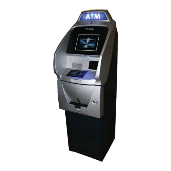
ERVICE ANUAL The Triton ARGO ATM is a lobby terminal designed for indoor use only. The ARGO line includes models RL1713, RL27XY, and RL63XY. The following sections provide instructions and tips to understand and service the ARGO ATM. Only trained and certifi ed technicians should be providing service to the Triton ARGO product line. -
Page 5: Contact Information
Mail/RMAs: ATMGurus 21405 B Street Long Beach, MS USA 39560 Please include your RMA number on any return shipments. Your RMA is your tracking identification. This document may not be reproduced or distributed without the express written consent of Triton. -
Page 6: Model Series
ARGO S ERVICE ANUAL ARGO MODEL SERIES The ARGO line of ATMs by Triton includes a robust variety of features on the several models available. The table below is provided for service technicians to more easily identify models. CABINET/ BUSINESS HOURS... -
Page 7: Product Overview
Touch reactive F keys LCD color Keypad T7 Triple DES and PCI compliant EPP T5 Triple DES and PCI compliant EPP ARGO 12 This document may not be reproduced or distributed without the express written consent of Triton. - Page 8 ARGO S ERVICE ANUAL High Topper Sign Integrated Topper Function Keys Earphone Jack Lead-through LED Indictors Bill Tray Fascia Key Lock Fascia ARGO 7 ARGO 12 This document may not be reproduced or distributed without the express written consent of Triton.
- Page 9 Single drawer cassette—no lock < 100 reject bin capacity 5 notes per second max dispense rate The MiniMech dispenser sits on a fixed tray. This document may not be reproduced or distributed without the express written consent of Triton.
- Page 10 Deeper than the SCDU 200 note reject NMD50 1750 note capacity per cassette Two-Four cassettes 200 note reject 5 notes per second This document may not be reproduced or distributed without the express written consent of Triton.
- Page 11 ARGO S ERVICE ANUAL ARGO 7 CONTROL PANEL Power Supply Modem Product Label Printer Controller Card Reader Speaker Printer / Cutter Assemblies Display Mainboard This document may not be reproduced or distributed without the express written consent of Triton.
- Page 12 Product Label Printer Controller Card Reader Printer / Cutter Assemblies Speaker Docking PCMCIA Card Slot Board (Under Black Tab) Display Assembly Mainboard Mainboard Quick Release Bar This document may not be reproduced or distributed without the express written consent of Triton.
-
Page 13: Wiring Diagram
: ARGO 7 M IRING IAGRAM ODELS System interconnect (wiring) diagram ONLY. This may not reflect the actual physical location of the connectors on the subassembly. This document may not be reproduced or distributed without the express written consent of Triton. - Page 14 : ARGO 12 M IRING IAGRAM ODELS System interconnect (wiring) diagram ONLY. This may not reflect the actual physical location of the connectors on the subassembly. This document may not be reproduced or distributed without the express written consent of Triton.
- Page 15 Mainboard for ARGO 12: Triton’s X2 technology © Microsoft Windows CE 5.0 OS RAM: 128 MB Flash Memory: 128 MB TCP/IP—10BASE-T/100BASE-TX This document may not be reproduced or distributed without the express written consent of Triton.
-
Page 16: General Troubleshooting
NOTE: The LEDs for the ARGO 7 mainboard were introduced on Rev. D version. The revi- sion version may be found on the label on the mainboard as shown. This document may not be reproduced or distributed without the express written consent of Triton. - Page 17 RX indicates communication from the applicable device to the mainboard. Each TX and RX LED has a dual color capacity of green and red. This document may not be reproduced or distributed without the express written consent of Triton.
- Page 18 When LED3 and LED1 are on while LED2 is off, this indicates a printer error has occurred, e.g., out of paper, and attention is needed. Printer control board showing LED3 and LED2 on, ready for service. (Clear plastic cover removed.) This document may not be reproduced or distributed without the express written consent of Triton.
- Page 19 When off, it may simply mean a sleep mode awaiting activity. This document may not be reproduced or distributed without the express written consent of Triton.
- Page 20 If there is a problem with the power supply or the voltages, the unit cannot be serviced in the field. Replace the power supply unit. This document may not be reproduced or distributed without the express written consent of Triton.
- Page 21 IP addresses ports (both local and host processor), terminal ID, master keys, etc. (See Basic Setup of the Triton ATMs or the XScale/X2 Configuration Manual for more information about the programming setup of the Triton ATMs.) Unless the communication is configured properly, expect communication is-...
- Page 22 (e.g., your cell phone) on the test screen (Main Menu > Diagnostics > Modem/ Ethernet > Test). 6. To verify data transfer between modem and host, download Working Keys (Main Menu > Key Management > Download Working Keys). This document may not be reproduced or distributed without the express written consent of Triton.
- Page 23 Keypad > 2-Test). NOTE: DO NOT attempt to remove the back from the customer keypad to open the keypad! This will render the keypad useless. This document may not be reproduced or distributed without the express written consent of Triton.
- Page 24 1. On the Management Functions Main Menu, press 6 (Terminal Configuration). 2. Press 5 (ISO/Surcharge Properties). 3. Determine if the associated ISO number for the bank is setup properly and correct where necessary. This document may not be reproduced or distributed without the express written consent of Triton.
-
Page 25: Section 2: Error Codes
2: E ECTION RROR ODES... -
Page 26: Error Codes
ARGO S ERVICE ANUAL Error codes are listed in the table below in numeric order. Suggested corrective actions to resolve the issue are noted along with each code. In addition, reference aids for many of the corrective actions are provided. These aids are found in the General Troubleshooting and Major Components sections of this manual. - Page 27 ARGO S ERVICE ANUAL CODE DESCRIPTION/CAUSE ACTION REFERENCE Exit sensor is covered for a 1) Inspect the note transport and delivery General Access longer than allowed time for throat. General Troubleshooting: the current notes. 2) Make sure all belts are on track and Cash Dispenser Errors Note too long at exit there are no documents jammed in the...
- Page 28 ARGO S ERVICE ANUAL CODE DESCRIPTION/CAUSE ACTION REFERENCE Exit sensor blocked or faulty 1) Remove any jammed notes at exit General Access throat or sensor. Jam at exit Major Components: Cash 2) Clean exit sensor(s) and check wire Dispenser Unit connectivity.
- Page 29 ARGO S ERVICE ANUAL CODE DESCRIPTION/CAUSE ACTION REFERENCE Clearance door open. 1) Check the clearance doors. Check the General Access Jammed note(s). Exit sensor knobs that latch the doors in place. Replace General Troubleshooting: dirty/faulty. any knobs that are cracked or broken. Cash Dispenser Errors (TDM Click Counter 40 - 2) Inspect for and remove jammed note(s)
- Page 30 ARGO S ERVICE ANUAL CODE DESCRIPTION/CAUSE ACTION REFERENCE Not enough notes picked 1) Perform the Learn Operation (Relearn General Access during learn operation were Bill Thickness found on the Cassette General Troubleshooting: within a specifi c range of Parameters menu). The problem notes are Cash Dispenser Errors thickness.
- Page 31 ARGO S ERVICE ANUAL CODE DESCRIPTION/CAUSE ACTION REFERENCE Width sensor did not detect 1) Verify current TDM fi rmware version General Access note. Skewed note. Broken and load if necessary. General Troubleshooting: wires on width sensor 2) Remove the cassette(s) and inspect the Cash Dispenser Errors harness note path for skewed note coming from the...
- Page 32 ARGO S ERVICE ANUAL CODE DESCRIPTION/CAUSE ACTION REFERENCE Jammed note(s). Diverter 1) Inspect for and remove jammed General Access sensor fault. Dispenser tray currency at the diverter. Verify the diverter General Troubleshooting: not properly mounted. moves freely. Cash Dispenser Errors Diverter Timeout 2) Inspect the diverter sensor and check Major Components: Cash...
- Page 33 ARGO S ERVICE ANUAL CODE DESCRIPTION/CAUSE ACTION REFERENCE Note detected at exit sensor 1) Inspect for and remove note(s) or General Access during purge. Dirty/faulty foreign objects at the exit sensor. General Troubleshooting: exit sensor. 2) Inspect the exit sensor and clean if Cash Dispenser Errors Exit blocked at purge necessary.
- Page 34 ARGO S ERVICE ANUAL CODE DESCRIPTION/CAUSE ACTION REFERENCE Jammed note(s). Dispenser 1) Inspect for and remove jammed General Access tray not properly mounted. currency in the feed path and at the exit General Troubleshooting: sensor. Timeout waiting for notes Cash Dispenser Errors to divert 2) Run Purge/Test Dispense commands.
- Page 35 ARGO S ERVICE ANUAL CODE DESCRIPTION/CAUSE ACTION REFERENCE Exit sensor loose. 1) Inspect the exit sensor for proper General Access Interference at the exit mounting. General Troubleshooting: sensor (may have been 2) Look for foreign objects near the exit Cash Dispenser Errors caused by customer having sensor.
- Page 36 ARGO S ERVICE ANUAL CODE DESCRIPTION/CAUSE ACTION REFERENCE Note(s) jammed in 1) Inspect for and remove note(s) jammed General Access extension. Unfi t notes. White in the extension; check for notes in the General Troubleshooting: pinch rollers not seated diverter area. Cash Dispenser Errors properly.
- Page 37 ARGO S ERVICE ANUAL CODE DESCRIPTION/CAUSE ACTION REFERENCE Jammed notes, sensor dirty 1) Inspect the feed path and feed General Access or faulty. sensor for jammed currency and broken General Troubleshooting: components. Status reported exit blocked Cash Dispenser Errors 2) Clean the sensor with soft brush or Same as error 134 Major Components: Cash vacuum cleaner.
- Page 38 The Triton Connect host connects to the line before the terminal. computer generates the error 2) Check to ensure the “Triton Connect” when the terminal does not function is enabled in Management respond to a telephone call Functions.
- Page 39 See XScale/X2 Confi guration downloaded from host. working keys from host. Manual Communications key not confi gured Basic Setup of the Triton Terminal ID not confi gured 1) Confi gure terminal ID. ATMs This error code is often 1) Enter master keys.
- Page 40 ARGO S ERVICE ANUAL CODE DESCRIPTION/CAUSE ACTION REFERENCE Card reader cable faulty 1) Inspect the card reader. Make sure there General Access or disconnected. Foreign is no foreign material in the card slot. Major Components: Card matter in the card reader. 2) Clean the card reader with a cleaning Reader Card reader dirty or faulty.
- Page 41 3) If you are not using TCP/IP for or external TCP/IP modem. transactions or Triton Connect, ensure you Lost TCP Host are confi gured for telephone operation. Out going communications 1) Verify your communications settings seems to be successful, and external TCP/IP equipment.
- Page 42 SPED Self Test error General Troubleshooting: Keypad Issues The SPED has returned a 1) If accessible, check the battery voltage warning message to Triton (3VDC). Major Components: Connect that the SPED Customer Keypad 2) Ensure the battery is seated securely in battery is low.
- Page 43 ARGO S ERVICE ANUAL CODE DESCRIPTION/CAUSE ACTION REFERENCE Low number of notes in 1) Remove and refi ll the affected General Access cassettes. This is a warning cassette(s). Refi lling may be delayed for General Troubleshooting: message. It will not place several transactions if the error code is Cash Dispenser Errors the cash dispenser out of...
- Page 44 ARGO S ERVICE ANUAL CODE DESCRIPTION/CAUSE ACTION REFERENCE Unfi t notes or note feeder 1) Check condition of the currency. General Access error 2) Verify that the cassettes are operating General Troubleshooting: Failure to feed correctly. Replace cassettes as needed. Cash Dispenser Errors 3) Check the operation of the note feeder Major Components: Cash...
- Page 45 ARGO S ERVICE ANUAL CODE DESCRIPTION/CAUSE ACTION REFERENCE Dispenser Offl ine Confi g 1) Reset the dispenser and/or ATM. Record Size Invalid This is a warning code. No action necessary. No notes retracted Cassette has no ID or is 1) Using inject cassette ID, send a new faulty.
- Page 46 The dispenser and then putting it back into the error code will be sent to the dispenser while power is applied to the Triton Connect host if Triton dispenser. Connect feature is enabled. Reject cassette almost full Error in cassette ID.
- Page 47 ARGO S ERVICE ANUAL CODE DESCRIPTION/CAUSE ACTION REFERENCE Note qualifi er faulty. 1) Verify that the cable that connects the General Access Double detect sensor faulty, double detect module to the CMC module General Troubleshooting: dirty, or disconnected. is undamaged and connected at both ends. Cash Dispenser Errors Note qualifi...
- Page 48 fi rmware and terminal incompatibilities between terminal software software. and dispensing mechanism fi rmware. Communications time-out 4) Contact Triton Technical Support. Dispenser - Data size error 1) Restart the terminal. 2) Attempt to reset the terminal error code. Dispenser - Read error...
- Page 49 ARGO S ERVICE ANUAL CODE DESCRIPTION/CAUSE ACTION REFERENCE Requested amount may 1) Enter a smaller value. General Access have exceeded dispenser’s 2) If error persists, it may be necessary to General Troubleshooting: capability (50 notes per replace the dispenser mechanism. Cash Dispenser Errors request) Major Components: Cash...
- Page 50 Check Op status 3) Use the NMD test software (available Dispenser data corrupt. to Triton Certifi ed Service Technicians) CMC fault. and verify the operational error code of the dispenser. Dispenser Offl ine - Storing confi...
- Page 51 ARGO S ERVICE ANUAL CODE DESCRIPTION/CAUSE ACTION REFERENCE Same cassette IDs installed, 1) Verify each cassette ID. See XScale/X2 e.g., 2 cassette “A”s. NMD Confi guration Manual 2) Replace cassette or inject new cassette dispenser allows for only one of each cassette ID to be installed.
- Page 52 5) Reboot the ATM. request 6) If the error persists, replace the card NOTE: Report this error reader. to Triton Tech Support. No data read from any of the tracks on the card. Card Reader - No data Unknown cause...
- Page 53 Card Reader - Device received invalid request Software error Card Reader - Device offl ine NOTE: Report this error to Triton Tech Support. Card Reader - Device reset Unknown cause Card Reader - System timeout Terminal power supply 1) Check operation and voltages of the General Access surged or faulty.
- Page 54 ARGO S ERVICE ANUAL CODE DESCRIPTION/CAUSE ACTION REFERENCE Too many or excessively 1) Check available memory in See XScale/X2 large graphics stored in fl ash Management Functions (Main Menu > Confi guration Manual memory 5-System Parameters > 8-Statistics). The hard disk space is low 2) Delete any unused graphic fi...
- Page 55 ARGO S ERVICE ANUAL CODE DESCRIPTION/CAUSE ACTION REFERENCE Faulty, damaged, or 1) Inspect cable from mainboard assembly General Access disconnected SPED cable(s). to the SPED module for damage. Make General Troubleshooting: Mainboard or SPED faulty sure that the cable is connected at both Keypad Issues ends.
- Page 56 ARGO S ERVICE ANUAL CODE DESCRIPTION/CAUSE ACTION REFERENCE SPED cables loose or 1) Inspect cable from mainboard to the See General damaged. DC voltages SPED module for damage. Make sure that Troubleshooting: Blank incorrect the cable is connected at both ends. Screen for voltages.
- Page 57 2) Download working keys. working key before loading 3) If the error condition persists, verify the the corresponding master application code and SPED versions, then Basic Setup of the Triton key. replace the SPED. ATMs SPED reported parent key not loaded...
- Page 58 ARGO S ERVICE ANUAL CODE DESCRIPTION/CAUSE ACTION REFERENCE Battery Low 1) If the unit has been unplugged for some General Access time (> 3 months), it is possible the battery SPED self test Battery low General Troubleshooting: just needs to be recharged. If this is the status Keypad Issues case, the error won’t be able to be cleared...
- Page 59 ARGO S ERVICE ANUAL CODE DESCRIPTION/CAUSE ACTION REFERENCE SPED unrecoverable device tamper A cassette is low in cash 1) Replenish cash in cassette. See User Manual Dispenser – Cassette is low All cassettes are low in cash 1) Replenish cash in all cassettes. Dispenser –...
- Page 60 ARGO S ERVICE ANUAL CODE DESCRIPTION/CAUSE ACTION REFERENCE Sensor blocked, tripped 1) Clear any jammed bills in the exit General Access sensor. (Sometimes caused by customer Dispenser – Sensor remains General Troubleshooting: putting fi ngers in exit while cash is covered.
- Page 61 ARGO S ERVICE ANUAL COMMUNICATION ERROR CODES Below are the Communication Error Codes. These are communication errors which may only be found in the journal and not on the terminal screen. These issues often are temporary, but when they become persistent, action steps are provided.
- Page 62 3) Contact host to verify handshake expired. protocol. Communications error - Time out waiting for EOT Triton Connect calls only - modem lost carrier signal. Communications error - Communications problem EOT from processor was not received within time out period.
- Page 63 ARGO S ERVICE ANUAL CODE DESCRIPTION/CAUSE ACTION REFERENCE Modem response was 1) Verify/test phone line connections and General Access good, but operation was not cables. Communication performed. This is normally 2) Confi rm correct modem setup in Issues: Basic Dialup an internal terminal problem.
- Page 64 ARGO S ERVICE ANUAL CODE DESCRIPTION/CAUSE ACTION REFERENCE Request was sent but no 1) Verify setup of host phone numbers. General Access response received after the 2) Verify/test phone line connections. Communication specifi ed time (60 seconds). Issues: Basic Dialup 3) Verify quality of phone line (noise, Communications error - No Communication Checks...
-
Page 65: Section 3: Component Service
3: C ECTION OMPONENT ERVICE... - Page 66 This section provides some instructions to assist in the service of various components of the ARGO ATM. The ARGO series of Triton’s ATMs has a very robust mix of possible options. If the particular component/device you need to service is not listed here, contact Triton’s Technical Support for assistance.
- Page 67 ARGO S ERVICE ANUAL 3. Rotate the dial to the right (clockwise) until it 4. For Business Hour Cabinet: Lift up on the cannot move. (around the 90 mark) door handle and pull the door open while the latch is up. NOTE: The opening mark is used to open...
- Page 68 ROPER HUTDOWN ROCEDURES Many service calls to the ATM require shutting down the unit for both damage prevention and safety. Triton software detects abnormal shutdowns and reports these in the journal entries along with the number of normal shutdowns. WARNING: Abnormal shutdowns could cause an internal fi...
- Page 69 ARGO S ERVICE ANUAL 4. Press ENTER to confi rm at the prompt. 5. When the following popup message appears, press the power switch inside the cabinet to the OFF position. Press O on the switch to turn Off. Single Power Supply Dual Power Supply The ATM runs on a computer with an embedded Windows CE 5.0 operating system.
-
Page 70: Major Components
ARGO S ERVICE ANUAL AJOR OMPONENTS The following instructions focus on service to the major components of the ATM. These include: Power Supply Mainboard Display (LCD) Printer Cash Dispenser Card Reader Function Keypad Customer Keypad Cabinet / Vault... - Page 71 ARGO S ERVICE ANUAL OWER UPPLY There are two types of power supplies for the ARGO, the smaller single power supply is found on those ATMs with the MiniMech or SCDU dispenser and the larger dual power supply is found on all other ARGO units. INGLE OWER UPPLY...
- Page 72 ARGO S ERVICE ANUAL OWER UPPLY The dual power supply is found in ARGO ATMs with SDD, NMD50, or HCDU dispensers. All connections, both input and output, are on the front side of the power supply unit. ON/OFF switch AC power IN Optional Power A direct feed...
- Page 73 ARGO S ERVICE ANUAL AINBOARD The mainboard includes the Central Processing Unit (CPU) and all its associated circuitry. It distributes logic voltage and contains the interface circuitry between the CPU and all of the other devices within the terminal. Since the mainboard communicates with all of the devices in the terminal, if the problem is not the device itself, the mainboard may be the cause of any generalized communication errors.
-
Page 74: Cash Dispensers
ARGO S ERVICE ANUAL ARGO 7 M AINBOARD SSEMBLY ONNECTIONS USB Ports (Printer, “ATM” sign Modem, and auxillary) Ethernet Keypad (EPP) Dispenser Headphone Jack Printer Power Card Reader Power LEDs Door • Keypad Switch • Card Reader • Printer • Cash Dispenser... - Page 75 ARGO S ERVICE ANUAL ARGO 12 M AINBOARD OCKING OARD SSEMBLY ONNECTIONS Mainboard side views Ethernet USB Ports Connections to Docking Board Connections to Mainboard Docking Board Door Switch “ATM” sign Power Printer Dispenser Headphone Modem Function Keys Jack Card Reader LEDs Printer •...
- Page 76 ARGO S ERVICE ANUAL ARGO 7 M OW TO EMOVE THE AINBOARD Tools: 1 - #2 Phillips screwdriver 1. Perform steps in Proper Shutdown Procedures and How to Access Components Behind the Fascia. 2. Disconnect all cables and wiring from the mainboard. 3.
- Page 77 ARGO S ERVICE ANUAL ARGO 12 M OW TO EMOVE THE AINBOARD Tools: 1 - #2 Phillips screwdriver (long neck needed) 1. Perform steps in Proper Shutdown Procedures and How to Access Components Behind the Fascia. 2. Disconnect the Ethernet cable and any USB cables connected to the mainboard. 3.
- Page 78 ARGO S ERVICE ANUAL ARGO 12 D OW TO EMOVE THE OCKING OARD Tools: 1 - #1 Phillips screwdriver 1. Perform steps in Proper Shutdown Procedures and How to Access Components Behind the Fascia. 2. After removing the mainboard, disconnect all cables/wires from the docking board. 3.
- Page 79 ARGO S ERVICE ANUAL (LCD) ISPLAY The ARGO 7 is a 7” capacitive touch color LCD screen. Almost all functions can be performed by touching the screen like a portable tablet. (Password entry is always performed on the keypad.) ARGO 7 Display front ARGO 7 Display back The ARGO 12 is a 12.1”...
- Page 80 ARGO S ERVICE ANUAL ARGO 7 D OW TO EMOVE THE ISPLAY ONITOR Tools: 1 - #2 Phillips screwdriver 1. Perform steps in Proper Shutdown Procedures and How to Access Components Behind the Fascia. Perform steps in How to Remove the ARGO 7 Mainboard. 2.
- Page 81 ARGO S ERVICE ANUAL ARGO 12 D OW TO EMOVE THE ISPLAY ONITOR Tools: 1 - #2 Phillips screwdriver 1. Perform steps in Proper Shutdown Procedures and How to Access Components Behind the Fascia. Perform steps in How to Remove the ARGO 12 Mainboard. 2.
- Page 82 ARGO S ERVICE ANUAL 7. With the display monitor free from the bracket, turn the monitor over and disconnect the LCD cable. Squeeze each end of the connector to release and pull out the cable. Squeeze each end of the connector simultaneously and pull out connector.
- Page 83 ARGO S ERVICE ANUAL RINTER The ARGO series uses either a 60 mm thermal printer (Seiko LPT2242) or a 80 mm thermal printer (Seiko LPT 2342). 60 mm Printer 80 mm Printer The same PCB is used for both of these printers. All connections are the same for both printers. Printer PCB Printer PCB connections The printer assembly consists of four (4) primary components:...
- Page 84 ARGO S ERVICE ANUAL The general specifi cations of the two printers are indicated in the table below. FEATURE (LPT2242) (LPT2342 Print Method Thermal Thermal Printable Dots Per Line Resolution 8 dots per mm 8 dots per mm Print Speed 90 mm / sec 75 mm / sec Print Width...
- Page 85 ARGO S ERVICE ANUAL 4. Select 2 - Reset/Test Printer to print a test receipt. If all external error conditions have been checked and corrected as applicable, and the printer passed the Self Test feature, there may be a problem with the mainboard, or the printer data communication cable from the mainboard to the printer controller.
- Page 86 ARGO S ERVICE ANUAL OW TO EMOVE THE RINTER ONTROLLER Tools: 1 - #2 Phillips screwdriver 1. Perform steps in Proper Shutdown Procedures and How to Access Components Behind the Fascia. 2. Disconnect the Printer Power cable and the Printer USB cable from the printer. 3.
- Page 87 ARGO S ERVICE ANUAL OW TO EMOVE THE ECEIPT APER UTTER Tools: 1 - #2 Phillips screwdriver 1 - TY Wrap cutter 1. Perform steps in Proper Shutdown Procedures and How to Access Components Behind the Fascia. 2. Remove the receipt paper from the printer mechanism. Open the printer by pulling and holding the locking pin out and rotating the printer open.
- Page 88 ARGO S ERVICE ANUAL OW TO EMOVE THE ECEIPT APER UTTER CONT 6. Gently pull back on the black plastic pressure clips at the front left and right corners of the cutter that help secure it to the mounting 7. With the pressure clips released, gently pull bracket.
- Page 89 ARGO S ERVICE ANUAL OW TO EMOVE THE RINTER ECHANISM Tools: 1 - #2 Phillips screwdriver 1 - TY Wrap cutter 1. Follow the procedures for “How to Remove the Receipt Paper Auto Cutter”. 2. Cut the TY Wrap that bundle the wires from the print mechanism and the cutter together. (printer/cutter removed from assembly for clarity) 3.
- Page 90 ARGO S ERVICE ANUAL OW TO EPLACE THE RINTER ECHANISM 1. Follow the procedures backwards for “How to Remove the Printer Mechanism”. NOTE: Before securing both ground wires to the printer mechanism with one screw, ensure the cables are routed through the notch under the printer to avoid pinching them. 2.
- Page 91 ARGO S ERVICE ANUAL ISPENSER Dispensing Mechanisms • MiniMech • NMD 50 • Single cassette • Dual cassette • 750 - 1000 note capacity • 1750 - 2000 note capacity • < 100 reject bin capacity • < 100 reject bin capacity •...
- Page 92 ARGO S ERVICE ANUAL Removing the MiniMech Dispensing Mechanism Tools: 1 - #2 Phillips screwdriver 1 - small slotted screwdriver 1. Follow Proper Shutdown Procedures and steps in How to Access Components Behind the Fascia. 2. Remove the cassette from the dispensing mechanism. 3.
- Page 93 ARGO S ERVICE ANUAL Installing the MiniMech Dispensing Mechanism Tools: 1 - #2 Phillips screwdriver 1 - small slotted screwdriver 1. Follow Proper Shutdown Procedures and steps in How to Access Components Behind the Fascia. 2. Remove the cassette from the dispensing mechanism. 3.
- Page 94 ARGO S ERVICE ANUAL Removing the SDD Dispensing Mechanism Tools: 1 - Pliers (to use on wing nut if needed) 1. Follow Proper Shutdown Procedures and steps in How to Access Components Behind the Fascia. 2. Remove the cassette from the dispensing mechanism. 3.
- Page 95 ARGO S ERVICE ANUAL Installing the SDD Dispensing Mechanism Tools: 1 - Pliers (to use on wing nut if needed) 1. Follow Proper Shutdown Procedures and steps in How to Access Components Behind the Fascia. 2. If the wing nuts were previously installed onto the posts, remove them and set aside. 3.
-
Page 96: Nmd50 Dispenser
NMD50 dispensing mechanisms. Unauthorized repairs to the NMD50 dispensing mechanism may void the factory warranty. Contact the Triton Systems Technical Support Department for additional information. Factory trained service technicians should refer to the NMD50 Dispenser Mechanism Service Manuals for further instructions. - Page 97 ARGO S ERVICE ANUAL Removing the NMD50 Dispensing Mechanism cont... 4. Unplug the Dispenser Communication cable and the Dispenser Power Cable from the side of the dispenser. 5. Remove all the cables from the cable clips along the side and rear of the dispenser. Route the cables over the cabinet door to prevent damage.
- Page 98 ARGO S ERVICE ANUAL SCDU Removing the SCDU Dispensing Mechanism Tools: 1 - #2 Phillips screwdriver 1. Follow Proper Shutdown Procedures and steps in How to Access Components Behind the Fascia. 2. Remove the cassette from the dispensing mechanism. Extend the dispenser slides. 3.
- Page 99 ARGO S ERVICE ANUAL Installing the SCDU Dispensing Mechanism Tools: 1 - #2 Phillips screwdriver 1. Follow Proper Shutdown Procedures and steps in How to Access Components Behind the Fascia. 2. Remove the cassette from the dispensing mechanism. Extend the dispenser slides. 3.
- Page 100 ARGO S ERVICE ANUAL HCDU ** WARNING ** Due to the weight of the dispenser, the HCDU should be lifted from the rails by TWO service personnel. Removing the HCDU Dispensing Mechanism Tools: None 1. Follow Proper Shutdown Procedures and steps in How to Access Components Behind the Fascia. 2.
- Page 101 ARGO S ERVICE ANUAL Installing the HCDU Dispensing Mechanism Tools: None 1. Follow Proper Shutdown Procedures and steps in How to Access Components Behind the Fascia. 2. Remove the cassettes from the dispensing mechanism. Extend the dispenser slides. 3. Route the cables over the cabinet door to prevent damage. TWO Service Personnel: Using the attached handles, carefully lift the dispenser onto the rails...
-
Page 102: Scdu & Hcdu Troubleshooting
ARGO S ERVICE ANUAL SCDU SCDU & HCDU NOTE: The information here concerns the Hantle manufactured dispensers found in the ARGO. Since both the SCDU and HCDU are Hantle made, there is much similarity in their mechanisms. Most of the steps for resolving SCDU issues may be applied to the HCDU. - Page 103 ARGO S ERVICE ANUAL Disconnect the data and power cables to the SCDU/HCDU. Switch back on the ATM. The initialization process will begin but suspend and warn of the defective dispenser. Fortunately, most fatal dispenser errors can be remedied by replacing the circuit board rather than the entire dispenser.
- Page 104 ARGO S ERVICE ANUAL There are four DIP switches on the SCDU and HCDU mainboard and two DIP switches on the ultrasonic double detect sensor board. For normal operation, only the third [3] DIP switch on the SCDU/HCDU board should be in the “OFF” position. All others should be set to “ON”. Both of the DIP switches on the ultrasonic double detect sensor board should be in the “OFF”...
- Page 105 ARGO S ERVICE ANUAL How to Remove the Mainboard cont... 3. Loosen, do not remove, the four screws securing the mainboard cover. Lift the mainboard cover from the unit. 4. Disconnect all cables from the mainboard. 5. Remove the four screws that secure the mainboard.
- Page 106 ARGO S ERVICE ANUAL How to Remove the Ultrasonic Double Detect Sensor Board NOTE: The actions shown here for the SCDU are similar for the HCDU. Tools: 1 - #1 Phillips screwdriver 1. Perform steps 1 - 6 in How to Remove the Mainboard. 2.
- Page 107 ARGO S ERVICE ANUAL How to Remove the Ultrasonic Double Detect Sensors NOTE: The actions shown here for the SCDU are similar for the HCDU. There are two ultrasonic double detect sensors on the SCDU/HCDU, each facing the other. They are found in the back of the SCDU/HCDU. The steps apply to both of these sensors.
- Page 108 ARGO S ERVICE ANUAL How to Remove the Encoder Sensors NOTE: The actions shown here for the SCDU are similar for the HCDU. The encoder sensor and the gate operation detection sensor are identical. If one is immediately unavailable in the fi eld, the other can be substituted.
- Page 109 ARGO S ERVICE ANUAL How to Remove the Gate Operation Detection Sensor NOTE: The actions shown here for the SCDU are similar for the HCDU. The gate operation detection sensor is the same sensor used for the encoder sensor. These parts can be interchanged in the fi...
- Page 110 ARGO S ERVICE ANUAL How to Remove the SCDU Main Motor NOTE: The actions shown here for the SCDU are similar for the HCDU. Tools: 1 - #1 Phillips screwdriver 1. Perform steps 1 - 6 in How to Remove the Mainboard. 2.
- Page 111 ARGO S ERVICE ANUAL How to Remove the Gate Solenoid Unit NOTE: The actions shown here for the SCDU are similar for the HCDU. Tools: 1 - #1 Phillips screwdriver 1. Perform steps 1 - 6 in How to Remove the Mainboard. 2.
- Page 112 ARGO S ERVICE ANUAL How to Swap HCDU Cassettes The HCDU cassettes are identical except for the rail position on the sides. On the two cassette HCDU, the rail of the upper cassette (#1) is in the high position and the rail of the lower cassette (#2) is in the lower position.
- Page 113 ARGO S ERVICE ANUAL How to Make Height Adjustments on HCDU Cassettes for Canada When necessary, an HCDU cassette confi gured for the U.S. may be converted for Canadian currency by simply adjusting the height rails of the cassette. Tools: 1 - #2 Phillips screwdriver 1.
-
Page 114: Card Reader
ARGO S ERVICE ANUAL EADER 1-2 C OW TO EMOVE THE RACK EADER 1. Follow Proper Shutdown Procedures and steps in How to Access Components Behind the Fascia. 2. Push the AC power ON/OFF switch on the power supply to the OFF position. Cut the TY Wrap holding the card reader cable to the assembly. - Page 115 ARGO S ERVICE ANUAL EMV C OW TO EMOVE THE EADER 1. Follow Proper Shutdown Procedures and steps in How to Access Components Behind the Fascia. 2. Push the AC power ON/OFF switch on the power supply to the OFF position. Unclick the locking tabs from the card reader cable.
- Page 116 ARGO S ERVICE ANUAL 1-2 C RACK EADER ROUBLESHOOTING The magnetic card reader for the ARGO is a dip type reader. The standard card reader for the US is a Magtek Serial MCR (Track 1-2). There is also an optional Sankyo 330 EMV dip style card reader. Generally if a problem occurs with the card reader, fi...
-
Page 117: Function Keypad
ARGO S ERVICE ANUAL UNCTION EYPAD The Function Keypads are only found in the ARGO 12 unit. The ARGO 7 unit has a touchscreen keypad in the display and therefore has no use for the function keypads. The function keys CANNOT be purchased seperately. - Page 118 ARGO S ERVICE ANUAL ARGO 12 F OW TO EPLACE THE UNCTION EYPADS Tools: 1 - #2 Phillips screwdriver If the gaskets do not need replacing, skip to Step 3. NOTE: The gaskets are specifi c to each side. Before removing the paper backing, determine the TOP from the BOTTOM by comparing the length of the sides.
- Page 119 ARGO S ERVICE ANUAL ARGO 12 F OW TO EPLACE THE UNCTION EYPADS CONT 4. Install the glass assembly onto the display by lining up the glass with the tabs on the display bracket. Use short burst of compressed air if necessary to remove debris.
-
Page 120: Customer Keypad (Epp)
PIN (Personal Identifi cation Number) entry and processing management. It stores the PIN Master Key and Working Key when appropriately setup. See the XScale/X2 Confi guration Manual or the Basic Setup of the Triton ATMs for information about entering Master Keys and downloading Working Keys for the ATM. - Page 121 ARGO S ERVICE ANUAL The EPP communication data cable is also the power source for the EPP and should be securely connected to the mainboard and the RJ-45 connector on the EPP assembly. The left and right function keys unite into one common connector in the EPP.
- Page 122 ARGO S ERVICE ANUAL TEPS FOR AMPER RROR ODES CONT 4. Perform a keypad test from the Management Functions Main Menu: • Press 2 - Diagnostics • Press 8 - Keypad 5. Check the device status from the Management • Press 2 - Test Functions Main Menu: •...
- Page 123 Confi gured). At this point, re-enter the Master Key and download the Working Key. See XScale / X2 Confi guration Manual or the Basic Setup of the Triton ATMs for information about entering Master Keys and downloading Working Keys for the ATM.
- Page 124 ARGO S ERVICE ANUAL T7 PCI EPP K OW TO EPLACE THE ATTERY IN THE EYPAD The battery in the EPP may be removed without risk of damage but there is ONLY a 2 - 5 minute window of time to replace it with a spare battery before losing stored data (passwords and keys).
- Page 125 ARGO S ERVICE ANUAL T5 PCI EPP K OW TO EPLACE THE ATTERY IN THE EYPAD DO NOT remove the battery from the T5 EPP without FIRST connecting a new battery!! This EPP will be permanently damaged if battery is removed and keypad unpowered before connecting a new battery.
- Page 126 ARGO S ERVICE ANUAL OW TO EMOVE THE USTOMER EYPAD Tools: 1 - #2 Phillips screwdriver 1. Follow Proper Shutdown Procedures and steps in How to Access Components Behind the Fascia. 2. Disconnect the cables to the EPP. 3. Remove the six mounting screws, three on each side of the keypad.
-
Page 127: Cabinet / Vault (Lower Cabinet)
ARGO S ERVICE ANUAL ABINET AULT OWER ABINET See How to Access the Cabinet / Vault (mechanical and electronic) in the General Access section of this manual for instructions on opening the cabinet / vault. OW TO ET THE ABINET AULT OMBINATION ECHANICAL... - Page 128 ARGO S ERVICE ANUAL OW TO ET THE ABINET AULT OMBINATION ECHANICAL CONT 6. Rotate the dial to the left (counterclockwise) 2 times, stopping on the third NEW combination number at the changing index. revolutions 7. When the new combination has been set, rotate the changing bar/key counterclockwise;...
- Page 129 ARGO S ERVICE ANUAL OW TO ET THE ABINET AULT OMBINATION LECTRONIC The electronic combination lock from the factory may be either a dead bolt type (high security vault units) or a swing bolt type (business hour units). The basic programming is the same for both of these types. For the dead bolt, once the successful combination is entered, the face of the lock is turned clockwise to release the lock before the door handle can be turned.
- Page 130 ARGO S ERVICE ANUAL HAT TO DO HEN THE ATTERY IS Repeated beeping during an opening indicates that the battery is low and needs to be replaced. It is recommended that the battery is replaced at least twice annually. Replacing the Battery on a Dead Bolt Electronic Lock The battery box is located on the back of the cabinet / vault door.
- Page 131 ARGO S ERVICE ANUAL HAT TO DO HEN THE PERATE If the cabinet / vault door is closed and locked but the lock will not operate, the lock must be energized from the two external terminals on the combination keypad. NOTE: For these steps to work, battery contact with the external terminal points must be maintained at all times.
-
Page 132: Acronyms
ARGO S ERVICE ANUAL Acronyms Defi nitions provided are those applicable within the context of this document. Acronym Defi nition Americans with Disabilities Act Back Ground Dial Bank Identifi cation Number BIOS Basic Input / Output System Cash Dispenser Unit Control Electronics Computer On and Present Central Processing Unit... - Page 133 Read Only Memory SD Card Secure Digital Card SDRAM Synchronous Dynamic Random Access Memory Slip Handling Unit (receipt printer) SPED Secured PIN Entry Device (EPP) SRAM Static Random Access Memory TDES Triple Data Encryption Standard Triton Dynamic Language Thin File Transistor...
- Page 134 ARGO S ERVICE ANUAL ISPENSER Dispensing Mechanisms • MiniMech • NMD 50 • Single cassette • Dual cassette • 750 - 1000 note capacity • 1750 - 2000 note capacity • < 100 reject bin capacity • < 100 reject bin capacity •...
- Page 135 ARGO S ERVICE ANUAL Removing the MiniMech Dispensing Mechanism Tools: 1 - #2 Phillips screwdriver 1 - small slotted screwdriver 1. Follow Proper Shutdown Procedures and steps in How to Access Components Behind the Fascia. 2. Remove the cassette from the dispensing mechanism. 3.
- Page 136 ARGO S ERVICE ANUAL Installing the MiniMech Dispensing Mechanism Tools: 1 - #2 Phillips screwdriver 1 - small slotted screwdriver 1. Follow Proper Shutdown Procedures and steps in How to Access Components Behind the Fascia. 2. Remove the cassette from the dispensing mechanism. 3.
- Page 137 ARGO S ERVICE ANUAL Removing the SDD Dispensing Mechanism Tools: 1 - Pliers (to use on wing nut if needed) 1. Follow Proper Shutdown Procedures and steps in How to Access Components Behind the Fascia. 2. Remove the cassette from the dispensing mechanism. 3.
- Page 138 ARGO S ERVICE ANUAL Installing the SDD Dispensing Mechanism Tools: 1 - Pliers (to use on wing nut if needed) 1. Follow Proper Shutdown Procedures and steps in How to Access Components Behind the Fascia. 2. If the wing nuts were previously installed onto the posts, remove them and set aside. 3.
- Page 139 NMD50 dispensing mechanisms. Unauthorized repairs to the NMD50 dispensing mechanism may void the factory warranty. Contact the Triton Systems Technical Support Department for additional information. Factory trained service technicians should refer to the NMD50 Dispenser Mechanism Service Manuals for further instructions.
- Page 140 ARGO S ERVICE ANUAL Removing the NMD50 Dispensing Mechanism cont... 4. Unplug the Dispenser Communication cable and the Dispenser Power Cable from the side of the dispenser. 5. Remove all the cables from the cable clips along the side and rear of the dispenser. Route the cables over the cabinet door to prevent damage.
- Page 141 ARGO S ERVICE ANUAL SCDU Removing the SCDU Dispensing Mechanism Tools: 1 - #2 Phillips screwdriver 1. Follow Proper Shutdown Procedures and steps in How to Access Components Behind the Fascia. 2. Remove the cassette from the dispensing mechanism. Extend the dispenser slides. 3.
- Page 142 ARGO S ERVICE ANUAL Installing the SCDU Dispensing Mechanism Tools: 1 - #2 Phillips screwdriver 1. Follow Proper Shutdown Procedures and steps in How to Access Components Behind the Fascia. 2. Remove the cassette from the dispensing mechanism. Extend the dispenser slides. 3.
- Page 143 ARGO S ERVICE ANUAL HCDU ** WARNING ** Due to the weight of the dispenser, the HCDU should be lifted from the rails by TWO service personnel. Removing the HCDU Dispensing Mechanism Tools: None 1. Follow Proper Shutdown Procedures and steps in How to Access Components Behind the Fascia. 2.
- Page 144 ARGO S ERVICE ANUAL Installing the HCDU Dispensing Mechanism Tools: None 1. Follow Proper Shutdown Procedures and steps in How to Access Components Behind the Fascia. 2. Remove the cassettes from the dispensing mechanism. Extend the dispenser slides. 3. Route the cables over the cabinet door to prevent damage. TWO Service Personnel: Using the attached handles, carefully lift the dispenser onto the rails...
- Page 145 ARGO S ERVICE ANUAL SCDU SCDU & HCDU NOTE: The information here concerns the Hantle manufactured dispensers found in the ARGO. Since both the SCDU and HCDU are Hantle made, there is much similarity in their mechanisms. Most of the steps for resolving SCDU issues may be applied to the HCDU.
- Page 146 ARGO S ERVICE ANUAL Disconnect the data and power cables to the SCDU/HCDU. Switch back on the ATM. The initialization process will begin but suspend and warn of the defective dispenser. Fortunately, most fatal dispenser errors can be remedied by replacing the circuit board rather than the entire dispenser.
- Page 147 ARGO S ERVICE ANUAL There are four DIP switches on the SCDU and HCDU mainboard and two DIP switches on the ultrasonic double detect sensor board. For normal operation, only the third [3] DIP switch on the SCDU/HCDU board should be in the “OFF” position. All others should be set to “ON”. Both of the DIP switches on the ultrasonic double detect sensor board should be in the “OFF”...
- Page 148 ARGO S ERVICE ANUAL How to Remove the Mainboard cont... 3. Loosen, do not remove, the four screws securing the mainboard cover. Lift the mainboard cover from the unit. 4. Disconnect all cables from the mainboard. 5. Remove the four screws that secure the mainboard.
- Page 149 ARGO S ERVICE ANUAL How to Remove the Ultrasonic Double Detect Sensor Board NOTE: The actions shown here for the SCDU are similar for the HCDU. Tools: 1 - #1 Phillips screwdriver 1. Perform steps 1 - 6 in How to Remove the Mainboard. 2.
- Page 150 ARGO S ERVICE ANUAL How to Remove the Ultrasonic Double Detect Sensors NOTE: The actions shown here for the SCDU are similar for the HCDU. There are two ultrasonic double detect sensors on the SCDU/HCDU, each facing the other. They are found in the back of the SCDU/HCDU. The steps apply to both of these sensors.
- Page 151 ARGO S ERVICE ANUAL How to Remove the Encoder Sensors NOTE: The actions shown here for the SCDU are similar for the HCDU. The encoder sensor and the gate operation detection sensor are identical. If one is immediately unavailable in the fi eld, the other can be substituted.
- Page 152 ARGO S ERVICE ANUAL How to Remove the Gate Operation Detection Sensor NOTE: The actions shown here for the SCDU are similar for the HCDU. The gate operation detection sensor is the same sensor used for the encoder sensor. These parts can be interchanged in the fi...
- Page 153 ARGO S ERVICE ANUAL How to Remove the SCDU Main Motor NOTE: The actions shown here for the SCDU are similar for the HCDU. Tools: 1 - #1 Phillips screwdriver 1. Perform steps 1 - 6 in How to Remove the Mainboard. 2.
- Page 154 ARGO S ERVICE ANUAL How to Remove the Gate Solenoid Unit NOTE: The actions shown here for the SCDU are similar for the HCDU. Tools: 1 - #1 Phillips screwdriver 1. Perform steps 1 - 6 in How to Remove the Mainboard. 2.
- Page 155 ARGO S ERVICE ANUAL How to Swap HCDU Cassettes The HCDU cassettes are identical except for the rail position on the sides. On the two cassette HCDU, the rail of the upper cassette (#1) is in the high position and the rail of the lower cassette (#2) is in the lower position.
- Page 156 ARGO S ERVICE ANUAL How to Make Height Adjustments on HCDU Cassettes for Canada When necessary, an HCDU cassette confi gured for the U.S. may be converted for Canadian currency by simply adjusting the height rails of the cassette. Tools: 1 - #2 Phillips screwdriver 1.
- Page 157 ARGO S ERVICE ANUAL EADER 1-2 C OW TO EMOVE THE RACK EADER 1. Follow Proper Shutdown Procedures and steps in How to Access Components Behind the Fascia. 2. Push the AC power ON/OFF switch on the power supply to the OFF position. Cut the TY Wrap holding the card reader cable to the assembly.
- Page 158 ARGO S ERVICE ANUAL EMV C OW TO EMOVE THE EADER 1. Follow Proper Shutdown Procedures and steps in How to Access Components Behind the Fascia. 2. Push the AC power ON/OFF switch on the power supply to the OFF position. Unclick the locking tabs from the card reader cable.
- Page 159 ARGO S ERVICE ANUAL 1-2 C RACK EADER ROUBLESHOOTING The magnetic card reader for the ARGO is a dip type reader. The standard card reader for the US is a Magtek Serial MCR (Track 1-2). There is also an optional Sankyo 330 EMV dip style card reader. Generally if a problem occurs with the card reader, fi...
- Page 160 ARGO S ERVICE ANUAL UNCTION EYPAD The Function Keypads are only found in the ARGO 12 unit. The ARGO 7 unit has a touchscreen keypad in the display and therefore has no use for the function keypads. The function keys CANNOT be purchased seperately.
- Page 161 ARGO S ERVICE ANUAL ARGO 12 F OW TO EPLACE THE UNCTION EYPADS Tools: 1 - #2 Phillips screwdriver If the gaskets do not need replacing, skip to Step 3. NOTE: The gaskets are specifi c to each side. Before removing the paper backing, determine the TOP from the BOTTOM by comparing the length of the sides.
- Page 162 ARGO S ERVICE ANUAL ARGO 12 F OW TO EPLACE THE UNCTION EYPADS CONT 4. Install the glass assembly onto the display by lining up the glass with the tabs on the display bracket. Use short burst of compressed air if necessary to remove debris.
- Page 163 PIN (Personal Identifi cation Number) entry and processing management. It stores the PIN Master Key and Working Key when appropriately setup. See the XScale/X2 Confi guration Manual or the Basic Setup of the Triton ATMs for information about entering Master Keys and downloading Working Keys for the ATM.
- Page 164 ARGO S ERVICE ANUAL The EPP communication data cable is also the power source for the EPP and should be securely connected to the mainboard and the RJ-45 connector on the EPP assembly. The left and right function keys unite into one common connector in the EPP.
- Page 165 ARGO S ERVICE ANUAL TEPS FOR AMPER RROR ODES CONT 4. Perform a keypad test from the Management Functions Main Menu: • Press 2 - Diagnostics • Press 8 - Keypad 5. Check the device status from the Management • Press 2 - Test Functions Main Menu: •...
- Page 166 Confi gured). At this point, re-enter the Master Key and download the Working Key. See XScale / X2 Confi guration Manual or the Basic Setup of the Triton ATMs for information about entering Master Keys and downloading Working Keys for the ATM.
- Page 167 ARGO S ERVICE ANUAL T7 PCI EPP K OW TO EPLACE THE ATTERY IN THE EYPAD The battery in the EPP may be removed without risk of damage but there is ONLY a 2 - 5 minute window of time to replace it with a spare battery before losing stored data (passwords and keys).
- Page 168 ARGO S ERVICE ANUAL T5 PCI EPP K OW TO EPLACE THE ATTERY IN THE EYPAD DO NOT remove the battery from the T5 EPP without FIRST connecting a new battery!! This EPP will be permanently damaged if battery is removed and keypad unpowered before connecting a new battery.
- Page 169 ARGO S ERVICE ANUAL OW TO EMOVE THE USTOMER EYPAD Tools: 1 - #2 Phillips screwdriver 1. Follow Proper Shutdown Procedures and steps in How to Access Components Behind the Fascia. 2. Disconnect the cables to the EPP. 3. Remove the six mounting screws, three on each side of the keypad.
- Page 170 ARGO S ERVICE ANUAL ABINET AULT OWER ABINET See How to Access the Cabinet / Vault (mechanical and electronic) in the General Access section of this manual for instructions on opening the cabinet / vault. OW TO ET THE ABINET AULT OMBINATION ECHANICAL...
- Page 171 ARGO S ERVICE ANUAL OW TO ET THE ABINET AULT OMBINATION ECHANICAL CONT 6. Rotate the dial to the left (counterclockwise) 2 times, stopping on the third NEW combination number at the changing index. revolutions 7. When the new combination has been set, rotate the changing bar/key counterclockwise;...
- Page 172 ARGO S ERVICE ANUAL OW TO ET THE ABINET AULT OMBINATION LECTRONIC The electronic combination lock from the factory may be either a dead bolt type (high security vault units) or a swing bolt type (business hour units). The basic programming is the same for both of these types. For the dead bolt, once the successful combination is entered, the face of the lock is turned clockwise to release the lock before the door handle can be turned.
- Page 173 ARGO S ERVICE ANUAL HAT TO DO HEN THE ATTERY IS Repeated beeping during an opening indicates that the battery is low and needs to be replaced. It is recommended that the battery is replaced at least twice annually. Replacing the Battery on a Dead Bolt Electronic Lock The battery box is located on the back of the cabinet / vault door.
- Page 174 ARGO S ERVICE ANUAL HAT TO DO HEN THE PERATE If the cabinet / vault door is closed and locked but the lock will not operate, the lock must be energized from the two external terminals on the combination keypad. NOTE: For these steps to work, battery contact with the external terminal points must be maintained at all times.
- Page 175 ARGO S ERVICE ANUAL Acronyms Defi nitions provided are those applicable within the context of this document. Acronym Defi nition Americans with Disabilities Act Back Ground Dial Bank Identifi cation Number BIOS Basic Input / Output System Cash Dispenser Unit Control Electronics Computer On and Present Central Processing Unit...
- Page 176 Read Only Memory SD Card Secure Digital Card SDRAM Synchronous Dynamic Random Access Memory Slip Handling Unit (receipt printer) SPED Secured PIN Entry Device (EPP) SRAM Static Random Access Memory TDES Triple Data Encryption Standard Triton Dynamic Language Thin File Transistor...
Need help?
Do you have a question about the ATMGurus ARGO Series and is the answer not in the manual?
Questions and answers