Advertisement
Quick Links
©2023 Triton Systems of Delaware, LLC. All Rights Reserved. ATMGurus®, the ATMGurus logo and tagline,
Triton®, and the Triton logo are all registered trademarks of Triton Systems of Delaware, LLC. e third
party trademarks that may be identi ed herein are the trademark of their respective owners. Triton disclaims any
affi liation, connection, or association between its products and services, and those of the respective trademark
owners, or any sponsorship or approval of its products and services by such trademark owners.
TDN 07103-00257 Rev C
Advertisement

Subscribe to Our Youtube Channel
Related Manuals for Triton T10 EPP 9100


Summary of Contents for Triton T10 EPP 9100
- Page 1 ©2023 Triton Systems of Delaware, LLC. All Rights Reserved. ATMGurus®, the ATMGurus logo and tagline, Triton®, and the Triton logo are all registered trademarks of Triton Systems of Delaware, LLC. e third party trademarks that may be identi ed herein are the trademark of their respective owners. Triton disclaims any affi...
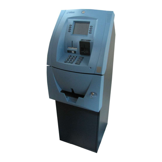
- Page 2 is guide covers upgrading the 9100 ATM to a T10 EPP. is guide applies to all service personnel involved in installing, converting, or upgrading hardware on Triton ATMs nationwide and abroad. is guide provides information, methods and easy to follow instructions for upgrading to the T10 EPP.
- Page 3 . ................ . .............. . .............. . .......... . ( ) ...... . ................. TDN 07103-00257 Rev C Triton Systems ©...
- Page 4 PLCC R E /” S C S T C U , -. / . TDN 07103-00257 Rev C Triton Systems ©...
- Page 5 9100 ATMs that have a shorter cable that won’t reach to the T10 Translator circuit board when installed on the new control panel. TDN 07103-00257 Rev C Triton Systems ©...
- Page 6 R P B TDN 07103-00257 Rev C Triton Systems ©...
- Page 7 Screen key at cables Headphone board, at cable Card Reader, Card Reader Cable, Screws P SPED SPED mounting screws Flat headphone bracket Headphone bracket mounting screws Cable routing clips TDN 07103-00257 Rev C Triton Systems ©...
- Page 8 11-13.4 in-lbs on the electric screwdriver for all the screws. CAUTION: Observe proper Electrostatic Discharge (ESD) protection when handling electronic devices. WARNING: Be careful removing and installing the control panel hinges. Improper grounding may cause damage to ATM components TDN 07103-00257 Rev C Triton Systems ©...
- Page 9 . **NOTE** is manual contains Triton’s recommended steps to covert 9100 to work with the T10. roughout this document, directions (such as le and right) are referenced with the user facing the front of the ATM.
- Page 10 1.4—Unplug the printer power cable, YELLOW circle, from the printer controller board. Ensure that no other cables are attached from the back of the cabinet to the control panel. (Ex: phone cable, dispenser cable, etc.) TDN 07103-00257 Rev C Triton Systems ©...
- Page 11 1.6—Remove the old control panel from the cabinet by partially closing the panel until it’s in a vertical position, then li panel off the cabinet as shown in image below. Place the old control panel on a at surface. TDN 07103-00257 Rev C Triton Systems ©...
- Page 12 1.7—Place the new control panel assembly (with T10 EPP) on a clean, at surface to prevent scratching, next to the old control panel. R P B TDN 07103-00257 Rev C Triton Systems ©...
- Page 13 Image 1. Remove the large nut with a 7/8” deep socket, Images 2 and 3. Remove the lock and carefully keep it in the same position as before removal, Image 4. TDN 07103-00257 Rev C Triton Systems ©...
- Page 14 2.4—Place the lock pawl in locked position, Le Image, onto the lock body. Insert the retainer screw in the lock cam and tighten, Right Image. Use a torque between 22-30 in. lbs for the electric screwdriver. Lock shown in correct position in 3rd image below. TDN 07103-00257 Rev C Triton Systems ©...
- Page 15 3.1—Remove the 4 screws from the le hinge of the old panel. Install the hinge onto the new control panel as shown in the image sequence 1-4, bottom 4 images. Old Panel Disassembled Hinge New Panel and Hinge Assembly TDN 07103-00257 Rev C Triton Systems ©...
- Page 16 2 of 4 screws, Image 3. e remaining 2 screws will be used to install the headphone bracket in the next step. NOTE: Use the images 1-4 in step 3.1 as reference for installing the right hinge. TDN 07103-00257 Rev C Triton Systems ©...
- Page 17 Open metal clip and remove at cable, but do not unplug from headphone board. 4.2—Le Image, remove two screws that hold the headphone board to the control panel, circles. Discard these two screws. Remove Headphone board/bracket/cable from the control panel, Right Image. TDN 07103-00257 Rev C Triton Systems ©...
- Page 18 4.4—Position the headphone board on the new Headphone circuit board retaining bracket, kit Item 2, under the angled bend. Loosely attach headphone board to bracket using two screws, circles, and two nuts removed from step 4.3. e screws will be tightened in a later step. TDN 07103-00257 Rev C Triton Systems ©...
- Page 19 4.7—Fold the at cable twice into the clip, but leave a 1.5 inch pigtail pass the clip, and close tabs over the cable. Note: Do not crease cable to prevent damage. TDN 07103-00257 Rev C Triton Systems ©...
- Page 20 5.2—Right Image, unplug the printer low-paper sensor cable, YELLOW circle, from the mainboard. Open metal clip tabs holding the at low-paper sensor cable. 5.3—Loosen the thumb screw until the springs pushes it out as shown below. TDN 07103-00257 Rev C Triton Systems ©...
- Page 21 9100 ATMs may not contain the ground cable. Right Image, Set the printer sub-assembly aside for later re-installment. 5.5—Le Image, remove the 4 screws, circle, on the paper chute. Right Image, Set the chute and screws aside for later re-installment. TDN 07103-00257 Rev C Triton Systems ©...
- Page 22 . 6.1—Unplug the card reader communications cable from the mainboard as shown below. 6.2—Remove Card Reader and screws, circles and set aside for later re-installation. TDN 07103-00257 Rev C Triton Systems ©...
- Page 23 . 7.1—Unplug All cables from both ends of the mainboard. TDN 07103-00257 Rev C Triton Systems ©...
- Page 24 7.2—Remove and save the 3 screws, YELLOW circles, attaching the mainboard assembly housing. Remove mainboard assembly housing and set aside for later re-install. TDN 07103-00257 Rev C Triton Systems ©...
- Page 25 Set the display aside for later re-install. 8.2—Remove the display gasket from the old control panel, YELLOW arrows and re-install it onto the new panel. Old panel New Panel TDN 07103-00257 Rev C Triton Systems ©...
- Page 26 e at screen key cable included in the kit may be used for the le side if the old at cable is too short. Le Right 9.2—Remove the 2 screws securing the le screen key assembly and install onto the new control panel. Repeat this process for the right screen keyboard. TDN 07103-00257 Rev C Triton Systems ©...
- Page 27 10.1—Remove the 2 screws, circles, from the speaker bracket in the old panel. Move speaker and bracket to new panel and secure with same screws removed from old panel, arrow and circle. Old Panel New Panel TDN 07103-00257 Rev C Triton Systems ©...
- Page 28 18.3. 11.3—Continue routing the le -side at screen key cable through the clips, YELLOW circles, and close the 2 side tabs as pictured below. TDN 07103-00257 Rev C Triton Systems ©...
- Page 29 T10 translator mounting bracket, kit Item 3, T10 translator board, kit Item 1, and four mounting screws, kit Item 6. 12.2—Remove the two screws from the mainboard housing and remove the cover. TDN 07103-00257 Rev C Triton Systems ©...
- Page 30 EPROM chip is located in the at corner of the socket when inserted. 12.5—Close the mainboard housing and secure it with a screw on the bottom side only. e top screw will be installed when the new bracket is installed. TDN 07103-00257 Rev C Triton Systems ©...
- Page 31 13.2—Place the T10 translator board, kit Item 1, on the standoff s as shown in Le Image. Obtain four screws, kit Item 6, to secure the board to the standoff s, YELLOW circles, Right Image. TDN 07103-00257 Rev C Triton Systems ©...
-
Page 32: Main Board
Observe proper Electrostatic Discharge (ESD) protection when handling electronic devices. 13.3—Plug the SPED communications cable from the old control panel into the T10 Translator Board and Mainboard, circles. Note: this was connected to the keypad. Translator Board Mainboard TDN 07103-00257 Rev C Triton Systems ©... - Page 33 T10 translator board. Note that the blue tab on the cable should be facing away from the mainboard. 14.4—Right Image, plug the display cable, inverter cable and the speaker cable into the mainboard. TDN 07103-00257 Rev C Triton Systems ©...
- Page 34 Secure the card reader in place using 4 screws, YELLOW circles, removed from card reader in step 6.2. You will need a long sha Phillips screwdriver for these screws. R P B TDN 07103-00257 Rev C Triton Systems ©...
- Page 35 e le and right locking tabs will close as the cable is inserted into the port. Ensure the tabs click into the locking position. 15.3—Plug the card reader cable into port J2, rectangle, in the back of the Mainboard. TDN 07103-00257 Rev C Triton Systems ©...
- Page 36 16.3—Le Image, place the ground wire lug over the 4th opening and secure with a screw. Fold the printer head down, arrow. Right Image, secure printer head by tightening the thumb-screw, YELLOW circle. TDN 07103-00257 Rev C Triton Systems ©...
- Page 37 YELLOW dashes and through the metal clips, YELLOW circles. Close the clips to secure the cable. Plug Low Paper Sensor at cable, blue side faces in, and the Printer cable into the mainboard. TDN 07103-00257 Rev C Triton Systems ©...
- Page 38 Item 11, for the T10 EPP, Le Image, into the EPP connector, and the T10 translator board connector, BLUE circle Right Image. 16.7—Plug T10 EPP communications cable, RJ45-RJ45 circles, kit Item 10, into the EPP and the T10 translator board connector, YELLOW circles. TDN 07103-00257 Rev C Triton Systems ©...
- Page 39 Press right hinge down and hook tab into cabinet rectangle, Le Image. While holding the hinge, insert one screw and tighten, circle, to hold bracket to cabinet, Right Image. 17.2—Repeat step 17.1, starting with second sentence for the Le Hinge. TDN 07103-00257 Rev C Triton Systems ©...
- Page 40 18.1—Le Image, use the screws from step 1.2 to secure the ground wire lug from the power supply to the display bracket. Right Image, secure the ground wires from the card reader and control panel to the printer chute. 18.2—Plug the printer power cable into the printer controller board. TDN 07103-00257 Rev C Triton Systems ©...
- Page 41 18.3— Plug the Input Power cable into the Mainboard. Plug EJ/Dispenser Cable and Phone Cable into the mainboard. 18.6—Secure all cables in place with 6” Ty-Wraps, arrows. TDN 07103-00257 Rev C Triton Systems ©...
- Page 42 Close-up view using 6” Ty-Wraps. Secure cables to the headphone mounting bracket with 8” Ty-Wrap and secure cable two inches further down the cable, as shown below, with a 6” Ty-Wrap. TDN 07103-00257 Rev C Triton Systems ©...
- Page 43 18.8—Le Image, replace the paper roll, YELLOW circles. Right Image, plug external AC power cord, YELLOW circles into socket next to the fuse. Press ON(I) on the switch to power unit up. TDN 07103-00257 Rev C Triton Systems ©...
- Page 44 . ( ) 19.1—Plug the at headphone cable into the mainboard. Note the position of the blue tab for proper installation. TDN 07103-00257 Rev C Triton Systems ©...
- Page 45 • TriComm 2.1.24 User Manual or 7.4F so ware release notes. • Laptop/PC with serial port connection. If no serial port exits, a USB Serial Port Adapter is required. Triton Part# 01260-00019. • Any USB to Serial Port Adapter may work if drivers are installed.
Need help?
Do you have a question about the T10 EPP 9100 and is the answer not in the manual?
Questions and answers