
Subscribe to Our Youtube Channel
Related Manuals for Noraxon Ultium 808


Summary of Contents for Noraxon Ultium 808
- Page 1 2D Goniometer SmartLead User Manual Ultium ™ Biomechanics Research System 2D Goniometer SmartLead User Manual (Rev D January 2020)
-
Page 2: Table Of Contents
2D Goniometer SmartLead User Manual Table of Contents Introduction............................5 Brief Description ........................5 Contradictions.......................... 5 Definitions............................6 Graphic Symbols and Meaning ....................6 Glossary of Terms ........................6 Identification ............................. 7 Model Designation ........................7 Product Versions and Configurations ..................7 General Warnings and Cautions ...................... - Page 3 2D Goniometer SmartLead User Manual Troubleshooting ......................... 21 10.1 Website Link to FAQ ......................21 Service and Repair ........................22 11.1 Warranty Information ......................22 11.2 Submitting Technical Support Requests ................22 11.3 Returning Equipment ......................22 Spare Parts and Consumables ....................23 12.1 Consumable Items.........................
- Page 4 Noraxon and myoRESEARCH are registered trademarks and the Noraxon logo, myoANALOG, myoFORCE, myoMETRICS, myoMOTION, myoMUSCLE, myoPRESSURE, myoVIDEO, myoSYNC, NiNOX, TRUsync and Ultium are common-law trademarks of Noraxon U.S.A., Inc. All other trademarks are the property of their respective owners. ©2018, all rights reserved.
-
Page 5: Introduction
The 2D Goniometer SmartLead is an accessory to the Ultium EMG sensor (#810) that allows the user to measure and quantify angles (such as joint angles, spine flexion, etc.) during physical activity either separately or in combination with other physiological signals using the Noraxon Ultium EMG system. -
Page 6: Definitions
2D Goniometer SmartLead User Manual 2 Definitions 2.1 Graphic Symbols and Meaning The following international icons and symbols may be found on the 2D Goniometer SmartLead enclosures and in this user manual. Their meaning is described below. Read material in the Instruction Manual wherever this symbol appears. -
Page 7: Identification
Sensor (Part #810) and the Ultium Receiver (Part #880). For additional equipment details refer to Section 9 of this manual. As the Noraxon Systems require software to perform its function, the equipment is offered in combination with the following computer program packages:... -
Page 8: General Warnings And Cautions
2D Goniometer SmartLead User Manual 4 General Warnings and Cautions 4.1 Risks and Benefits There is no identified risk of physical harm or injury with use of the 2D Goniometer SmartLead. The benefit provided by use of the SmartLead is that it provides users with the freedom to select the appropriate sensor for their application. -
Page 9: Preparing The Product For Use
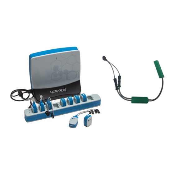
2D Goniometer SmartLead User Manual 5 Preparing the Product for Use 5.1 Unpacking and Component Identification 2D Goniometer SmartLead (Part #808) 2D Goniometer Part#: PGXY1 (SG150) PGXY2 (SG65) PGXY(Custom length) Additional contents not illustrated 2D Goniometer SmartLead User Manual (part #808A) This document 5.2 Component Inputs, Outputs, and Indicators EMG Sensor (Top) Smart Lead Connector –... -
Page 10: Component Interconnections
2D Goniometer SmartLead User Manual Serial Number – Unique 5- character serial number which identifies each EMG sensor. 2D Goniometer SmartLead Serial Number: Unique 5- character serial number which identifies each SmartLead. 5.3 Component Interconnections Step 1 Connect the 2D Goniometer SmartLead to the Ultium Designated Ultium Sensor (See ‘MR3 Configuration’... -
Page 11: Device Communication (Driver) Software Installation
MR3 software. 5.6 Companion Software Configuration Before the Footswitch can be used with the Noraxon Ultium system, the companion software must be configured to recognize the different components that make up the system. Refer to the Ultium system’s hardware manual for instructions on the software module (MR3 myoMUSCLE) supplied with... - Page 12 2D Goniometer SmartLead User Manual Step 2 Click ‘Detect Sensors in Charger’ (All sensors which you would like to use must be in the charger) – this will add the SmartLead(s) to the list of sensors (only if the unique SmartLead is connected to their corresponding sensor).
- Page 13 Goniometer 1 Y). Step 5 Continue with the measurement setup as described in the Noraxon Ultium system’s hardware manual. 5.6.2 Find My Sensor Feature Find my Sensor allows the user to quickly locate a specified Ultium sensor while creating/editing a MR3 configuration (refer to section 7 for guidance on how to create or edit a configuration).
- Page 14 2D Goniometer SmartLead User Manual (Rev D January 2020)
-
Page 15: Pre-Use Check
2D Goniometer SmartLead User Manual 6 Pre-Use Check 6.1 Normal Appearance of Signals The sensor’s STATUS LED provides a means of communicating its operational state. In the idle state, the STATUS LED will flash blue at a low, once per second rate. When the sensor is actively measuring a signal, the STATUS LED will flash recognizably faster (green). -
Page 16: Operating Instructions
Never use the Noraxon Ultium System on a person with an implanted pacemaker • Never operate the Noraxon Ultium System within 1 meter of any critical medical device 7.2 Normal Functions with Interface to a PC When used with the companion software, the 2D Goniometer SmartLead displays and records signals in degrees. - Page 17 2D Goniometer SmartLead User Manual individually and carefully making sure that the minimum permissible bend radius is observed, particularly where the measuring element enters the endblocks. When cleaning or disinfecting goniometers, remove them from the Ultium SmartLead to prevent liquid from leaking into the Ultium SmartLead and Sensor. When using SG series sensors, care should be taken during mounting so that the measuring element always forms a “simple”...
-
Page 18: Goniometer Maintenance
2D Goniometer SmartLead User Manual 7.7 Goniometer Maintenance The sensors contain no user serviceable components. In the event of malfunction, the sensor should be returned to the supplier, accompanied by a description of what has been observed and what instrumentation was in use. No periodic maintenance is required to ensure the correct functioning of the sensors. -
Page 19: Cleaning
The 2D Goniometer SmartLead is not warranted against exposure to any of the conventional forms of sterilization(autoclave, heating, etc.). Users wishing to utilize this equipment in a sterile environment, such as an operating theater, should consult Noraxon for other options. When cleaning or disinfecting, the sensors must be disconnected from all instrumentation. -
Page 20: Maintenance
9.3 Companion Software Updates • Perform a backup of the data folders to a separate drive as a precaution. • Click on the Patch/Update link provided in the email or as given on the Noraxon website. • Download the Patch/Update file. •... -
Page 21: Troubleshooting
MR3 and run a firmware update if needed. 10.1 Website Link to FAQ Answers to common questions can be found at Noraxon’s Frequently Asked Questions (FAQ) website page at this link: https://www.noraxon.com/support-learn/technical-support/faqs/ Other educational material is available at this link: https://www.noraxon.com/support-learn/technical-support/... -
Page 22: Service And Repair
If you are shipping from outside the USA please use UPS, FedEx, DHL, or EMS (US Postal Service) and not a freight-forwarder. Using a freight-forwarder incurs additional brokerage fees. If a package is shipped to Noraxon via a carrier other than the ones listed above, it may be refused. 12 Spare Parts and Consumables 12.1 Consumable Items... - Page 23 2D Goniometer SmartLead User Manual Part Image Description FSR1 Inline Footswitch FSR Sensor 085F_ Foot Insole Elastic strap, 36 inches long (cut to length) for securing Ultium sensors (Rev D January 2020)
-
Page 24: Specifications Of The Product
2D Goniometer SmartLead User Manual 13 Specifications of the Product 13.1 Expected Useful Lifetime The Ultium 2D Goniometer SmartLead has a usable life of seven years. 13.2 Technical Specifications Measurement Axes: 2 (X/Y) Sample Rate: 500/1000Hz Nominal Input Range: +/- 150 degrees Resolution: 0.006 degrees Analog Output scale factor: 25mV/degree Accuracy: +/- 2 degrees... -
Page 25: Appendix A: Goniometer Specifications
2D Goniometer SmartLead User Manual 14 Appendix A: Goniometer Specifications (Refer to figure above) SG65 SG75 SG110 SG110/ SG150 SG150/B Q110 Q150 Number of Channels Dimensions mm A. Maximum A. Minimum Weight (g) Minimum permissible bend rad. (mm) 150 150 150... -
Page 26: Electrical Goniometer Theory
2D Goniometer SmartLead User Manual In general, there are no fixed rules governing which size of sensor is most suitable for a particular joint; this depends on the size of the subject. The sensor must be capable of reaching across the joint so that the two endblocks can be mounted where least movement occurs between the skin and underlying skeletal structure. - Page 27 2D Goniometer SmartLead User Manual within the limits of the sliding endblock and without changing the relative angles between them, then the outputs remain constant. In certain applications, when mounting the goniometer across the joint, (for example when measuring flexion/extension of the wrist as shown in Fig. 3), the center of rotation of the sensor measuring element does not coincide with the center of rotation of the joint.
- Page 28 2D Goniometer SmartLead User Manual Fig. 2 Wrist Flexion/Extension Fig. 3 Linear Displacement POSITION 2 POSITION 1 Fig. 4 Goniometer Buckling POSITION 1 Fig. 5 (Rev D January 2020)
-
Page 29: Electrical Goniometer Sensor Application
2D Goniometer SmartLead User Manual 15.1.1 Crosstalk Crosstalk is defined as the ability of the goniometer to measure independently the simultaneous angular movements of a joint in 2 degrees of freedom. Most of the joints discussed in this manual do not have crosstalk, with the exception being the wrist and hip. - Page 30 2D Goniometer SmartLead User Manual Do not bend the sensor in the Y-Y direction more than 20 from the neutral position. This will result in reduced life or failure. The F35 sensor is designed to fit over the joint to be measured (figure 6). It has high flexibility and low operating force to ensure the instrument does not interfere with normal joint movement.
- Page 31 2D Goniometer SmartLead User Manual Oxbow” is permitted for goniometer F35 15.2.2 Wrist Start with the subject’s shoulder in abduction at 90 degrees and elbow flexed at 90 degrees, such that the forearm is close to full pronation. As shown in figure 9, attach the distal endblock to the dorsal surface over the third metacarpal with the center axis of the hand and endblock coincident.
- Page 32 2D Goniometer SmartLead User Manual Attach the distal endblock over the 3 metacarpal. Fully flex wrist, extend goniometer to position 2, then attach proximal endblock to the forearm. 15.2.3 Elbow 1) Position the subject’s shoulder in abduction at 90 degrees with the elbow and forearm in neutral position.
- Page 33 2D Goniometer SmartLead User Manual Goniometer placement for elbow flexion/extension. 15.2.4 Ankle Goniometer SG 110/A 1) Have the subject stand in a neutral position with the foot on a flat surface. 2) Attach the fixed endblock of the SG110/A to the side of the foot as shown in figure 13. 3) Invert the ankle to the maximum anticipated during measurement.
- Page 34 2D Goniometer SmartLead User Manual Ankle placement using SG 110 Green plug: measures inversion/eversion Gray plug: measures Dorsi flexion/plantar flexion 15.2.5 Knee 1) Have the subject stand in the neutral position with the foot on a flat surface. 2) Attach the distal endblock laterally on the leg so the axes of the leg and endblock coincide, when viewed in the sagittal plane (figure 15).
- Page 35 2D Goniometer SmartLead User Manual Hip placement Green plug: measures flexion/extension Gray plug: measures abduction/adduction 15.2.7 Back 1) Attach the proximal endblock to the sacral area at S1 as shown in figure 17. 2) With the patient upright and the goniometer near minimum length, attach the sliding endblock to the back at T12-L1 (this will vary depending upon patient height).
- Page 36 2D Goniometer SmartLead User Manual Single Axis Torsiometer (Q Series) Forearm Placement for Pronation/Supination using a Torsiometer. (Rev D January 2020)
-
Page 37: Sign Conventions For Selected Joints
2D Goniometer SmartLead User Manual 15.3 Sign Conventions for Selected Joints The sign convention for certain joints will differ depending which side of the body the sensor is attached to. Sign conventions for the most common joints are shown below and following pages. 15.3.1 Finger, Wrist and Elbow (Rev D January 2020) - Page 38 2D Goniometer SmartLead User Manual 15.3.2 Knee and Hip (Rev D January 2020)
- Page 39 2D Goniometer SmartLead User Manual 15.3.3 Ankle and Back (Rev D January 2020)
Need help?
Do you have a question about the Ultium 808 and is the answer not in the manual?
Questions and answers