Table of Contents
Advertisement
Quick Links
Advertisement
Table of Contents

Related Manuals for Noraxon DTS BioMonitor 552


Summary of Contents for Noraxon DTS BioMonitor 552
- Page 1 DTS BioMonitor User Manual Model 552 BioMonitor User Manual P-5528 Rev F...
-
Page 2: Authorized European Representative
Noraxon and myoRESEARCH are registered trademarks and the Noraxon logo, myoANALOG, myoFORCE, myoMETRICS, myoMOTION, myoMUSCLE, myoPRESSURE, myoVIDEO, myoSYNC, NiNOX, TRUsync and Ultium are common-law trademarks of Noraxon U.S.A., Inc. All other trademarks are the property of their respective owners. ©2018, all rights reserved. -
Page 3: Table Of Contents
DTS BioMonitor User Manual Table of Contents Section 1: Introduction Brief Description..........................5 Intended Use..........................5 Contraindications .......................... 5 Section 2: Definitions Graphic Symbols and Meaning ....................6 Glossary of Terms ........................6 Section 3: Identification Model Designation ........................7 Product Versions and Configurations ................... - Page 4 DTS BioMonitor User Manual Section 10: Cleaning Safety Precautions When Cleaning .................... 13 Cleaning by Users ........................13 Section 11: Maintenance Safety Precautions When Performing Maintenance..............14 Maintenance by Users ........................ 14 Charging the DTS Sensors ..................... 14 Maintenance by Qualified Individuals ..................15 Companion Software Updates ....................
- Page 5 DTS BioMonitor User Manual Section 18: Appendices Appendix A – Interference Between WiFi and DTS Radio Frequency Channels ...... 21 Instructions to change the RF channel: .................. 21 Appendix B – Sensor RF Channel Frequencies................. 22 Appendix C – Radiation Exposure Information Regarding Use of the BioMonitor ..... 23 Appendix D –...
-
Page 6: Section 1: Introduction
The BioMonitor produces six simultaneous real-time data streams including ECG, heart rate, R-R intervals, thoracic impedance, respiration rate and body skin temperature. This sensor can work with any of the Noraxon DTS receivers. This direct transmission concept greatly simplifies the arrangement of EMG and other measurements by eliminating cable connections between the electrodes and amplifier. -
Page 7: Section 2: Definitions
DTS BioMonitor User Manual Section 2: Definitions Graphic Symbols and Meaning The following international icons and symbols are found on the BioMonitor enclosure and in this user manual. Their meaning is described below. Read material in the Instruction Manual wherever this symbol appears. -
Page 8: Section 3: Identification
Model 552 BioMonitor Product Versions and Configurations The model 552 BioMonitor can work in conjunction with any of the Noraxon DTS systems. As the BioMonitor requires software to perform its function, the equipment is offered in combination with the following computer program packages. -
Page 9: Section 4: General Warnings And Cautions
DTS BioMonitor User Manual Section 4: General Warnings and Cautions Risks and Benefits There is no identified risk of physical harm or injury with use of BioMonitor product. The benefit provided by use of the device is the provision of objective measures to assess the severity of pathological human movement conditions and gauge any subsequent improvement offered by therapy, training, prosthetic alterations or ergonomic design changes. -
Page 10: Section 5: Getting Started
Please see the hardware manual for the appropriate DTS Receiver. Companion Software Installation The BioMonitor is compatible with several different DTS receivers that use the Noraxon MR3 myoMUSCLE software program. For software installation, follow the instructions given in the DTS Receiver hardware manual. -
Page 11: Companion Software Configuration
DTS BioMonitor User Manual Companion Software Configuration Before the BioMonitor can be used with the DTS system, the companion software must be configured to recognize the different components that make up the system. Refer to the DTS Receiver hardware manual for instructions for the particular program (MR3 myoMUSCLE) supplied with the DTS. -
Page 12: Section 8: Operating Instructions
DTS BioMonitor User Manual Section 8: Operating Instructions Safety Information Summary Strictly follow all safety practices given in section 3 of this manual. The most critical ones are repeated here. CAUTIONS • Never use the Biomonitor on a person with an implanted pacemaker •... -
Page 13: Exceptional Functions/Situations (Error Messages)
Description More… 542C Double sided tape for attaching DTS sensors, 504 per package As new accessories may be available after the time of printing, please check Noraxon’s website at this link for the latest offerings. http://noraxon.com/products Options Part No. Image Description More…... -
Page 14: Section 10: Cleaning
DTS BioMonitor User Manual Section 10: Cleaning Safety Precautions When Cleaning WARNING Only use a damp cloth with mild soap and water or isopropyl alcohol to clean the bottom of the BioMonitor. Do not immerse Biomonitor in any water or liquid. Cleaning by Users Clean the bottom of the EMG Sensors on a regular basis. -
Page 15: Section 11: Maintenance
DTS BioMonitor User Manual Section 11: Maintenance Safety Precautions When Performing Maintenance No precautions required. Maintenance by Users Because the DTS sensor batteries are Li-Ion, the only battery maintenance required is recharging. Charging the DTS Sensors The DTS Sensors may be charged using the DTS Sensor Charging Station •... -
Page 16: Maintenance By Qualified Individuals
Companion Software Updates • Perform a backup of the data folders to a separate drive as a precaution. • Click on the Patch/Update link provided in the email or as given on the Noraxon website http://www.noraxon.com/support/downloads/ • Download the Patch/Update file. -
Page 17: Section 12: Trouble Shooting, Fault Diagnosis
(esp. at long distances) of-sight relationship between sensor and receiver Website Link to FAQ Answers to common questions can be found at Noraxon’s Frequently Asked Questions (FAQ) website page at this link: http://noraxon.com/faq Other educational material is available at this link: http://www.noraxon.com/biomechanics-measurement-solutions/educational-material/books-... -
Page 18: Section 13: Service And Repair
If you are shipping from outside the USA please use UPS, FedEx, DHL, or EMS (US Postal Service) and not a freight-forwarder. Using a freight-forwarder incurs additional brokerage fees. If a package is shipped to Noraxon via a carrier other than the ones listed above, it may be refused. -
Page 19: Section 14: Spare Parts And Consumables
DTS BioMonitor User Manual Section 14: Spare Parts and Consumables Consumable Items Part Image Description 542C Double sided tape for attaching DTS sensors, 504 per package Section 15: Taking Product out of Operation Disposal of Equipment The BioMonitor contains a Li-Polymer battery, which may be hazardous if disposed of incorrectly. Please check with the governing authorities in your location before disposing of the BioMonitor. -
Page 20: Section 16: Specifications Of The Product
DTS BioMonitor User Manual Section 16: Specifications of the Product Expected Useful Lifetime The BioMonitor has a usable life of seven years. The BioMonitor operates with a rechargeable Lithium Ion battery. The battery capacity will decline with ongoing use and require replacement after 500+ discharge/charge cycles to preserve the device’s rated 8 hours of operating time. -
Page 21: Section 17: Technical Information
DTS BioMonitor User Manual Section 17: Technical Information Block Diagram Model 552 DTS BioMonitor Coming Soon… Theory of Operation The DTS wireless systems are based on a pre-certified transceiver module. This radio module operates in the 2.4 GHz bands with an output power level of 1 mW and is based on a Wireless USB product by Cypress Semiconductor. -
Page 22: Section 18: Appendices
Use a network sniffer program to determine which WiFi RF channels are being used in your area. InSSIDer” is a network sniffer with a graphical display that is available as a free download from the Noraxon website at: http://www.noraxon.com/docs/default-source/Utility-Downloads/noraxon-inssider2- installer.zip?sfvrsn=0 This network sniffer is compatible with Windows XP, Vista and 7 (32 and 64-bit). -
Page 23: Appendix B - Sensor Rf Channel Frequencies
DTS BioMonitor User Manual Appendix B – Sensor RF Channel Frequencies The BioMonitor operates on a RF channel. The RF Channels (A-H) are assigned to the RF frequencies according to the table below. RF Channel Frequency (GHz) 2.400-2.409 2.415-2.424 2.427-2.436 2.439-2.448 2.451-2.460 2.463-2.472... -
Page 24: Appendix C - Radiation Exposure Information Regarding Use Of The Biomonitor
(next to the person’s head). At present, Noraxon identifies no restrictions on use and placement of the DTS sensors on any portion of the human body. The DTS sensors operate at radio frequencies known to effect older style pacemakers. -
Page 25: Appendix D - Radio Regulatory Statements
DTS BioMonitor User Manual Appendix D – Radio Regulatory Statements FCC Statement This device complies with part 15 of the FCC rules. Operation is subject to the following two conditions: (1) This device may not cause harmful interference, and (2) this device must accept any interference received, including interference that may cause undesired operation. -
Page 26: Appendix E - Biomonitor Electrode Placement
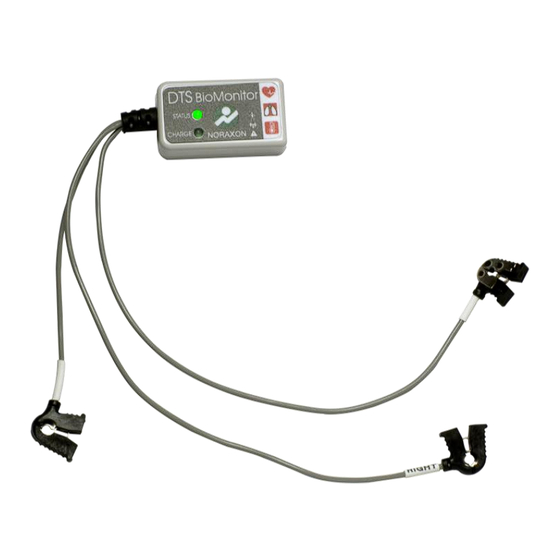
DTS BioMonitor User Manual Appendix E – BioMonitor Electrode Placement The biomonitor is a sensor designed to simultaneously capture heart rate, respiration and temperature. To capture this data, three single electrodes are required and may be placed in three different location patterns, based on the data the user wished to capture. Each placement utilizes the LEFT lead, RIGHT lead and Right Leg Driver (RLD).
Need help?
Do you have a question about the DTS BioMonitor 552 and is the answer not in the manual?
Questions and answers