Table of Contents
Advertisement
Quick Links
Advertisement
Table of Contents

Related Manuals for CAME ZL22N


Summary of Contents for CAME ZL22N
- Page 1 CONTROL PANEL FA00993-EN FOR 24 V GEARMOTORS ZL22N INSTALLATION MANUAL EN English...
- Page 2 GENERAL PRECAUTIONS FOR INSTALLERS ⚠ Important safety instructions. ⚠ Follow all of these instructions. Improper installation can cause serious bodily harm. Use this product only for its specifically intended use. Any other use is hazardous. • The manufacturer cannot be held liable for any damage caused by improper, unreasonable, and erroneous use.
- Page 3 with the harmonized standards and the essential requisites of Machinery Directive 2006/42/CE. • Any residual risks must be indicated clearly with proper signage affixed in visible areas. All of which must be explained to end users. • Fit, in plain sight, the machine's ID plate when the installation is complete.
-
Page 4: Technical Data
Multiple controls: a type of opening or closing control for multiple operators (from a minimum of 2 to a maximum of 4 at the same time). With the ZL22N and LM22N control panel the multiple control can only be wired (button, selector, etc.). All connections and links are rapid-fuse protected. -
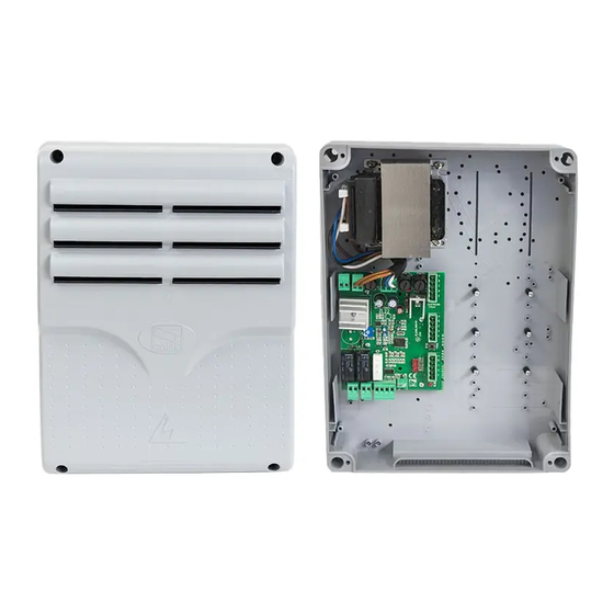
Page 5: Description Of Parts
14 - Voltage present warning LED 6 - Button for programming 15 - Power supply terminal board 7 - Terminal board for connecting the accessories 8 - Terminal board for connecting the gearmotor 9 - Terminal board for connecting control and safety devices ZL22N... - Page 6 GENERAL INSTALLATION INDICATIONS ⚠ Before working on the control panel, cut off the mains power supply and remove any batteries. Cable types and minimum thicknesses cable length Connection < 20 m 20 < 30 m Control board power supply 230 V AC (1P+N) 2G x 1.5 mm 2G x 2.5 mm Gearmotor 24 V AC...
- Page 7 ❹ Assemble the pressure hinges. ❺ Fit the hinges into the box (either on the right or left) and fasten them using the supplied screws and washers. ❻ Snap the cover onto the hinges. Close it and secure it using the supplied screws. ❼...
- Page 8 2 - Accessories 24 V AC - max 25 W power-supply output 3 - Control board power-supply input Radio control 4 - AF board 5 - RG58 cable of the antenna Gearmotors 6 - Connection to UNIPARK 230V ZL22N ...
-
Page 9: Operating Modes
Operating modes Mode 1 (default): 2-7 (NO) OPEN-CLOSE and 2-1 (NC) STOP. Mode 2: 2-7 (NO) OPEN and 2-1 (NO) CLOSE (recommended for multiple commands). Operating mode change Switch on the board pressing and holding down the programming button for 10 seconds: - from mode 1 to mode 2, the red LED flashes twice;... - Page 10 Safety devices Photocells Input for photocells or magnetic loop. Reopening during closing. When the barrier is closing, opening the contact causes the movement to invert until the barrier is fully open. ZL22 If the safety device is not used, short-circuit the input 2 - C1. 24V 15V 0V 10 11 10 11...
- Page 11 24V 15V 0V ADJUSTMENTS AND FUNCTIONS Amperometric sensor sensitivity adjustment Amperometric sensor sensitivity adjustment ⚠ The motor current consumption is proportional to the parking saver power. FUSIBILE FUSIBILE FUSIBILE LINEA 5A ACCS. CENTRALINA 315 mA 3,15 A-F FUSIBILE FUSIBILE FUSIBILE LINEA 5A ACCS.
-
Page 12: Preliminary Operations
MANAGING USERS BY AN ASSOCIATED RADIO CONTROL Preliminary operations Check that the RG58 cable of the antenna is connected to the appropriate terminals, and that AF board is inserted on the electronic board connector. Before fitting the AF board, you MUST CUT OFF THE MAIN POWER SUPPLY and, remove any emergency batteries. -
Page 13: Deleting A Single User
Deleting a single user Set DIP-switch 4 to ON. Keep pressed the PROG button on the control board. The programming LED flashes. Within five seconds, press the button on the transmitter of the user you wish to delete. The LED will flash quickly for one second to signal that the user has been deleted, and then it will switch off. - Page 14 FINAL OPERATIONS Fastening the cover Once finished with the electrical connections and powering up, fit the cover and secure it using the supplied screws. DISMANTLING AND DISPOSAL Always make sure you comply with local laws before dismantling and disposing of the product. The packaging materials (cardboard, plastic, and so on) should be disposed of as solid household waste, and simply separated from other waste for recycling.
- Page 16 CAME S.p.A. Via Martiri Della Libertà, 15 31030 Dosson di Casier - Treviso - Italy tel. (+39) 0422 4940 - fax. (+39) 0422 4941...
Need help?
Do you have a question about the ZL22N and is the answer not in the manual?
Questions and answers