Table of Contents
Advertisement
Available languages
Available languages
Quick Links
SERVICE MANUAL
PX1304 POGO
PUMP ASSEMBLIES
Theoretical Output @ 60 cycles/min:
Maximum recommended continuous cycle rate:
Maximum recommended intermittent cycle rate:
77-3040-R1.2 (10/2014)
SPECIFICATIONS
Ratio:
Maximum air inlet pressure:
Maximum fluid pressure:
Displacement per cycle:
Maximum operating temperature:
Piston diameter:
Nominal motor stroke:
Air inlet connection:
Outlet size:
Weight:
PX1304-5
72.5 psi [5 bar]
290 psi [20 bar]
2.7 oz [81 CC]
1.3 gpm [4.9 l/m]
20 cycles/min. [40 strokes]
40 cycles/min. [60 strokes]
160°F [71° C]
3.3 in (85 mm)
3 in [75 mm]
3/8" NPS / BSPP (female)
1/2" NPT (female)
12.6 Lb [5.7 Kg]
1 / 12
PX1304-8
4:1
116 psi [8 bar]
500 psi [34.5 bar]
EN
Advertisement
Table of Contents

Subscribe to Our Youtube Channel
Related Manuals for Binks PX1304 POGO


Summary of Contents for Binks PX1304 POGO
- Page 1 SERVICE MANUAL PX1304 POGO PUMP ASSEMBLIES SPECIFICATIONS PX1304-5 PX1304-8 Ratio: Maximum air inlet pressure: 72.5 psi [5 bar] 116 psi [8 bar] Maximum fluid pressure: 290 psi [20 bar] 500 psi [34.5 bar] Displacement per cycle: 2.7 oz [81 CC] Theoretical Output @ 60 cycles/min: 1.3 gpm [4.9 l/m]...
- Page 2 IT IS THE RESPONSIBILITY OF THE EMPLOYER TO PROVIDE THIS INFORMATION TO THE OPERATOR OF THE EQUIPMENT. FOR FURTHER SAFETY INFORMATION REGARDING THIS EQUIPMENT, SEE THE GENERAL EQUIPMENT SAFETY BOOKLET (77-5300). Binks reserves the right to modify equipment specification without prior notice. 2 / 12...
- Page 3 4. ALWAYS remove spray tip when CAUTION minimum specifications and safety flushing the system. Operate the devices of Binks, the user assumes all Never store de-ionized, distilled, pump at the lowest possible pressure. risks and liabilities. reverse osmosis or any pure grade of water in the pump.
- Page 4 HAZARD CAUSE SAFEGUARDS EXPLOSION STATIC ELECTRICITY 1. If installing this equipment in a potentially explosive atmosphere, check the ATEX equipment category and Use of this equipment in a temperature ratings meet the requirements for the zoned potentially explosive atmosphere. area. Vapors from flammable liquids can 2.
-
Page 5: Start-Up Operation
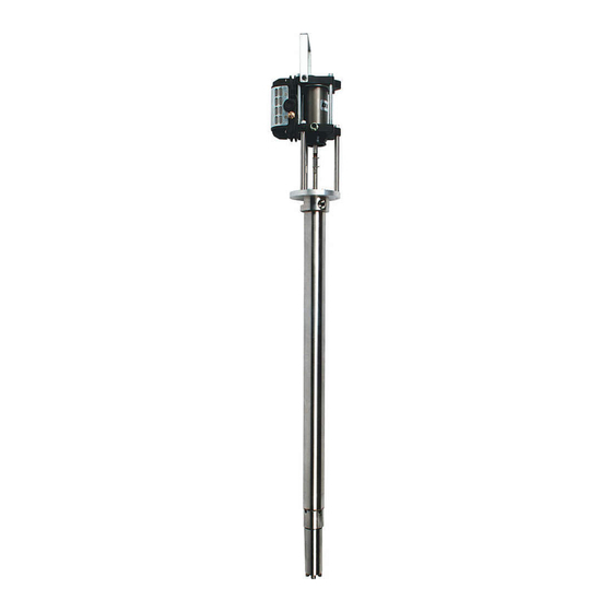
PX1304 POGO PUMP ASSEMBLIES GROUNDING THE POGO PUMP START-UP / OPERATION 1. Clamp the grounding cable to the terminal on the high 1. Prepare the POGO pump for start-up as shown above and if pressure filter or the air motor. - Page 6 PX1304 POGO PUMP ASSEMBLIES – DIMENSIONS / INSTALLATION " " 214.37mm 243mm 16 21 " Air to gun 3/8" OD tube 423.44mm Air Inlet Fluid outlet 1/4" nps 1/2" npt " 53.98mm 36 1 " 917.31mm TYPICAL DRUM INSTALLATION 41-28331...
-
Page 7: Parts List
PX1304 POGO PUMP ASSEMBLIES NOTE Please measure the overall length of item 6, Tie rod, to ensure the correct length. PARTS LIST ITEM SERVICE PART NUMBER DESCRIPTION PX1304-5P PX1304-5U PX1304-8U PX1304-8P MANUAL 0114-014351 HANDLE 0115-010272 RETAINING RING 0115-010001 SOCKET HEAD CAP SCREW... - Page 8 PFX13 FLUID PUMP DISASSEMBLY MAINTENANCE SYMBOLS: = MAINTENANCE ORDER Reverse for assembly = TORQUE VALUE in-lb or ft-lb [Nm] 75 in-lbs. [8.5 Nm] DO NOT TIGHTEN MOTOR ROD ADAPTER (7) AGAINST THE PUMP ROD OR MOTOR ROD. THREAD ON UNTIL ROD CLIP HOLES ARE ALIGNED. 8 / 12 77-3040-R1.2 (10/2014)
- Page 9 POGO PUMP ASSEMBLIES – TROUBLESHOOTING PROBLEM CAUSE SOLUTION Pump will not start No compressed air. Check compressed air supply. Spray tip is blocked. Clean or replace the spray tip. Erratic operation of Worn poppet assemblies. Replace the poppet assemblies. air motor, air motor Worn or dirty spool and sleeve Clean or replace the spool and sleeve stops...
- Page 10 POGO PUMP OUTFITS PARTS LIST ITEM SERVICE PART NUMBER DESCRIPTION 98-3062 98-3063 MANUAL 41-28272 AIR CONTROL ASSEMBLY 2101-4308-2 2100 GUN (565 X 66SS X 66SD-3) – 77-3046 2465-18CN-11S0 TROPHY GUN (1.8mm X 11C) – 77-3026 54-4976 TUBE CONNECTOR 20-3815 BUSHING, S.S. 83-2055 DM NIPPLE, S.S.
- Page 11 41-28272 AIR CONTROL ASSEMBLY PARTS LIST ITEM PART NUMBER DESCRIPTION VA-542 BALL VALVE SSP-1941-ZN STREET ELBOW, 1/4" NPT SSP-3301-NI 1/4" PIPE CROSS 20-4355-1 CLOSE NIPPLE 1/4" 59-369 PRESSURE GAUGE 0-60 85-521 PUSHLOCK SWIVEL ELBOW 3/8 OD TUBE X 1/4" NPT HAR-503-2 MINI REGULATOR 1/8"...
-
Page 12: Warranty Policy
WARRANTY POLICY Binks products are covered by Finishing Brands one year materials and workmanship limited warranty. The use of any parts or accessories, from a source other than Finishing Brands, will void all warranties. For specific warranty information please contact the closest Finishing Brands location listed below. - Page 13 MANUAL DE SERVICIO CONJUNTOS DE BOMBA POGO PX1304 ESPECIFICACIÓN PX1304-5 PX1304-5 Proporción: Presión de entrada de aire máxima: 72.5 psi [5 bar] 116 psi [8 bar] Presión máxima del fluido: 290 psi [20 bar] 500 psi [34.5 bar] Desplazamiento por ciclo: 2.7 oz [81 CC] Salida teórica @ 60 ciclos/min.: 1.3 gpm [4.9 l/m]...
- Page 14 ES RESPONSABILIDAD DEL EMPLEADOR SUMINISTRAR ESTA INFORMACIÓN AL OPERADOR DEL EQUIPO. PARA MÁS INFORMACIÓN DE SEGURIDAD ACERCA DE LOS EQUIPOS, CONSULTE EL FOLLETO DE SEGURIDAD GENERAL DE LOS EQUIPOS (77-5300). Binks se reserva el derecho a modificar las especificaciones del equipo sin previo aviso. MX-2 / 12...
- Page 15 4. SIEMPRE quite la punta con las especificaciones mínimas ni con pulverizadora al purgar el sistema. PRECAUCIÓN los dispositivos de seguridad de Binks, el Opere la bomba con la presión más usuario asume todos los riesgos y Nunca guarde en la bomba agua baja posible.
-
Page 16: Medidas Preventivas
PELIGRO CAUSA MEDIDAS PREVENTIVAS EXPLOSIÓN ELECTRICIDAD ESTÁTICA 1. Si se instala este equipo en una atmósfera potencialmente explosiva, verifique que la categoría Uso de este equipo en una ATEX (Atmósfera Explosiva) del equipo y los regímenes atmósfera potencialmente de temperatura cumplan con los requisitos para el explosiva. - Page 17 CONJUNTOS DE BOMBA POGO PX1304 CÓMO PONER A TIERRA LA BOMBA POGO INICIO / OPERACIÓN 1. Sujete el cable de puesta a tierra al terminal en el filtro de 1. Prepare la bomba POGO para ponerla en marcha como se alta presión o en el motor de aire.
- Page 18 CONJUNTOS DE BOMBA POGO PX1304 – DIMENSIONES / INSTALACIÓN " " 214.37mm 243mm 16 21 " Entrada de aire en la pistola Tubo de 3/8" DE 423.44mm Entrada de aire Salida de fluido 1/4 NPS 1/2” NPT " 53.98mm 36 1 "...
-
Page 19: Lista De Piezas
CONJUNTOS DE BOMBA POGO PX1304 NOTA Por favor, mida la longitud completa del artículo 6, barra de acoplamiento, para asegurar el largo correcto. LISTA DE PIEZAS NÚM. MANUAL NÚM. DE PIEZA DESCRIPCIÓN PX1304-5P PX1304-5U PX1304-8U PX1304-8P ART. SERVICIO 0114-014351 0115-010272 ARO DE RETENCIÓN 0115-010001 TORNILLO DE CABEZA ENCASTRADA... - Page 20 DESMONTAJE DE LA BOMBA DE FLUIDO PFX13 SÍMBOLOS DE MANTENIMIENTO: = ORDEN PARA EL MANTENIMIENTO Revertir para el montaje 75 pulg.-lbs. = VALOR DE TORSIÓN pulg-lbs o pies-lbs [Nm] [8.5 Nm] NO APRETAR EL ADAPTADOR DEL VÁSTAGO DEL MOTOR (7) CONTRA LA VARILLA DE BOMBEO O EL VÁSTAGO DEL MOTOR.
- Page 21 "POGO" CONJUNTOS DE BOMBA – LOCALIZACIÓN Y REPARACIÓN DE AVERÍAS PROBLEMA CAUSA SOLUCIÓN La bomba no arranca. Falta de aire comprimido. Revise el suministro de aire comprimido. Punta rociadora bloqueada. Limpie o cambie la punta rociadora. Operación irregular Unidades del soporte cónico Reemplace las unidades del soporte cónico.
- Page 22 EQUIPOS PARA LA BOMBA POGO LISTA DE PIEZAS MANUAL NÚM. DE NÚM. DE PIEZA DESCRIPCIÓN 98-3062 98-3063 ART. SERVICIO 41-28272 CONJUNTO DEL CONTROL DE AIRE 2101-4308-2 PISTOLA 2100 (565 X 66SS X 66SD-3) – 77-3046 2465-18CN-11S0 PISTOTA SERIE "TROPHY" (1.8 mm X 11 C) –...
- Page 23 CONJUNTO DEL CONTROL DE AIRE 41-28272 LISTA DE PIEZAS NÚM. DE NÚM. DE PIEZA DESCRIPCIÓN CANT. ART. VA-542 VÁLVULA ESFÉRICA SSP-1941-ZN CODO MACHO Y HEMBRA, 1/4" NPT SSP-3301-NI UNIÓN CRUZ, 1/4" 20-4355-1 BOQUILLA DE ROSCA CORRIDA, 1/4" 59-369 MANÓMETRO 0-60 85-521 CODO GIRATORIO DE APRIETE, TUBO 3/8"...
- Page 24 POLÍTICA DE GARANTÍAS Los productos Binks están cubiertos por la garantía limitada de materiales y mano de obra por cinco años de Finishing Brands. El uso de cualquier pieza o accesorio de una fuente que no sea Finishing Brands, anulará todas las garantías. Para obtener información específica sobre la garantía, favor ponerse en contacto con el local de Finishing Brands más cercano a usted entre los listados a continuación.
Need help?
Do you have a question about the PX1304 POGO and is the answer not in the manual?
Questions and answers