
Related Manuals for Thermo Scientific Cryofuge 5500i GMP


Summary of Contents for Thermo Scientific Cryofuge 5500i GMP
- Page 1 Thermo Scientific Cryofuge 5500i GMP Instructions for Use 20057801-e • 07 / 2020 Visit us online to register your warranty: thermofisher.com/labwarranty...
- Page 2 How to use this manual Please, use this manual to get acquainted with your centrifuge and its accessories. Overleaf you will find a graphical illustration of the control panel and a The manual helps you to avoid inappropriate handling. survey of the most important functions Make sure to always keep it close to the centrifuge.
- Page 3 acceleration deceleration display for optional temperature profiles profiles accessories speed/RCF run time program display quick run open lid key switch switch key program selection rpm-/RCF-display start stop program storage key bucket selection pre-temperature-regulation “set” keys “set” keys The mains switch is located on the right-hand side panel. Pressed up = ON Pressed down = OFF 0...
- Page 4 Keys Control panel of the Cryofuge ® 5500i GMP start : normal start of the centrifuge Displays stop : manual stop of a run Program selection open lid: open lid (possible only with the instrument Program selection key: stepwise recall of programs switched on) Switch key: open/shut program storage...
-
Page 5: Table Of Contents
Contents Contents BIOshield - Rotor ..........30 ® For your safety ........... 3 Highplate - Rotor ..........31 ® Proper use ............... 3 Handling micro plates ......... 32 Improper use ............3 Diagnostik™- Rotor ..........33 Centrifuging hazardous materials ......3 Highconic - Rotor .......... - Page 6 Contents Selecting speed ............. 50 Maintenance and care ......61 Entering the RCF value ......... 51 Maintenance to be performed by the customer ..61 RCF value explanation ........51 Cleaning ............. 61 Selecting run time ..........52 Disinfection ............62 Fixed run time ............
-
Page 7: For Your Safety
Safety instructions For your safety Proper use The centrifuge is designed to separate liquid- These centrifuges are manufactured according to suspended materials having different densities and current technical standards and regulations. Nonethe- particle size, respectively (maximum sample density is less, centrifuges may pose danger to individuals and 1.2 g/cm³... -
Page 8: Handling The Centrifuge
Safety instructions Do not centrifuge toxic or radioactive substances or You may use the centrifuge only with a properly pathogenic microorganisms without suitable safety loaded rotor. You must not overload the rotor. systems. Strictly follow the rules and regulations for cleaning If microbiological samples of risk group II (according and disinfection to “Laboratory Bio-safety Manual”... -
Page 9: Conformity To Current Standards
Safety instructions Conformity to current standards Safety instructions in this manual These centrifuges are manufactured and tested This symbol denotes potential hazards to according to the following standards and regulations: persons. - For all voltages This symbol denotes potential damage to the centrifuge or parts in its immediate IEC 61010 surroundings. - Page 10 Safety instructions CAUTION: This product is intended for General Laboratory Use. It is the customer’s responsibility to ensure that the performance of the product is suitable for customer’s specific use or application.
-
Page 11: The Cryofuge 5500I Gmp
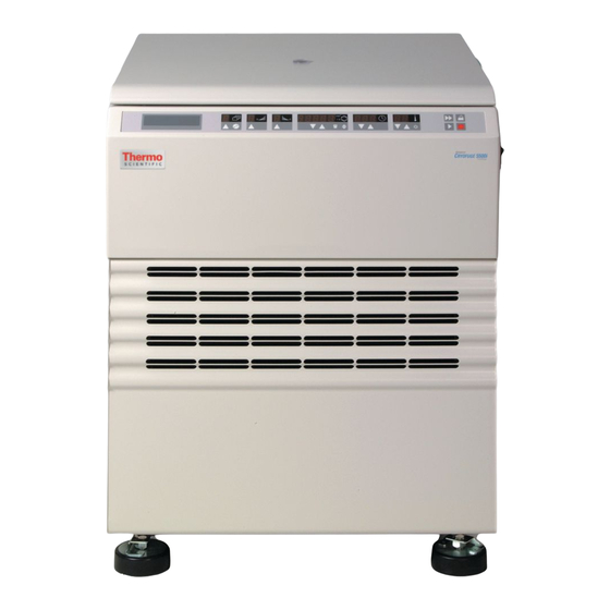
Description of the Cryofuge ® The Cryofuge ® 5500i GMP Description The figure below shows a Cryofuge 5500i GMP with ® The Cryofuge 5500i GMP is a large-scale universal ® the lid open and a LH-4000 rotor installed. centrifuge with an internal, water-cooled refrigeration system for biotechnical and pharmaceutical research, as well as for clinics and blood transfusion centers. -
Page 12: Safety Systems
Description of the Cryofuge ® Safety systems Schedule of parts supplied The Cryofuge 5500i GMP is equipped with a number Accessories supplied with the centrifuge are: ® of safety systems: connection cable Casing and lid made of 8 mm armored steel sheet. Lid with sight glass a wrench for fixing the rotor Lid lock with safety check... -
Page 13: Function And Features
Description of the Cryofuge ® Function and features Basic unit/ function Description / feature Assembly / casing galvanized steel sheet base with armored steel chamber Chamber stainless steel Drive brush less induction drive Keys and display key pad and display elements covered by an easy-care protective cover Control microprocessor controlled by “Easycontrol II”... - Page 14 Description of the Cryofuge ® The Easycontrol user interface Function Feature Program display free program selection [ - ] operating memory [ 1...9 ] memory capacity for set values “quick run”-mode Acceleration / deceleration profile 1 = slow, ... 9 = fast acceleration / deceleration curve Speed selection adjustable from 300 rpm to 10 000 rpm, in 10 rpm increments RCF selection...
- Page 15 Description of the Cryofuge ® Function Feature Lid opening automatic unlocking via “open lid” key ( (unlocking in case of power failure: see chapter “Troubleshooting”) Start start key ( Stop stop key ( “quick run” mode pressing the “quick run” key ( ) activates maximum acceleration up to the maximum permissible speed of rotor;...
- Page 16 Description of the Cryofuge ® Notes...
-
Page 17: Before The Use
Place the centrifuge, as well as ro- The setting up and connecting of the tors and accessories of plastic, so Cryofuge 5500i GMP may be imple- that they are not exposed to direct mented exclusively by trained special- solar radiation! - Page 18 Before the use Optional for HERANET Zero-potential outlet for Service inter- a water-circulation- Mains switch Mains inlet Scanner connection Water supply Water drain...
-
Page 19: Connection Conditions
Before the use Connection conditions Commissioning Before the centrifuge is connected with the mains net- Connect plug with plug socket. work, the following must be ensured: Ensure water supply and return flow. 1. A water connection is available for a ¾" screwed Activate mains switches in front to the right. - Page 20 Before the use Notes...
-
Page 21: Rotors And Accessories
Rotors and accessories Rotors and accessories A large variety of rotors are available as accessories. In addition, there are adapters and reduction sleeves for a variety of commercially available tubes and bottles. For a complete list of accessories together with tech- nical data and order numbers refer to our current sales documentation. - Page 22 Rotors and accessories Rotors and rotor buckets for Cryofuge ® 5500i GMP Table 1: Rotors Rotor designation LH-4000 4 x 1000 ml 75006475 With bucket Round bucket 1000 ml Double rectangle bucket DoubleSpin™ 2 x 250 ml Order no. 75006477 75006478 Maximum permissible load [ g ] 4 x 1400...
- Page 23 Rotors and accessories Table 1: Rotors Rotor designation LH-4000W 4 x 1000 ml 75006476 With bucket Round bucket 1000 ml Double rectangle bucket Double blood bag bucket DoubleSpin™ 2 x 250 ml Order no. 75006477 75006478 75006436 Maximum permissible load [ g ] 4 x 1400 4 x 1500 4 x 1900...
- Page 24 Rotors and accessories Table 1: Rotors Diagnostik™ Rotor Rotor designation BIOshield ® Rotor Highplate ® Rotor 4 x 250 ml 2 x 5 plates 75006480 Order no. 75006435 75006444 Maximum permissible load [ g ] 4 x 600 2 x 500 2 x 2000 Maximum speed n [ rpm ]...
- Page 25 Rotors and accessories Table 1: Rotors Highconic ® Rotor LAC-250 Rotor designation 6 x 50 ml 6 x 250 ml 75003057 75006483 Order no. Maximum permissible load [ g ] 6 x 130 6 x 400 Maximum speed n [ rpm ] 8500 10000 Maximum RCF value at n...
-
Page 26: Adapter And Accessories
Rotors and accessories Adapter and accessories Table 2: Adapter (1.1) * max. tube length with aerosol-tight cap max. tube Adapter and accessories for tubes color order no. dimensions diameter round bucket 75006477 d x length / * [ mm ] rotor Centri-Lab ®... - Page 27 Rotors and accessories Table 2: Adapter (1.2) centrifugation of order no. Accessories for blood bags in the round bucket 75006477 Plastic plug “XL” for 400 - 450 ml blood bag system (set of 2 pieces) 75006496 Plastic plug “M” for small volume special blood bank applications (set of 2 pieces) 75006485 Tare plates caoutchouc, 2 x 35 and 65 g each...
- Page 28 Rotors and accessories Table 2: Adapter (3.1) * max. tube length with aerosol-tight cap Adapter and accessories for max. tube tubes color order no. double rectangular bucket dimensions diameter 7506478 DoubleSpin™ d x length / * [ mm ] rotor Centri-Lab ®...
- Page 29 Rotors and accessories Table 2: Adapter (3.2) * max. tube length with aerosol-tight cap Adapter and accessories for max. tube tubes color order no. double rectangle bucket dimensions diameter 75006478 d x length / * [ mm ] rotor DoubleSpin™ [ mm ] (1 adapter per bucket) 24 x 15 ml conical / US-urine...
- Page 30 Rotors and accessories Table 2: Adapter (4) * max. tube length with aerosol-tight cap Adapter and accessories for max. tube tubes color order no. BIOshield ® Rotor 75006435 dimensions diameter d x length / * [ mm ] rotor Centri-Lab ®...
- Page 31 Rotors and accessories Table 2: Adapter (5) Rack max. height incl. tubes Set adapter for length / width tubes and rack per rack racks per order no. 75006480 Diagnostik™ Rotor [ mm ] [ mm ] rotor Hitachi 118 x 20 2 x 10 75006416 Olympus...
- Page 32 Rotors and accessories Table 2: Adapter (7) max. tube tubes color order no. Adapter and accessories for dimensions d x LAC-250 75006483 length [ mm ] rotor 250 ml Dry-Spin and Oak Ridge bottle 61 x 153 -— (without adapter) 1 x 250 ml PA Oak Ridge bottle 60 x 120 12002...
-
Page 33: Handling Rotors
Rotors and accessories Handling rotors LH-4000 LH-4000 W Swinging Bucket Rotors Diagnostik™ Rotor All positions must always be These rotors have a slide coating, which guarantees loaded with identical carrier perfect operation without additional lubrication of body buckets! trunnion pins for many years. The various swinging buckets are split up into weight categories. -
Page 34: Bioshield ® - Rotor
Rotors and accessories BIOshield - Rotor ® The bucket set is a permanent part of the rotor and must not be interchanged with other rotors. Do not run the rotor without the rotor lid closed. The rotor lid is opened respectively closed by pushing down and turning the lid locking knob at the same time. -
Page 35: Highplate ® - Rotor
Rotors and accessories The following examples are intended to illustrate the - Rotor Highplate ® limited service life in praxis: Do not run the rotor with the rotor lid open. Profile of use Max. service life at 5850 rpm 5350 rpm - frequent use 5 years 7 years... -
Page 36: Handling Micro Plates
Rotors and accessories Handling micro plates Highplate -Rotor ® For the loading and unloading of micro test plates remove the plate holder from the bucket. Before loading, ensure that the rubber bottom is placed in the cut-outs of the plate holder. Deep well plates can also be inserted directly into the swing without plate holder. -
Page 37: Diagnostik™- Rotor
Rotors and accessories Diagnostik™- Rotor - Rotor Highconic ® In case longer tubes shall be centrifuged precluding the complete locking of the rotor lid, it is allowed to operate the rotor The swings or carriers should always without lid, up to a maximum speed of be completely loaded with racks. - Page 38 Rotors and accessories LAC-250 Before use carefully and regularly inspect rotors made of carbon fiber composite material for surface wear. The rotor may not be operated if, due to damage, fibers escape the rotor surface! Be careful with damaged carbon fiber rotors! Never stop a running rotor manually! Sharp carbon fiber splinters can cause...
- Page 39 Rotors and accessories Temperature behavior: Procedure in case of damage: Rotors of carbon fiber composite material require In case of rotor failure wrong handling can cause significantly more time to change temperature than a dangers by the carbon fibers of the rotor. metal rotor does, since this carbon fiber composite material works like a thermal insulator.
-
Page 40: Aerosol-Tight Operation
Rotors and accessories Aerosol-tight operation For greasing the seals only use the special lubricant 76003500! When centrifuging dangerous sam- ples aerosol-tight rotors and tubes may only be opened in an approved Spare parts are delivered with the rotor or may be safety work bench! ordered separately. - Page 41 Rotors and accessories BIOshield -Rotor 75006435 Closing round buckets aerosol-tightly ® Highplate ® -Rotor 75006444 After greasing the seal, turn the lid until it fits slightly to the bucket. To achieve an uniform pre-stressing, turn the lid The aerosol-tight bio-containment of clockwise by 1 ½...
- Page 42 Rotors and accessories Closing rectangular bucket 75006478 aerosol-tightly Please flap both lock levers upwards. Now you can eas- ily put the cap on the bucket. By flapping down the lever the bucket is being locked. Both of the levers If necessary, grease the lid seal before must click, in closing.
- Page 43 Rotors and accessories Closing Highconic - Rotor aerosol-tightly ® The hexagon screwdriver of the pliers should be used as a support tool to fasten and loosen the lid of the fixed angle rotor in order to achieve secure closing (insert the hexagon through the hole in the screw cap).
-
Page 44: Checking Of Aerosol-Tight Bio-Containment
Rotors and accessories Checking of aerosol-tight bio-containment Close the bucket or rotor according to the respec- tive handling instructions. The checking of the rotor type and bucket was done Shaking the bucket releases the carbon dioxide according to the dynamic microbiological test proce- of the water, and an excessive pressure is built dure with regard to EN 61010-2-020 appendix AA. -
Page 45: Operation
Operation Operation Switching on the centrifuge Locate the mains switch on the right-hand side of the front panel. Actuating the lid For a short time, the following reading appears in the Opening the lid control panel: Press the “open lid” key If the message “Lift lid”... -
Page 46: Installing The Rotor
Operation 4. The rotor must glide freely down the collet chuck Installing the rotor until it hits the lower stop. 5. If you have installed the rotor correctly, you can Improper or improperly combined tighten the collet chuck easily using the socket accessories cause severe... -
Page 47: Loading The Rotor
Operation Loading the rotor Maximum loading If you wish to centrifuge samples that together with the adapters exceed the maximum permissible load, Overloading can result in destruc- you must either reduce the sample volume or calcu- tion and severe damage to the cen- late the permissible speed n according to the fol- trifuge! -
Page 48: Filling The Centrifuge Tubes
Operation Filling the centrifuge tubes Maximum permissible load difference The smaller the imbalance of the centri- Check carefully whether your tubes fuge the better the separation effect, be- are approved for the respective cause there are no turbulences in the RCF value. -
Page 49: Inserting The Centrifuge Tubes
Operation Inserting the centrifuge tubes Fixed-angle rotors: In extreme cases an unsymmetrical loading of the rotor could release the imbalance identification. Imbalance does not only result in noisy operation but also in a premature wear of the drive. The rotor has to be loaded symmetrically. When loading the rotor only partially, you have to ensure that opposite bore holes always receive tubes of equal weight (when centrifuging a single sample,... - Page 50 Operation Swinging bucket rotors: Improper loading For swinging bucket rotors please note the symmetrical loading of the buckets. These examples are to be applied to the other rotors in an analogous manner! Mixed loading with different bucket Proper loading types is not allowed!
- Page 51 Operation Double blood bag bucket 7500 6436: If using the double blood bag bucket only one sample shall be centrifuged attention has to be paid to merely loading the external chambers. An exclusive loading of the internal chambers could result in an overswing of the bucket.
-
Page 52: Entering Parameters
Operation Entering parameters Position B: The program memory is secured against alternations Key switch The user can use but not alternate all programs. The position of the key switch influences - The centrifugation program in the main memory the kind of operation of the “Easycontrol”- can be alternated. -
Page 53: Acceleration / Deceleration Curves
Operation Acceleration / Deceleration curves Bucket selection for swinging bucket rotors The Cryofuge 5500i GMP offers 9 acceleration and The automatic rotor identification will recognize the ® deceleration profiles for optimum centrifuging of sam- rotor cross of the swinging bucket rotor. ples with different gradients. -
Page 54: Selecting Speed
Operation for a few seconds, then changes to actual value Selecting speed display. The speed is now stored. The centrifuge speed can be set to a minimum of 300 rpm and to a maximum of 10000 rpm (depending on When pressing any key for setting of set the rotor). -
Page 55: Entering The Rcf Value
Operation Entering the RCF value RCF value explanation The relative centrifugal force (RCF) is given in multi- You can adjust the RCF set value in steps of 1. The ples of the earth gravity g. It is a unit-free number that set value is entered analogously to the speed. -
Page 56: Selecting Run Time
Operation 3. If you keep the selected key pressed, the display Selecting run time changes continuously and slowly and after a few The run time setting consists of two setting ranges: seconds at an accelerated pace up respectively Up to a value of 9 min 59 sec setting is done in steps down. -
Page 57: Limited Time Mode
Operation Limited time mode k-factor There is the possibility to limit the run time setting to The k-factor is an information about the sedimentation the range up to 9 min 59 sec. The centrifuge may be capacity of a rotor (see “Table 1” on page 18). run continuously here, too (hold). -
Page 58: Selecting The Temperature
Operation The temperature display flashes for a few seconds, Selecting the temperature then changes to the actual value mode. The tempera- You can select the temperature in the range of -9 °C ture set value is stored now. to +40 °C. (Please consult the standard diagram in the appendix to obtain the attainable values.) Pretemp function... -
Page 59: Starting The Centrifuge
Operation Starting the centrifuge Imbalance display Once the rotor has been properly installed, the main If an imbalanced load exists, this will be displayed switch turned on and the lid closed, you can start the above a speed of approximately 300 rpm through the centrifuge. -
Page 60: Stopping The Centrifuge
Operation Stopping the centrifuge Temperature control during standby The exact regulation will be active after identification At limited run time of the rotor. This is the case after a centrifugation run Normally the run time has been set manually and all exceeding 300 rpm. -
Page 61: Working With Programs
Operation Working with programs Entering / changing a program From the manufacturer all the program places 1 to 9 The program memory offers the opportunity of storing have been preset with the same values. and recalling a maximum of 9 individual centrifugation runs. -
Page 62: Centrifuging With A Program
Operation Centrifuging with a program “Quick Run” After closing the centrifuge lid, recall the For short-term operation, the Cryofuge 5500i GMP is ® desired program memory number using equipped with a “Quick Run” function the program selection key and actuate the Short-term centrifugation is started by pressing the start key “quick run”... -
Page 63: Removing The Rotor
Operation Removing the rotor Audible alarm 1. Open the centrifuge lid. Accompanying all error messages, a warning signal is given out which only is silenced upon actuating any 2. Remove the rotor lid if necessary. key. 3. Unscrew the clamping sleeve counterclockwise As an option, you can also have the end of a run sig- using the socket wrench supplied with the instru- naled acoustically. -
Page 64: Putting The Centrifuge Out Of Operation
Operation Putting the centrifuge out of operation WEEE Compliance: By switching the mains switch into “0” position the This product is required to comply with the European centrifuge is turned off. Union`s Waste Electrical & Electronic Equipment (WEEE) Directive 2012/19/EU. It is marked with the Please mind, that the rotor has to come to following symbol: a complete standstill, before the centrifuge... -
Page 65: Maintenance And Care
Maintenance and care Maintenance and care Cleaning Maintenance to be performed by the Pull mains plug before cleaning the customer instrument! For the protection of persons, environment and mate- rial you are obliged to clean the centrifuge regularly Clean the casing, the rotor chamber, the rotor and the and to disinfect it if necessary. -
Page 66: Disinfection
Maintenance and care Disinfection If a centrifuge tube containing infectious material During cleaning liquids and espe- leaks during a run, you have to disinfect the centri- cially organic solvents should not fuge immediately. come into contact with the drive shaft and the ball bearing. Organic solvents may decompose Infectious material could enter the cen- the lubricant of the motor bearing. - Page 67 Maintenance and care Rotor and rotor chamber must be treated with a neu- 5. Treat the rotor and the rotor lid according to the tral, universal disinfectant. Best suited for this pur- instructions given for the disinfectant (soaking in pose are disinfectant sprays, ensuring that all rotor liquid or spraying).
-
Page 68: Decontamination
Maintenance and care Decontamination Chemical additives to the steam are not For general radioactive decontamination, use a solu- permitted. tion of equal parts of 70 % ethanol, 10 % SDS and water. Follow this with ethanol rinses, then de- ionized water rinses, and dry with a soft absorbent cloth. -
Page 69: The Thermo Fisher Scientific Service Offer
Maintenance and care Warranty conditions The Thermo Fisher Scientific Service offer The warranty period starts with the day of delivery. Within the warranty period the centrifuge is repaired Thermo Fisher Scientific recommends annual or replaced free of cost if there are provable faults in servicing of the centrifuge and the accessories by materials or workmanship. - Page 70 Maintenance and care...
-
Page 71: Troubleshooting
Troubleshooting Troubleshooting Proceed as follows: 1. Make sure the rotor is at a standstill Emergency lid release (sight glass in the lid). In case of a power failure the lid cannot be opened using the electrical lid release To permit unloading in During a power failure it is impossible this case, the centrifuge is equipped with an emer- to lock the lid once the emergency lid... - Page 72 Troubleshooting By joltingly pulling the attached cord the mechani- cal lid unlocking mechanism is activated. The lid will open and you can remove your samples. 4. Afterwards push the cord back into the instrument and close the opening by the plug again. Once the power failure has been eliminated, you can connect the instrument to the mains and switch it on.
-
Page 73: Troubleshooting You Can Handle Yourself
Troubleshooting Troubleshooting you can handle yourself If problems other than those described in the following table arise, you should contact the authorized customer service. Error message Symptoms Possible causes and corrective measures Displays remain The drive stops. Mains voltage interrupted dark The rotor stops without 1. - Page 74 Troubleshooting Error message Symptoms Possible causes and corrective measures Exceptional noise. 1. Stop the centrifuge by pressing the “stop” key, in case of emer- gency, pull mains plug. 2. Wait until the centrifuge comes to a complete standstill. 3. Check whether the rotor is properly mounted and loaded. 4.
- Page 75 Troubleshooting Error message Symptoms Possible causes and corrective measures ” Rotor decelerates with Set speed exceeds permissible maximum speed for the rotor. Message “rotor delayed deceleration. (The same holds for RCF setting) appears in dis- play. A) For approx. 15 sec. the maximum permissible rotor speed or rcf for the inserted rotor will be shown alternately by “rotor”...
- Page 76 Troubleshooting Error message Symptoms Possible causes and corrective measures Message “Lift Lid does not open auto- The lid has not been lifted from the lock after release. Lid” appears in matically. 1. Avoid laying objects onto the centrifuge lid. the display 2.
- Page 77 Troubleshooting Error message Symptoms Possible causes and corrective measures E-06 Rotor stops without de- Communication error between key panel and CPU celeration to standstill. Switch the instrument off and on again. If the error persists, con- Instrument cannot be tact customer service. operated.
- Page 78 Troubleshooting Error message Symptoms Possible causes and corrective measures E-14 Instrument does not start No rotor present or rotor identification impossible. or decelerates to stand- A) Check whether a certified rotor is inserted. still. B) Please take care of the readability of the inscription of the swinging bucket rotor cross installed.
- Page 79 Troubleshooting Error message Symptoms Possible causes and corrective measures E-19 Self-test after switching Incorrect NV-RAM or key panel on the centrifuge. E-22 Self-test after switching NV-RAM parameter does not fit the processor on the centrifuge. E-23 Rotor stops without de- Mains voltage too low.
- Page 80 Troubleshooting Error message Symptoms Possible causes and corrective measures E-25 Rotor stops without de- Start without rotor, or improper rotor fastening. celeration to standstill. 1. Switch the instrument off and on again. 2. Open the centrifuge by pressing the “lid open”-key 3.
-
Page 81: If Customer Service Is Required
Troubleshooting Subsequently, the following readings will be dis- If customer service is required played for 2 seconds each: Should you require our Service, please advise us of Software version key panel the catalog and serial number of your instrument. You will find the pertinent information at the specifi- Software version cations, near the socket for the mains cable. -
Page 82: Technical Data
Technical Data Technical Data Features Cryofuge ® 5500i GMP Specification - indoor use Ambient conditions - maximum elevation 2000 m (6562 ft) above sea level - maximum relative humidity 80 % up to 31 °C (88 °F), linearly decreasing down to 50 % relative humidity at 40 °C (104 °F). Ambient temperature permitted +2 °C to +40 °C run time... -
Page 83: Electrical Connections / Fuses
12.9 A 2800 W 16 A 16 AT 75004478 Refrigerants Refrigerant Quantity Pressure GWP Article No. Centrifuge R-134A 1 kg 21 bar 1430 1.43 t Thermo Scientific Cryofuge 5500i GMP 75004478 ® Contains fluorinated greenhouse gases in a hermetically sealed system. -
Page 84: Appendix
Appendix Appendix Acceleration and deceleration profiles On the following pages you will find acceleration and deceleration profiles for each rotor type respectively. - Page 85 Appendix Acceleration profiles LH-4000 75006475 (with round bucket 75006477 and double rectangular bucket 75006478) 5000 4500 4000 3500 3000 2500 2000 1500 1000 time [min]...
- Page 86 Appendix Deceleration profiles LH-4000 75006475 (with round bucket 75006477 and double rectangular bucket 75006478) 5000 4500 4000 3500 3000 2500 2000 1500 1000 time [min]...
- Page 87 Appendix Acceleration profiles LH-4000W 75006476 (with round bucket 75006477 and double rectangular bucket 75006478) 5000 4500 4000 3500 3000 2500 2000 1500 1000 time [min]...
- Page 88 Appendix Deceleration profiles LH-4000W 75006476 (with round bucket 75006477 and double rectangular bucket 75006478) 5000 4500 4000 3500 3000 2500 2000 1500 1000 time [min]...
- Page 89 Appendix Acceleration profiles LH-4000W 75006476 (with double blood bag bucket 75006436) 5000 4500 4000 3500 3000 2500 2000 1500 1000 time [min]...
- Page 90 Appendix Deceleration profiles LH-4000W 75006476 (with double blood bag bucket 75006436) 5000 4500 4000 3500 3000 2500 2000 1500 1000 time [min]...
- Page 91 Appendix Acceleration profiles BIOshield Rotor 75006435 ® Highplate Rotor 75006444 ® 6000 5000 4000 3000 2000 1000 time [min]...
- Page 92 Appendix Deceleration profiles BIOshield Rotor 75006435 ® Highplate Rotor 75006444 ® 6000 5000 4000 3000 2000 1000 time [min]...
- Page 93 Appendix Acceleration profiles Diagnostik™ Rotor 75006480 4000 3500 3000 2500 2000 1500 1000 time [min]...
- Page 94 Appendix Deceleration profiles Diagnostik™ Rotor 75006480 3500 3000 2500 2000 1500 1000 time[min]...
- Page 95 Appendix Acceleration profiles Highconic Rotor ® 75003057 9000 8000 7000 6000 5000 4000 3000 2000 1000 time [min]...
- Page 96 Appendix Deceleration profiles Highconic Rotor ® 75003057 9000 8000 7000 6000 5000 4000 3000 2000 1000 time [min]...
- Page 97 Appendix Acceleration profiles LAC-250 75006483 12000 10000 8000 6000 4000 2000 time [min]...
- Page 98 Appendix Deceleration profiles LAC-250 75006483 10000 9000 8000 7000 6000 5000 4000 3000 2000 1000 time [min]...
- Page 99 Appendix...
-
Page 100: Speed/Rcf Diagrams
Appendix Speed/RCF diagrams Speed/RCF diagram LH-4000 75006475 LH-4000W 75006476 10000 75006477 Round bucket = 4400 rpm = 24.7 cm = 8.8 cm 1000 RCF(r ) = 5346 75006478 Rectangular bucket = 4400 rpm = 21.5 cm = 11.5 cm RCF(r ) = 4654 1000 10000... - Page 101 Appendix Speed/RCF diagram LH-4000W 75006476 10000 1000 75006436 Double blood bag bucket = 4400 rpm = 25.3 cm = 11.0 cm RCF(r ) = 5464 1000 10000 speed (rpm)
- Page 102 Appendix Speed/RCF diagram BIOshield Rotor 75006435 ® 10000 1000 = 5850 rpm = 18.2 cm = 13.8 cm RCF(r ) = 6963 1000 10000 speed (rpm)
- Page 103 Appendix Speed/RCF diagram Highplate Rotor 75006444 ® 10000 1000 = 5650 rpm = 16.5 cm = 10.5 cm RCF(r ) = 5889 1000 10000 speed (rpm)
- Page 104 Appendix Speed/RCF diagram Diagnostik™ Rotor 75006480 10000 1000 = 3500 rpm = 18.6 cm = 14.1 cm RCF(r ) = 2547 1000 10000 speed (rpm)
- Page 105 Appendix Speed/RCF diagram Highconic Rotor 75003057 ® 100000 10000 1000 = 8500 rpm = 12.4 cm = 6.0 cm RCF(r ) = 10016 1000 10000 speed (rpm)
- Page 106 Appendix Speed/RCF diagram LAC-250 75006483 100000 10000 1000 = 10000 rpm = 13.7 cm = 9.5 cm RCF(r ) = 15317 1000 10000 speed (rpm)
- Page 107 Appendix...
-
Page 108: Index
Index Index acceleration and deceleration profiles 80 centrifuging with a program 58 acceleration/deceleration profile 10 changing settings actual values 50 during run 55 adapter 22 cleaning 61 aerosol-tight operation 36 closing the lid 41 aerosol-tightness collet chuck 42 test 40 common glass or plastic centrifuge tubes 4 aluminum rotor: 63 conditions of warranty 65... - Page 109 Index decontamination 62 description 7 description / feature 9 general view 8 diagnostic messages 11 GMP 7 disinfectant 63 disinfection 4 procedure 63 disinfection with bleaching lye 63 displays handling the centrifuge 4 brief failure 69 hazardous substances 3 displays remain dark 69 hazards symbols 5 hints...
- Page 110 Index maximum permissible RCF 55 maximum permissible speed 55 maximum RCF value 18, 19, 20, 21 key switch 48 maximum sample density 3 k-factor 53 mechanical lid unlocking cord 68 memory main 48 program 48 micro plates 32 blockage 69 lid lock with safety check 8 lid unlocking mechanism manual 67...
- Page 111 Index pretemperature-regulations 54 relative centrifugal force 51 program display 10 rotor cover 42 program memory 57 rotor identification 8 program memory 48 rotor identification program memory key 57 and RCF display 51 protective tubes rotor identification 51 for corrosive substances 4 rotors putting the centrifuge out of operation 60 approved 42...
- Page 112 Index setpoint values 50 setting up 13 settings technical data 78 change during run 55 temperature control during standby 56 short-term operation 58 test signal 59 aerosol-tightness 40 software check time internal 41 counted forward in quick run mode 58 software version time of sedimentation 53 determination 77...
- Page 114 Thermo Electron LED GmbH Zweigniederlassung Osterode Am Kalkberg, 37520 Osterode am Harz Germany thermofisher.com/centrifuge © 2000-2020 Thermo Fisher Scientific Inc. All rights reserved. All trademarks are the property of Thermo Fisher Scientific Inc. and its subsidiaries unless otherwise indicated. Delrin, TEFLON, and Viton are registered trademarks of DuPont. Noryl is a registered trademark of SABIC. POLYCLEAR is a registered trademark of Hongye CO., Ltd.
Need help?
Do you have a question about the Cryofuge 5500i GMP and is the answer not in the manual?
Questions and answers
иза чего нагревается емкость центрифуги?