
Related Manuals for Thermo Scientific 5030i SHARP


Summary of Contents for Thermo Scientific 5030i SHARP
- Page 1 Model 5030i SHARP Instruction Manual Synchronized Hybrid Ambient Real-time Particulate Monitor Part Number 108148-00 16Jan2018...
- Page 2 © 2011 Thermo Fisher Scientific Inc. All rights reserved. Specifications, terms and pricing are subject to change. Not all products are available in all countries. Please consult your local sales representative for details. Thermo Fisher Scientific Air Quality Instruments 27 Forge Parkway Franklin, MA 02038 1-508-520-0430 www.thermo.com/aqi...
- Page 3 WEEE Compliance This product is required to comply with the European Union’s Waste Electrical & Electronic Equipment (WEEE) Directive 2002/96/EC. It is marked with the following symbol: Thermo Fisher Scientific has contracted with one or more recycling/disposal companies in each EU Member State, and this product should be disposed of or recycled through them.
- Page 5 Chapter 10 “Model 5014i to 5030i Upgrade Procedures” describes ● the 5014i to 5030i upgrade procedures. Appendix A “Warranty” is a copy of the warranty statement. ● Thermo Fisher Scientific Model 5030i SHARP Instruction Manual...
- Page 6 Safety and Equipment Damage Alerts in this Manual Alert Description WARNING The Model 5030i is supplied with a three-wire grounded power cord. Under no circumstances should this ▲ grounding system be defeated. Model 5030i SHARP Instruction Manual Thermo Fisher Scientific...
- Page 7 Do not wipe the LCD polarizing plate with a dry cloth, as ▲ it may easily scratch the plate. Do not use alcohol, acetone, MEK or other ketone based or aromatic solvent to clean the LCD module, but rather Thermo Fisher Scientific Model 5030i SHARP Instruction Manual...
- Page 8 Operation of this equipment in a residential area is likely to cause harmful interference, in which case the user will be required to correct the interference at his or her own expense. ▲ Model 5030i SHARP Instruction Manual Thermo Fisher Scientific...
- Page 9 Service is available from exclusive distributors worldwide. Contact one of the phone numbers below for product support and technical information or visit us on the web at www.thermo.com/aqi. 1-866-282-0430 Toll Free 1-508-520-0430 International Thermo Fisher Scientific Model 5030i SHARP Instruction Manual...
- Page 10 About This Manual Where to Get Help Model 5030i SHARP Instruction Manual Thermo Fisher Scientific...
-
Page 11: Table Of Contents
Important Tips .................. 2-23 Chapter 3 Operation ......................3-1 Display ....................3-1 Pushbuttons ..................3-2 Soft Keys ..................3-3 Alphanumeric Entry Screen .............. 3-4 Thermo Fisher Scientific Model 5030i SHARP Instruction Manual... - Page 12 Counter ..................3-23 Tape/Zero Ratio................3-23 Volumetric Conditions ..............3-24 Temperature Compensation ............3-24 Standard Temperature ..............3-24 Pressure Compensation ............... 3-25 Standard Pressure ................ 3-25 viii Model 5030i SHARP Instruction Manual Thermo Fisher Scientific...
- Page 13 Network Time Protocol Server ............ 3-44 I/O Configuration ................3-44 Output Relay Settings ..............3-44 Logic State .................. 3-45 Instrument State ................. 3-45 Alarms ..................3-46 Thermo Fisher Scientific Model 5030i SHARP Instruction Manual...
- Page 14 Test Analog Outputs ..............3-64 Set Analog Outputs ..............3-64 Instrument Configuration .............. 3-65 Contact Information ..............3-65 Alarms Menu ..................3-66 Instrument Alarms ................. 3-66 Model 5030i SHARP Instruction Manual Thermo Fisher Scientific...
- Page 15 Instant PM .................. 3-82 Min and Max Instant PM Concentration Limits ......3-82 Instant SHARP ................3-83 Min and Max Instant SHARP Concentration Limits ....3-83 Instant Nephelometer ..............3-84 Thermo Fisher Scientific Model 5030i SHARP Instruction Manual...
- Page 16 Analog Input Calibration ............. 3-100 Analog Input Calibrate Zero ............. 3-101 Analog Input Calibrate Full-Scale ..........3-101 Display Pixel Test ................ 3-102 Restore User Defaults ..............3-102 Model 5030i SHARP Instruction Manual Thermo Fisher Scientific...
- Page 17 U.S. EPA PM Inlet ................ 5-2 European PM Inlet .............. 5-3 Cyclone Maintenance ............... 5-4 Heater and Sample Tube ..............5-5 Weather Proofing ................5-5 Thermo Fisher Scientific Model 5030i SHARP Instruction Manual xiii...
- Page 18 Motherboard Replacement ..............7-30 Measurement Interface Board Replacement ........7-31 Photo Interrupt Board Replacement ..........7-32 Proportional Valve Replacement ............7-33 Detector Assembly Replacement ............7-34 Model 5030i SHARP Instruction Manual Thermo Fisher Scientific...
- Page 19 Detector Amplifier Assembly ............8-8 Digital Output Board ............... 8-8 I/O Expansion Board (Optional) ............. 8-9 Front Panel Connector Board ............8-9 I/O Components ................. 8-9 Thermo Fisher Scientific Model 5030i SHARP Instruction Manual...
- Page 20 Measurements ................... B-11 Alarms ....................B-14 Diagnostics ..................B-23 Datalogging..................B-27 Calibration ..................B-34 Keys/Display ..................B-44 Measurement Configuration ............. B-45 Hardware Configuration ..............B-51 Model 5030i SHARP Instruction Manual Thermo Fisher Scientific...
- Page 21 Measurements reported in response to DA command ..... D-7 Operating and Error Status ............. D-8 Appendix E ESM Protocol Commands ................E-1 ESM Commands Supported ............... E-1 Thermo Fisher Scientific Model 5030i SHARP Instruction Manual xvii...
- Page 22 Contents xviii Model 5030i SHARP Instruction Manual Thermo Fisher Scientific...
- Page 23 Figure 7–4. Removing the SHARP Optics Assembly ........7-11 Figure 7–5. Removing the Measurement Case Assembly and Lowering the Partition Panel ....................7-12 Figure 7–6. Replacing the Fan ................7-15 Thermo Fisher Scientific Model 5030i SHARP Instruction Manual...
- Page 24 Figure 10–3. Filter Tape Installation Pathway ..........10-4 Figure 10–4. Connecting Connection Bracket Wiring to Measurement Interface Board ........................10-5 Figure 10–5. Radius Tube Adapter Install ............10-6 Model 5030i SHARP Instruction Manual Thermo Fisher Scientific...
- Page 25 Figure 10–11. Upgrading 5030i Heater Assembly ......... 10-10 Figure 10–12. Connecting Heater to Optics Assembly Cover ......10-11 Figure 10–13. Front Panel Label Replacement ..........10-11 Figure B–1. Flags Field ..................B-12 Thermo Fisher Scientific Model 5030i SHARP Instruction Manual...
- Page 26 Figures xxii Model 5030i SHARP Instruction Manual Thermo Fisher Scientific...
- Page 27 Table B–4. Stream Time Values ............... B-34 Table B–5. Standard Ranges ................B-49 Table B–6. Contrast Levels ................B-51 Table B–7. Allow Mode Command Values ............B-56 Thermo Fisher Scientific Model 5030i SHARP Instruction Manual xxiii...
- Page 28 Table D–2. Error Status for Model 5030i ............D-8 Table E–1. Read Commands for 5030i ............... E-1 Table E–2. Write Commands for 5030i .............. E-2 Table E–3. Control Commands for 5030i ............E-2 xxiv Model 5030i SHARP Instruction Manual Thermo Fisher Scientific...
-
Page 29: Chapter 1 Introduction
A complete particulate measuring assembly consists of the following main parts: SHARP Optics Module ● SHARP Beta Module ● Ambient Inlet Sampling System (PM , PM , PM ● Dynamic Heater ● Thermo Fisher Scientific Model 5030i SHARP Instruction Manual... - Page 30 Beta Detector Life ~10 years ● C-14 activity below USA authorized limit values; shipped as non- ● hazardous material under Code UN2911; easy handling of the source and instrument. No license is needed in most countries. Model 5030i SHARP Instruction Manual Thermo Fisher Scientific...
-
Page 31: Principle Of Operation
The Model 5030i SHARP aerosol sample pathway is shown in Figure 1–1. Conditioned Aerosol Sample SHARP Board SHARP Box shown with Cover Off Beta Attenuation Nephelometer Figure 1–1. SHARP Monitor Sample Path Thermo Fisher Scientific Model 5030i SHARP Instruction Manual... - Page 32 “refined mass” measurement. Simultaneous refined mass measurement and sample volume measurement through a calibrated orifice provide a continuous concentration measurement of the ambient mass concentration. Model 5030i SHARP Instruction Manual Thermo Fisher Scientific...
-
Page 33: Figure 1-2. Nephelometer Sample And Zero Flow Schematic
Introduction Principle of Operation HEPA FILTER SOURCE Figure 1–2. Nephelometer Sample and Zero Flow Schematic Thermo Fisher Scientific Model 5030i SHARP Instruction Manual... - Page 34 PCB, and communications cable. The nephelometer assembly has six ranges that are automatically selected to provide the most precise reading possible. During scheduled auto-zeroing Model 5030i SHARP Instruction Manual Thermo Fisher Scientific...
- Page 35 Model 5030i to provide a more stable reading at lower ambient particulate concentrations compared to similar methods. Furthermore, from this information the activity concentration of the natural noble gas Radon is derived. Thermo Fisher Scientific Model 5030i SHARP Instruction Manual...
-
Page 36: Specifications
CPU to the proportional valve signal. By using this flow control, flow stability is easily maintained. With regard to the hybrid, 5030i SHARP Monitor methodology, the nephelometer and beta attenuation concentrations are calculated and both values are digitally filtered (e.g. averaged) with an elastic time constant that is a function of the real-time concentrations. - Page 37 Nominal Flow Rate: 16.67 L/min Flow Precision ±2% of measured value Flow Accuracy <5% of measured value Data Storage Internal data logging of user-specified variables; capacity of 190,000 records. Thermo Fisher Scientific Model 5030i SHARP Instruction Manual...
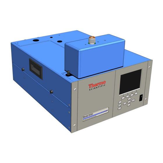
- Page 38 Physical Dimensions W: 16.75” (42.5 cm) x D: 23” (58.4 cm) x H: 8.62” (21.9 cm) Weight: 40 lbs. (19 kg) Optional/Accessories 6-foot extension tubes Tripod Outdoor Ambient Shelter with HVAC 1-10 Model 5030i SHARP Instruction Manual Thermo Fisher Scientific...
-
Page 39: Installation
In this configuration, the packaging is ready for shipping by carrier domestically and internationally. Thermo Fisher Scientific Model 5030i SHARP Instruction Manual... -
Page 40: Lifting
2. Remove the cover to expose the internal components. 3. Remove the packing material in the analyzer (Figure 2–1). Model 5030i SHARP Instruction Manual Thermo Fisher Scientific... -
Page 41: Acceptance Testing And Startup Procedures
This is an excellent opportunity to compare the monitor to the primary and transfer standards utilized by the end-user within their specific monitoring Thermo Fisher Scientific Model 5030i SHARP Instruction Manual... -
Page 42: Acceptance Test
▲ 2. Following a sufficient equilibration period, connect the power cord to the rear of the instrument and to a properly grounded power supply. Model 5030i SHARP Instruction Manual Thermo Fisher Scientific... - Page 43 The RH/Temperatures screen (read only) displays the current relative humidity in percent and the temperature readings in °C. The board temperature is the air temperature measured by a sensor located on the measurement interface board. Thermo Fisher Scientific Model 5030i SHARP Instruction Manual...
-
Page 44: Table 2-1. Pressure Units Conversion
Note Please be sure that the pump exhaust or any other heat source is not influencing the sensor reading of the temperature/RH cable assembly. Please be sure the side panel has been removed for at least 60 minutes. ▲ Model 5030i SHARP Instruction Manual Thermo Fisher Scientific... -
Page 45: One-Point Temperature Verification
Note The ambient temperature verification should be completed prior to performing the RH-sensor verification due to a thermal compensation applied to the RH-sensor. Furthermore, try to avoid RH comparisons <30% RH and >80% RH. ▲ Thermo Fisher Scientific Model 5030i SHARP Instruction Manual... -
Page 46: One-Point Barometric Pressure Verification
Diagnostics menu, and choose Flows. ● FLOW: 16.67 LPM RANGE DIAGS ALARM The Flow screen (read only) displays the volumetric flow rate in liters per minute. The flow is measured by the internal pressure board sensors. Model 5030i SHARP Instruction Manual Thermo Fisher Scientific... -
Page 47: Leak Check Procedure
For more information about the volumetric flow rate calibration, see the “Calibration” chapter. Leak Check The leak check of the 5030i SHARP is conducted by first measuring the volumetric flow rate at the inlet adapter. Next, place the factory-supplied Procedure leak check adapter on top of the inlet adapter and then install the flow- meter on top of the leak check adapter. -
Page 48: Setup
By reviewing the top view drawing of the instrument (Figure 2–3), the roof flange must be centered in direct alignment with the 5/8-inch OD tube entering the 5030i instrument. 2-10 Model 5030i SHARP Instruction Manual Thermo Fisher Scientific... -
Page 49: Heater
Based on the vertical height requirements, use additional 5/8-inch OD stainless tubing and connectors to make up the difference between the desired inlet height and the top of the heater. Additional routing is necessary for the ambient T/RH sensor assembly. Thermo Fisher Scientific Model 5030i SHARP Instruction Manual 2-11... -
Page 50: Figure 2-5. Model 5030I Vertical View
Sensor Assembly Tripod Adapter T/RH Sensor Cable Tripod 5/8 S.S. Tubing 5/8 Union w/Teflon Ferrule 3 Ft Universal Heater HEPA Filter 3-Way Valve Exhaust Intake Exhaust Figure 2–5. Model 5030i Vertical View 2-12 Model 5030i SHARP Instruction Manual Thermo Fisher Scientific... -
Page 51: Sample Tube Extension Lengths
2. Place 5030i unit in place of intended operation. 3. Attach the insulated heater tube assembly to the 5/8-inch OD tube on top of the 5030i (Figure 2–6). Thermo Fisher Scientific Model 5030i SHARP Instruction Manual 2-13... -
Page 52: Figure 2-6. Heater Assembly
7. Sleeve any additional water tight capping over the tubing that now extends above the roof line. 8. Sleeve the white Delrin plastic tripod adapter over the 5/8-inch OD tubing to an appropriate height to accommodate the tripod and 2-14 Model 5030i SHARP Instruction Manual Thermo Fisher Scientific... - Page 53 5030i. 17. Plug the pump power chord into the AC PUMP receptacle at the rear of the 5030i instrument. Thermo Fisher Scientific Model 5030i SHARP Instruction Manual 2-15...
-
Page 54: Figure 2-7. Rear Panel Plumbing Schematic
Installation Setup Heater Assembly 3-Ft. HEPA Filter RH Temperature Final Assembly SHARP Electric Connection Zero In Exhaust Pump Power Local PC Pump Zero Air Make-up Figure 2–7. Rear Panel Plumbing Schematic 2-16 Model 5030i SHARP Instruction Manual Thermo Fisher Scientific... -
Page 55: Connecting External Devices
Note Not all of the I/O available in the instrument is brought out on the supplied terminal board. If more I/O is desired, an alternative means of connection is required. See optional “Terminal Block and Cable Kits”. ▲ Thermo Fisher Scientific Model 5030i SHARP Instruction Manual 2-17... -
Page 56: Figure 2-8. I/O Terminal Board Views
Power_Fail_NC Analog ground Power_Fail_COM Analog2 Power_Fail_NO Analog ground TTL_Input1 Analog3 TTL_Input2 Analog ground TTL_Input3 Analog4 TTL_Input4 Analog ground Digital ground Analog5 TTL_Input5 Analog ground TTL_Input6 Analog6 TTL_Input7 Analog ground Digital ground 2-18 Model 5030i SHARP Instruction Manual Thermo Fisher Scientific... -
Page 57: D/O Terminal Board
D/O Terminal Board (customer supplied) to the terminal board using the included tie-down and spacer. Table 2–4 identifies the connector pins and associated signals. Thermo Fisher Scientific Model 5030i SHARP Instruction Manual 2-19... -
Page 58: Figure 2-10. D/O Terminal Board Views
The 25-pin terminal board is included with the optional I/O Expansion 25-Pin Terminal Board Board. Figure 2–11 shows the recommended method for attaching the cable (customer supplied) to the terminal board using the included tie- 2-20 Model 5030i SHARP Instruction Manual Thermo Fisher Scientific... -
Page 59: Figure 2-11. 25-Pin Terminal Board Views
Signal Description IOut1 Analog_In1 Isolated ground Analog_In2 IOut2 Analog_In3 Isolated ground Ground IOut3 Analog_In4 Isolated ground Analog_In5 IOut4 Analog_In6 Isolated ground Ground IOut5 Analog_In7 Isolated ground Analog_In8 IOut6 Ground Isolated ground Ground Thermo Fisher Scientific Model 5030i SHARP Instruction Manual 2-21... -
Page 60: Power Connections
Volumetric Conditions should be set to ACT for both Temp and Press vii. Lrecs and Srecs should be chosen for datalogging and all parameters should be selected in the order they appear from “Concentrations” to “Other Measurements”. Default Lrecs are 2-22 Model 5030i SHARP Instruction Manual Thermo Fisher Scientific... -
Page 61: Data Content
Do not expose the instrument to excessive vibration or magnetic ● interference. Do not remove/adjust the beta attenuation bench of the 5030i. ● Do not remove the C-14 radioactive source at any time. ● Thermo Fisher Scientific Model 5030i SHARP Instruction Manual 2-23... - Page 62 Installation Important Tips Operate the instrument in a climate-controlled environment ● (4–50 C). Set DHCP to ON when changing the IP address. ● 2-24 Model 5030i SHARP Instruction Manual Thermo Fisher Scientific...
-
Page 63: Operation
Some menus contain more items than can be displayed at one time. For these menus, use to move the cursor up and down to each item. Thermo Fisher Scientific Model 5030i SHARP Instruction Manual... -
Page 64: Pushbuttons
If the liquid crystal contacts your skin or clothes, wash it off immediately using soap and water. ▲ Pushbuttons The Pushbuttons allow the user to traverse the various screens/menus. Figure 3–2. Front Panel Pushbuttons Model 5030i SHARP Instruction Manual Thermo Fisher Scientific... -
Page 65: Soft Keys
All items under the Service menu (including the menu itself) cannot be assigned soft keys. ▲ Thermo Fisher Scientific Model 5030i SHARP Instruction Manual... -
Page 66: Alphanumeric Entry Screen
Run screens for ambient conditions, sample conditions, and mass sensor data. From the Run screen, the Main Menu can be displayed by pressing . The Main Menu contains a list of submenus. Each Model 5030i SHARP Instruction Manual Thermo Fisher Scientific... -
Page 67: Figure 3-3. Flowchart Of Menu-Driven Firmware
Operation Firmware Overview submenu contains related instrument settings. This chapter describes each submenu and screen in detail. Refer to the appropriate sections for more information. Figure 3–3. Flowchart of Menu-Driven Firmware Thermo Fisher Scientific Model 5030i SHARP Instruction Manual... -
Page 68: Power-Up Screen
The alarm (bell) icon indicates no parameter changes can be made from that an alarm is active. the front panel. The service (wrench) icon indicates that the instrument is in the service mode. Model 5030i SHARP Instruction Manual Thermo Fisher Scientific... -
Page 69: Ambient Conditions Run Screen
Status Bar AMBIENT CONDITIONS 16.67 FLOW 25.0 T AMB 760.0 P BAR 40.0 RH AMB Status Bar Icons 12:34 Status Bar RANGE DIAGS ALARM Thermo Fisher Scientific Model 5030i SHARP Instruction Manual... -
Page 70: Mass Sensor Data Run Screen
The Mass Sensor Data Run screen displays the real-time beta counts during Screen attenuation and the initial beta counts from a fresh filter spot. Title Bar MASS SENSOR DATA 9800.2 0000.9 ZERO Status Bar Icons 12:34 Status Bar RANGE DIAGS ALARM Model 5030i SHARP Instruction Manual Thermo Fisher Scientific... -
Page 71: Hybrid Data Run Screen
Mode” later in this chapter. to move the cursor up and down. ● Press to make a selection. ● Press to return to the Main Menu or to return to the ● Run screen. Thermo Fisher Scientific Model 5030i SHARP Instruction Manual... -
Page 72: Range Menu
Note If the units change, the instrument should be re-calibrated. A display warning will appear. ▲ In the Main Menu, choose Range > Conc Units. ● 3-10 Model 5030i SHARP Instruction Manual Thermo Fisher Scientific... -
Page 73: Table 3-2. Standard Ranges
DIAGS ALARM Table 3–2. Standard Ranges mg/m μg/m 1000 2000 3000 5000 10.00 10000 C1, C2, and C3 are custom ranges. For more information about custom ranges, see “Set Custom Ranges” below. Thermo Fisher Scientific Model 5030i SHARP Instruction Manual 3-11... -
Page 74: Set Custom Ranges
0.1 mg/m and 10.00 mg/m can be specified as a range. In the μg/m mode, any value between 100 μg/m and 10000 μg/m can be specified as a range. 3-12 Model 5030i SHARP Instruction Manual Thermo Fisher Scientific... -
Page 75: Custom Ranges
In the Main Menu, choose Integration Time. ● INTEGRATION TIME: CURRENTLY: 15 MIN SET TO: 20 MIN? CHANGE VALUE SAVE VALUE RANGE DIAGS ALARM Thermo Fisher Scientific Model 5030i SHARP Instruction Manual 3-13... -
Page 76: 24-Hour Average
(slope) are set to 0.0 and 1.0 by default. Should regional settings require an adjustment to these values that DO NOT compromise regulatory approvals for this instrument, those values can be adjusted at this point. In the Main Menu, choose Calibration Factors. ● 3-14 Model 5030i SHARP Instruction Manual Thermo Fisher Scientific... -
Page 77: Pm Background
NOT affected by the SET COEF until the value is saved. In the Main Menu, choose Calibration Factors > PM Coef. ● PM COEFFICIENT: CURRENTLY: 1.000 SET TO: 1.02 MOVE CURSOR CHANGE VALUE SAVE RANGE DIAGS ALARM Thermo Fisher Scientific Model 5030i SHARP Instruction Manual 3-15... -
Page 78: Sharp Background
The instrument can also be calibrated manually using this menu. For more information about calibration, see Chapter 4, “Calibration”. In the Main Menu, choose Calibration Factors > Neph Bkg Values. ● 3-16 Model 5030i SHARP Instruction Manual Thermo Fisher Scientific... -
Page 79: Nephelometer Mode
The Restore Previous Values screen is used to restore the prior background values should a poor zero occur. In the Main Menu, choose Calibration Factors > Neph Bkg > ● Restore Prev Values. Thermo Fisher Scientific Model 5030i SHARP Instruction Manual 3-17... -
Page 80: Nephelometer Coefficient
The Instrument Controls menu contains a number of items that may be selected to control various instrument operational parameters. The Menu firmware controls listed in this menu enable control of the listed instrument functions. In the Main Menu, choose Instrument Controls. ● 3-18 Model 5030i SHARP Instruction Manual Thermo Fisher Scientific... -
Page 81: Set Flow/Pump
DIAGS ALARM Pump The Pump screen allows the user to toggle the pump to either ON or OFF. In the Main Menu, choose Instrument Controls > Set Flow/Pump > ● Pump. Thermo Fisher Scientific Model 5030i SHARP Instruction Manual 3-19... -
Page 82: Set Heater
The RH Threshold screen is used to change the RH threshold value in percent. The RH threshold is typically compatible with the gravimetric method being used for comparison. In the Main Menu, choose Instrument Controls > Set Heater > RH ● Threshold. 3-20 Model 5030i SHARP Instruction Manual Thermo Fisher Scientific... -
Page 83: Temperature Threshold
The Manual screen allows the user to move or stop the filter tape and open or close the measurement bench. In the Main Menu, choose Instrument Controls > Filter Tape ● Control > Manual. Thermo Fisher Scientific Model 5030i SHARP Instruction Manual 3-21... -
Page 84: Mass Limit
The official tape change for TUV and U.S. EPA for PM and PM is set for 8 hours. 3-22 Model 5030i SHARP Instruction Manual Thermo Fisher Scientific... -
Page 85: Counter
In the Main Menu, choose Instrument Controls > Filter Tape ● Control > Tape/Zero Ratio. TAPE/NEPH ZERO RATIO: CURRENTLY: SET TO: 2:1 ? CHANGE VALUE SAVE VALUE RANGE DIAGS ALARM Thermo Fisher Scientific Model 5030i SHARP Instruction Manual 3-23... -
Page 86: Volumetric Conditions
The Standard Temperature screen is used to set the standard temperature. In the Main Menu, choose Instrument Controls > Volumetric ● Conditions > Temperature > Standard. STANDARD TEMPERATURE: CURRENTLY: SET TO: INC/DEC SAVE VALUE RANGE DIAGS ALARM 3-24 Model 5030i SHARP Instruction Manual Thermo Fisher Scientific... -
Page 87: Pressure Compensation
The analyzer's computer system includes three megabytes of flash memory which is enough to store a full lrec containing 32 data items and a full srec Thermo Fisher Scientific Model 5030i SHARP Instruction Manual 3-25... -
Page 88: Select Srec/Lrec
In the Main Menu, choose Instrument Controls > Datalogging ● Settings > View Logged Data. 3-26 Model 5030i SHARP Instruction Manual Thermo Fisher Scientific... -
Page 89: Number Of Records
“20 Jan 2009 10:01”. DATE AND TIME: 20 JAN 2009 10:00 DAYS SET CURSOR TO MONTHS ACCEPT AS SHOWN RANGE DIAGS ALARM Thermo Fisher Scientific Model 5030i SHARP Instruction Manual 3-27... -
Page 90: Erase Log
In the Main Menu, choose Instrument Controls > Datalogging ● Settings > Select Content. 3-28 Model 5030i SHARP Instruction Manual Thermo Fisher Scientific... -
Page 91: Choose Field Data
In the Main Menu, choose Instrument Controls > Datalogging ● Settings > Select Content > select Field > Concentrations. CONCENTRATIONS: >NONE <-- AVG PM NEPH SHARP RANGE DIAGS ALARM AVG SHARP AVG NEPH Thermo Fisher Scientific Model 5030i SHARP Instruction Manual 3-29... -
Page 92: Other Measurements
BRD TEMP FLOW TEMP FLOW VOL BETA BETA ALPHA RAW MASS BETA ZERO EXT ALARMS NEPH TEMP NEPH RH NEPH IRED NEPH REF BETA REF COMMON FLAGS DET FLAGS MASS COMP 3-30 Model 5030i SHARP Instruction Manual Thermo Fisher Scientific... -
Page 93: Analog Inputs
Figure 3–6. Detector A Flags Analog Inputs The Analog Inputs screen allows the user to select the parameter (none or analog inputs 1–8) to the selected record field. The selected item is shown Thermo Fisher Scientific Model 5030i SHARP Instruction Manual 3-31... -
Page 94: Commit Content
For more information about selecting the content of logged data fields, see “Select Content” above. In the Main Menu, choose Instrument Controls > Datalogging ● Settings > Reset to Default Content. 3-32 Model 5030i SHARP Instruction Manual Thermo Fisher Scientific... -
Page 95: Configure Datalogging
Percentages between 0 and 100% are available in increments of 10. Changing this value results in log erasure for both types of records, and changing the percent allocated to one record type will automatically change the other. Thermo Fisher Scientific Model 5030i SHARP Instruction Manual 3-33... -
Page 96: Data Treatment
The Flag Status Data screen is used to set the flag status data to either ON or OFF for the selected record type. In the Main Menu, choose Instrument Controls > Datalogging ● Settings > Configure Datalogging > Flag Status Data. 3-34 Model 5030i SHARP Instruction Manual Thermo Fisher Scientific... -
Page 97: Communication Settings
The analyzer’s default baud rate is set to 9600 to provide backwards compatibility with the older C-series analyzers. In the Main Menu, choose Instrument Controls > Communication ● Settings > Serial Settings > Baud Rate. Thermo Fisher Scientific Model 5030i SHARP Instruction Manual 3-35... -
Page 98: Baud Rate
The Stop Bits screen is used to set the number of stop bits for the serial port to 1 (default) or 2. In the Main Menu, choose Instrument Controls > Communication ● Settings > Serial Settings > Stop Bits. 3-36 Model 5030i SHARP Instruction Manual Thermo Fisher Scientific... -
Page 99: Rs-232/Rs-485 Selection
0 to 127. The Model 5030i has a default instrument ID of 14. For more information about the instrument ID, see Appendix B “C-Link Protocol” or Appendix C “MODBUS Protocol”. In the Main Menu, choose Instrument Controls > Communication ● Settings > Instrument ID. Thermo Fisher Scientific Model 5030i SHARP Instruction Manual 3-37... -
Page 100: Gesytec Serial Nunber
8 streaming data output items, streaming interval, current data format, and current timestamp setting. The Choose Stream Data submenu displays a list of the analog output signal group choices to choose from. 3-38 Model 5030i SHARP Instruction Manual Thermo Fisher Scientific... -
Page 101: Streaming Data Interval
Choices are Concentrations, Other Measurements, and Analog Inputs (if the I/O expansion board is installed). In the Main Menu, choose Instrument Controls > Communication ● Settings > Streaming Data Config > Item 1–8. Thermo Fisher Scientific Model 5030i SHARP Instruction Manual 3-39... -
Page 102: Choose Stream Data
Flags and Detector A Flags, see Figure 3–5 Figure 3–6 for data descriptions. In the Main Menu, choose Instrument Controls > Communication ● Settings > Streaming Data Config > select Item > Other Measurements. 3-40 Model 5030i SHARP Instruction Manual Thermo Fisher Scientific... - Page 103 The TCP/IP Settings menu is used for defining parameters that are required for Ethernet communications. Note The instrument power must be cycled after any of these parameters have been changed for the change to take effect. ▲ Thermo Fisher Scientific Model 5030i SHARP Instruction Manual 3-41...
-
Page 104: Tcp/Ip Settings
In the Main Menu, choose Instrument Controls > Communication ● Settings > TCP/IP Settings > IP Addr. IP ADDRESS: CURRENT: 10.209.40.149 SET TO: 10.209.40.149 1 MOVE CURSOR CHANGE VALUE SAVE VALUE RANGE DIAGS ALARM 3-42 Model 5030i SHARP Instruction Manual Thermo Fisher Scientific... -
Page 105: Use Dhcp
The Host Name screen is used to edit the host name. When DHCP is enabled, this name is reported to the DHCP server. In the Main Menu, choose Instrument Controls > Communication ● Settings > TCP/IP Settings > Host Name. Thermo Fisher Scientific Model 5030i SHARP Instruction Manual 3-43... -
Page 106: Host Name
The Output Relay Settings menu displays a list of the 10 digital output relays available, and allows the user to select the logic state and instrument parameter for the relay selected. 3-44 Model 5030i SHARP Instruction Manual Thermo Fisher Scientific... -
Page 107: Logic State
In the Main Menu, choose Instrument Controls > I/O Configuration ● > Output Relay Settings > select Relay > Instrument State. CHOOSE SIGNAL TYPE: >ALARMS NON-ALARM RANGE DIAGS ALARM Thermo Fisher Scientific Model 5030i SHARP Instruction Manual 3-45... -
Page 108: Alarms
Note The digital inputs must be asserted for at least one second for the action to be activated. ▲ 3-46 Model 5030i SHARP Instruction Manual Thermo Fisher Scientific... -
Page 109: Digital Input Settings
The Instrument Action submenu allows the user to choose the instrument action that is assigned to the selected digital input. In the Main Menu, choose Instrument Controls > I/O Configuration ● > Digital Input Settings > select Relay > Instrument Action. Thermo Fisher Scientific Model 5030i SHARP Instruction Manual 3-47... -
Page 110: Analog Output Configuration (Select Channel)
4 mA. By default, this parameter is set to on and 5% over and under range is allowed for all analog output channels. In the Main Menu, choose Instrument Controls > I/O Configuration ● > Analog Output Config > Allow Over/Under Range. 3-48 Model 5030i SHARP Instruction Manual Thermo Fisher Scientific... -
Page 111: Analog Output Configuration (Select Action)
SAVE RANGE DIAGS ALARM Minimum and Maximum The Minimum and Maximum Value screens are used to edit the zero (0) Value and full-scale (100) values, respectively, in percentages for the selected Thermo Fisher Scientific Model 5030i SHARP Instruction Manual 3-49... -
Page 112: Table 3-4. Analog Output Zero To Full-Scale
User-set alarm min value User-set alarm max value Beta Raw User-set alarm min value User-set alarm max value Alpha Raw User-set alarm min value User-set alarm max value Mass -200 5,000 Beta Zero 65,000 3-50 Model 5030i SHARP Instruction Manual Thermo Fisher Scientific... -
Page 113: Table 3-5. Signal Type Group Choices
CHANGE VALUE SAVE RANGE DIAGS ALARM Table 3–5. Signal Type Group Choices Concentrations Other Measurements Analog Inputs None None None Barometer Pressure Analog Input 1 (if the I/O expansion Thermo Fisher Scientific Model 5030i SHARP Instruction Manual 3-51... -
Page 114: Analog Input Configuration
This screen is only displayed if the I/O expansion board option is installed. Configuration includes entering the Descriptor, Units, Decimal Places, choice of 1–10 points in the table, and corresponding number of points selected. 3-52 Model 5030i SHARP Instruction Manual Thermo Fisher Scientific... -
Page 115: Descriptor
The units may be from 1 to 3 characters in length, and defaults to V (volts). In the Main Menu, choose Instrument Controls > I/O Configuration ● > Analog Input Config > select Channel > Units. Thermo Fisher Scientific Model 5030i SHARP Instruction Manual 3-53... -
Page 116: Number Of Table Points
In the Main Menu, choose Instrument Controls > I/O Configuration ● > Analog Input Config > select Channel > Table Points. NUMBER OF TABLE POINTS: CURRENTLY: SET TO: 10 ? INC/DEC SAVE VALUE RANGE DIAGS ALARM 3-54 Model 5030i SHARP Instruction Manual Thermo Fisher Scientific... -
Page 117: Volts
1: 0.00 V = 000.0 U and point 2: 10.00 V = 10.0 U, where U is the previously entered unit of measure. In the Main Menu, choose Instrument Controls > I/O Configuration ● > Analog Input Config > select Channel > select Point > User Value. Thermo Fisher Scientific Model 5030i SHARP Instruction Manual 3-55... -
Page 118: Screen Contrast
Model 5030i. The service (wrench) icon on the status bar is shown when service mode is on. For more information about the service mode, see “Service Menu” later in this chapter. 3-56 Model 5030i SHARP Instruction Manual Thermo Fisher Scientific... -
Page 119: Date/Time
(GMT+7/6), and PDT (GMT+8/7). Note The current timezone may say NULL before the timezone is set for the first time, or if the timezone was cleared with a C-Link command. ▲ Thermo Fisher Scientific Model 5030i SHARP Instruction Manual 3-57... -
Page 120: Diagnostics Menu
Prior to contacting the factory with any questions regarding the instrument, please note the product model name and the program version numbers. In the Main Menu, choose Diagnostics > Program Versions. ● 3-58 Model 5030i SHARP Instruction Manual Thermo Fisher Scientific... -
Page 121: Voltages
Interface Board Voltages The Interface Board screen (read only) is used to display the voltage readings on the measurement interface board. In the Main Menu, choose Diagnostics > Voltages > Interface ● Board. Thermo Fisher Scientific Model 5030i SHARP Instruction Manual 3-59... -
Page 122: Interface Board Voltages
Nephelometer Board The Nehpelometer Board screen (read only) is used to display the voltage Voltages readings on the nephelometer board. In the Main Menu, choose Diagnostics > Voltages > Nephelometer ● Board. 3-60 Model 5030i SHARP Instruction Manual Thermo Fisher Scientific... -
Page 123: Rh/Temperature
Flow The Flow screen (read only) displays the current sample flow reading. The flow is measured by the internal pressure board sensors. In the Main Menu, choose Diagnostics > Flow. ● Thermo Fisher Scientific Model 5030i SHARP Instruction Manual 3-61... -
Page 124: Detector Status
36.6 LED CURRENT 69.8 mA REF DETECTOR 867 mV RANGE DIAGS ALARM The CRn screen (read only) displays the current CRn reading. In the Main Menu, choose Diagnostics > CRn. ● 3-62 Model 5030i SHARP Instruction Manual Thermo Fisher Scientific... -
Page 125: Analog Input Readings
Pull-ups are provided on all of the inputs, so if nothing they will read (1), if an input is brought to ground, it will read (0). In the Main Menu, choose Diagnostics > Digital Inputs. ● Thermo Fisher Scientific Model 5030i SHARP Instruction Manual 3-63... -
Page 126: Relay States
Full-scale sets the analog outputs to the full- scale voltage, zero sets the analog outputs to 0 volts, and reset returns the output to normal operation. The analog outputs are returned to normal 3-64 Model 5030i SHARP Instruction Manual Thermo Fisher Scientific... -
Page 127: Set Analog Outputs
DIAGS ALARM Contact Information The Contact Information screen displays the customer service information. In the Main Menu, choose Diagnostics > Contact Information. ● CONTACT INFORMATION: CALL CENTER: 508-520-0430 http://WWW.THERMO.COM/AQI RANGE DIAGS ALARM Thermo Fisher Scientific Model 5030i SHARP Instruction Manual 3-65... -
Page 128: Alarms Menu
(if installed) indicate that the power supplies are working and connections are successful. There are no setting screens for these alarms. In the Main Menu, choose Alarms > Instrument Alarms. ● 3-66 Model 5030i SHARP Instruction Manual Thermo Fisher Scientific... -
Page 129: Filter Tape Counter
Board status indicates that the power supplies are working and connections are successful. There are no setting screens for this alarm. In the Main Menu, choose Alarms > Detector Alarms. ● Thermo Fisher Scientific Model 5030i SHARP Instruction Manual 3-67... -
Page 130: Min And Max Alpha Alarms
The Nephelometer Alarms submenu allows the user to view and set the nephelometer alarm parameters. Board status indicates that the power Alarms supplies are working and connections are successful. The nephelometer 3-68 Model 5030i SHARP Instruction Manual Thermo Fisher Scientific... -
Page 131: Nephelometer Temperature
The Nephelometer minimum and maximum nephelometer temperature screens function the Temperature Limits same way. In the Main Menu, choose Alarms > Neph Alarms > Neph Temp > ● Min or Max. Thermo Fisher Scientific Model 5030i SHARP Instruction Manual 3-69... -
Page 132: Nephelometer Rh
The LED Current screen displays the current nephelometer source current value and sets the minimum and maximum alarm limits. Acceptable alarm limits range from 50 to 70 mA. If the LED current reading goes beyond 3-70 Model 5030i SHARP Instruction Manual Thermo Fisher Scientific... -
Page 133: Led Current
Run screen and in the Main Menu. There is no “set” mode for this value. In the Main Menu, choose Alarms > Neph Alarms > Ref Det Volt. ● REF DETECTOR VOLTAGE: ACTUAL 780 mV 350 mV 2000 mV RANGE DIAGS ALARM Thermo Fisher Scientific Model 5030i SHARP Instruction Manual 3-71... -
Page 134: Rh/Temperature Alarms
RH alarm limit. The minimum and maximum ambient Limits RH screens function the same way. In the Main Menu, choose Alarms > RH/Temperature Alarms > ● Ambient RH > Min or Max. 3-72 Model 5030i SHARP Instruction Manual Thermo Fisher Scientific... -
Page 135: Sample Rh
Acceptable alarm limits range from -30 °C to 60 °C. If the ambient temperature reading goes beyond the minimum or maximum limit, an alarm is activated and the Thermo Fisher Scientific Model 5030i SHARP Instruction Manual 3-73... -
Page 136: Ambient Temperature
Run screen and in the Main Menu. In the Main Menu, choose Alarms > RH/Termperature Alarms > ● Flow Temp. FLOW TEMP: ACTUAL 24.4 >MIN 60.0 RANGE DIAGS ALARM 3-74 Model 5030i SHARP Instruction Manual Thermo Fisher Scientific... -
Page 137: Flow Temperature
The minimum and maximum Temperature Limits board temperature screens function the same way. In the Main Menu, choose Alarms > RH/Temperature Alarms > ● Board Temp > Min or Max. Thermo Fisher Scientific Model 5030i SHARP Instruction Manual 3-75... -
Page 138: Pressure/Vacuum Alarms
The minimum and maximum Pressure Limits barometric pressure screens function the same way. In the Main Menu, choose Alarms > Pressure/Vacuum Alarms > Baro ● Pres > Min or Max. 3-76 Model 5030i SHARP Instruction Manual Thermo Fisher Scientific... -
Page 139: Vacuum
In the Main Menu, choose Alarms > Pressure/Vacuum Alarms > ● Vacuum > Min or Max. VACUUM: ACTUAL MIN: -5.0 mmHg SET MIN TO: -4.9 mmHg? INC/DEC SAVE VALUE RANGE DIAGS ALARM Thermo Fisher Scientific Model 5030i SHARP Instruction Manual 3-77... -
Page 140: Flow
SAVE VALUE RANGE DIAGS ALARM Flow Alarms The Flow Alarms submenu allows the user to view and set the flow alarm parameters. In the Main Menu, choose Alarms > Flow Alarms. ● 3-78 Model 5030i SHARP Instruction Manual Thermo Fisher Scientific... -
Page 141: Flow
The Concentration Alarms submenu allows the user to view and set the 24- hour average concentration and the instant concentration for PM, SHARP, and nephelometer alarm parameters. In the Main Menu, choose Alarms > Conc Alarms. ● Thermo Fisher Scientific Model 5030i SHARP Instruction Manual 3-79... -
Page 142: Average Pm
In the Main Menu, choose Alarms > Conc Alarms > Avg PM > Min ● or Max. AVERAGE PM CONC: ACT MIN: SET MIN: xxxxx100 MOVE CURSOR CHANGE VALUE SAVE RANGE DIAGS ALARM 3-80 Model 5030i SHARP Instruction Manual Thermo Fisher Scientific... -
Page 143: Average Sharp
(bell) icon appears in the status bar on the Run screen and in the Main Menu. In the Main Menu, choose Alarms > Conc Alarms > Avg Neph. ● Thermo Fisher Scientific Model 5030i SHARP Instruction Manual 3-81... -
Page 144: Instant Pm
10000 RANGE DIAGS ALARM Min and Max Instant PM The Minimum Instant PM Concentration alarm limit screen is used to change the minimum instant PM concentration alarm limit. The Concentration Limits 3-82 Model 5030i SHARP Instruction Manual Thermo Fisher Scientific... -
Page 145: Instant Sharp
SHARP concentration alarm limit. The minimum and maximum instant SHARP concentration screens function Limits the same way. In the Main Menu, choose Alarms > Conc Alarms > Inst SHARP > ● Min or Max. Thermo Fisher Scientific Model 5030i SHARP Instruction Manual 3-83... -
Page 146: Instant Nephelometer
In the Main Menu, choose Alarms > Conc Alarms > Inst Neph > ● Min or Max. INSTANT NEPH CONC: ACT MIN: SET MIN: xxxxx-10 MOVE CURSOR CHANGE VALUE SAVE RANGE DIAGS ALARM 3-84 Model 5030i SHARP Instruction Manual Thermo Fisher Scientific... -
Page 147: Service Menu
For more information on the service mode, see “Service Mode” earlier in this chapter. Note This adjustment should only be performed by an instrument service technician. ▲ In the Main Menu, choose Service > RH/Temp Calibration. ● Thermo Fisher Scientific Model 5030i SHARP Instruction Manual 3-85... -
Page 148: Ambient Temperature
The Ambient Relative Humidity screen allows the user to view and calibrate relative humidity. Adjust the zero offset until the RH agrees with Humidity your treaceable standard. In the Main Menu, choose Service > RH/Temp Calibration > ● Ambient RH. 3-86 Model 5030i SHARP Instruction Manual Thermo Fisher Scientific... -
Page 149: Pressure/Vacuum Calibration
Calibration In the Main Menu, choose Service > Pres/Vacuum Calibration > ● Baro Pres. BARO PRES CALIBRATION: >OFFSET SPAN 1.0000 SET DEFAULTS RANGE DIAGS ALARM Thermo Fisher Scientific Model 5030i SHARP Instruction Manual 3-87... -
Page 150: Calibrate Barometer Pressure Offset
The Restore Default Calibration screen allows the user to reset the default values. Calibration In the Main Menu, choose Service > Pres/Vacuum Calibration > ● Baro Pres Calibration > Set Defaults. 3-88 Model 5030i SHARP Instruction Manual Thermo Fisher Scientific... -
Page 151: Vacuum/Flow Calibration
The Calibrate Vacuum Pressure Span screen allows the user to view and set Pressure Span the flow sensor calibration span point. Note The operator should use an independent manometer capable of measuring approximately 100 mmHg of vacuum. Measure the vacuum Thermo Fisher Scientific Model 5030i SHARP Instruction Manual 3-89... -
Page 152: Calibrate Flow Pressure Span
The Restore Default Calibration screen allows the user to reset the default values. Calibration Note Be sure to close the toggle switch after calibration is complete. ▲ In the Main Menu, choose Service > Pres/Vacuum Calibration > ● Vac/Flow > Set Defaults. 3-90 Model 5030i SHARP Instruction Manual Thermo Fisher Scientific... -
Page 153: Flow Calibration
In the Main Menu, choose Service > Flow Calibration > Auto. ● FLOW AUTO CALIBRATION: FLOW: 16.67 LPM SET TO: 17.25 LPM? MOVE CURSOR CHANGE VALUE SAVE RANGE DIAGS ALARM Thermo Fisher Scientific Model 5030i SHARP Instruction Manual 3-91... -
Page 154: Manual Flow Calibration
The Thermal Mass Coefficient screen allows the user to view and set the thermal coefficient using manual calibration mode. (Factory set.) In the Main Menu, choose Service > Mass Calibration > Thermal ● Coefficient. 3-92 Model 5030i SHARP Instruction Manual Thermo Fisher Scientific... -
Page 155: Thermal Mass Coefficient
The Mass Coefficient submenu allows the user to view and set the mass coefficient using manual or auto mode. (Factory set.) In the Main Menu, choose Service > Mass Calibration > Mass ● Coefficient. Thermo Fisher Scientific Model 5030i SHARP Instruction Manual 3-93... -
Page 156: Auto Mass Coefficient
6992 MOVE CURSOR CHANGE VALUE SAVE RANGE DIAGS ALARM Alpha Efficiency The Alpha Efficiency Coefficient screen allows the user to view and set the Coefficient alpha efficiency value. 3-94 Model 5030i SHARP Instruction Manual Thermo Fisher Scientific... -
Page 157: Detector Calibration
This process takes approximately 30 minutes and will set a high voltage and thresholds for alpha and beta reference counts. In the Main Menu, choose Service > Detector Calibration > Auto. ● Thermo Fisher Scientific Model 5030i SHARP Instruction Manual 3-95... -
Page 158: Manual Detector Calibration
High Voltage The High Voltage screen allows the user to view and set the high voltage value. In the Main Menu, choose Service > Detector Calibration > Manual ● > High Voltage. 3-96 Model 5030i SHARP Instruction Manual Thermo Fisher Scientific... -
Page 159: Alpha Threshold
For more information on the service mode, see “Service Mode” earlier in the chapter. Note This adjustment should only be performed by an instrument service technician. ▲ Thermo Fisher Scientific Model 5030i SHARP Instruction Manual 3-97... -
Page 160: Nephelometer Rh
Nephelometer Source The Nephelometer Source Level screen allows the user to view and calibrate the source level. Level In the Main Menu, choose Service > Neph Calibration > Neph Src ● Level. 3-98 Model 5030i SHARP Instruction Manual Thermo Fisher Scientific... -
Page 161: Analog Output Calibration
0 or 4 mA for a current channel (depending on the selected range). See the “set output to:” field on the display. In the Main Menu, choose Service > Analog Out Cal > select ● Channel > Calibrate Zero. Thermo Fisher Scientific Model 5030i SHARP Instruction Manual 3-99... -
Page 162: Analog Input Calibration
For more information on the service mode, “Service Mode” earlier in this chapter. Note This adjustment should only be performed by an instrument service technician. ▲ In the Main Menu, choose Service > Analog Input Calibration. ● 3-100 Model 5030i SHARP Instruction Manual Thermo Fisher Scientific... -
Page 163: Analog Input Calibrate Zero
Channel > Calibrate Full Scale. (Hook up a voltage source of 10 V to the analog input channel.) ANALOG INPUT CAL: SPAN PROVIDE VOLTAGE TO INPUT! SELECTED INPUT: INPUT 1 CURRENTLY: 9.84 V SET TO: 10.00 CALIBRATE TO VALUE RANGE DIAGS ALARM Thermo Fisher Scientific Model 5030i SHARP Instruction Manual 3-101... -
Page 164: Display Pixel Test
For more information on the service mode, see “Service Mode” earlier in this chapter. In the Main Menu, choose Service > Restore User Defaults. ● 3-102 Model 5030i SHARP Instruction Manual Thermo Fisher Scientific... - Page 165 In the Main Menu, choose Password > Set Password ● ENTER NEW PASSWORD: RANGXXXXXE ABCDEFGHIJKLMN BKSP OPQRSTUVWXYZ PAGE 0123456789 ./- SAVE RANGE DIAGS ALARM Thermo Fisher Scientific Model 5030i SHARP Instruction Manual 3-103...
- Page 166 The change password screen is shown if the instrument is unlocked. In the Main Menu, choose Password > Change Password ● ENTER NEW PASSWORD: RANGXXXXXE ABCDEFGHIJKLMN BKSP OPQRSTUVWXYZ PAGE 0123456789 ./- SAVE RANGE DIAGS ALARM 3-104 Model 5030i SHARP Instruction Manual Thermo Fisher Scientific...
- Page 167 The unlock instrument screen is shown if the instrument is locked. In the Main Menu, choose Password > Unlock Instrument ● ENTER THE PASSWORD: RANGXXXXXE ABCDEFGHIJKLMN BKSP OPQRSTUVWXYZ PAGE 0123456789 ./- SAVE RANGE DIAGS ALARM Thermo Fisher Scientific Model 5030i SHARP Instruction Manual 3-105...
- Page 169 The following equipment should be used: A thermistor or thermocouple thermometer capable of measuring ● ambient temperatures in a range of –20 to 50 °C, readable to the Thermo Fisher Scientific Model 5030i SHARP Instruction Manual...
- Page 170 The Calibration submenus allow the user to view and calibrate the instrument. All calibration submenus are visible only when the instrument is in service mode. For more information on the service mode, “Service Mode” earlier in Chapter 3. Model 5030i SHARP Instruction Manual Thermo Fisher Scientific...
- Page 171 DIAGS ALARM Be sure to save the entry and compare the values once more. If it appears that the temperature has shifted into the wrong direction, change the sign of your offset value. Thermo Fisher Scientific Model 5030i SHARP Instruction Manual...
- Page 172 Using a NIST-traceable barometer, measure the barometric pressure (and Calibration convert as necessary) in units of millimetres of mercury (mmHg). Use the SPAN feature from the barometric calibration submenu. BARO PRES CALIBRATION: >SPAN 1.0000 SET DEFAULTS RANGE DIAGS ALARM Model 5030i SHARP Instruction Manual Thermo Fisher Scientific...
- Page 173 100 mmHg) and attach to the +PA port on the rear panel. Then push the toggle switch on the right inward to open (see Figure 4–1). The manometer reading can now be used to calibrate the vacuum sensor. Thermo Fisher Scientific Model 5030i SHARP Instruction Manual...
-
Page 174: Figure 4-1. Differential Pressure And Vacuum Calibration Ports
Open the ports by pressing the toggle switches inward. Calculate an average reading from the reference manometer in units of mmHg. Enter this span value into the screen below: Model 5030i SHARP Instruction Manual Thermo Fisher Scientific... -
Page 175: Flow Calibration
Mass Calibration The Model 5030i SHARP is calibrated for mass in the factory using a series of null and span foils. The mass transfer standard foil sets are available from Thermo Fisher Scientific, and should be used as part of a QA Program for performing a QC check on the mass measurements. - Page 176 Since the beta attenuation method is linear with mass increase, the Model 5030i need not be calibrated in the exact range of beta attenuation per filter spot. What is important, is calibrating the corresponding beta count reduction with an increase of calibrated mass. Model 5030i SHARP Instruction Manual Thermo Fisher Scientific...
- Page 177 The beta attenuation chamber should now open. MASS COEF: 7000.0 FOIL VALUE: 1328 μg TO SAVE FOIL VALUE AND OPEN BENCH RANGE DIAGS ALARM Thermo Fisher Scientific Model 5030i SHARP Instruction Manual...
- Page 178 TO CONTINUE RANGE DIAGS ALARM 5. Remove the zero/null foil and insert with the Span foil (e.g., 1328 ug) and press to begin the span calibration, or press to stop the foil. 4-10 Model 5030i SHARP Instruction Manual Thermo Fisher Scientific...
- Page 179 MASS COEF: 6878.7 FOIL VALUE: 1328 μg Beta Avg 9911 1/sec difference -1.7 % REMOVE HOLDE, INSERT TAPE, TO CLOSE BENCH RANGE DIAGS ALARM Thermo Fisher Scientific Model 5030i SHARP Instruction Manual 4-11...
-
Page 180: Detector Calibration
TO START AUTO CAL RANGE DIAGS ALARM This procedure will take approximately 30 minutes until completed. Thereafter, a high voltage (HV), beta reference threshold and alpha threshold will be assigned a new valve. 4-12 Model 5030i SHARP Instruction Manual Thermo Fisher Scientific... - Page 181 The Nephelometer Temperature screen allows the user to view and calibrate the nephelometer temperature sensor calibration. Temperature Note Calibration of the nephelometer temperature must be done with the heater in the “OFF” position. ▲ Thermo Fisher Scientific Model 5030i SHARP Instruction Manual 4-13...
- Page 182 In the Main Menu, choose Service > Neph Calibration > Neph Src ● Level. SOURCE LEVEL SET: IRED: 65 mA SRC LEVEL: 32 % INC/DEC SAVE VALUE RANGE DIAGS ALARM 4-14 Model 5030i SHARP Instruction Manual Thermo Fisher Scientific...
- Page 183 Equipment Damage Some internal components can be damaged by small amounts of static electricity. A properly grounded antistatic wrist strap must be worn while handling any internal component. For more information about appropriate safety precautions, see the “Servicing” chapter. ▲ Thermo Fisher Scientific Model 5030i SHARP Instruction Manual...
-
Page 184: Chapter 5 Preventive Maintenance
(Figure 5–1). Remove any accumulated water, clean the interior of the bottle, inspect the seals, and replace the bottle in the holder. Model 5030i SHARP Instruction Manual Thermo Fisher Scientific... -
Page 185: European Pm /Pm Inlet
Leckel), at approximately a 1-2 month interval. The components of the Inlet inlet should be inspected and cleaned as necessary. Figure 5–2 provided below provides an image and design drawing of the inlet, with references to parts. Thermo Fisher Scientific Model 5030i SHARP Instruction Manual... -
Page 186: Figure 5-2. European Pm
Once every three months, the entire SCC assembly should be inspected and cleaned, O-rings checked for distortion, cracks, fraying, or other problems. Replace O-rings as necessary. Model 5030i SHARP Instruction Manual Thermo Fisher Scientific... -
Page 187: Heater And Sample Tube
2. Flush the filter with warm water and let dry (a clean, oil-free purge will help the drying process) or blow the filter clean with compressed air. 3. Re-install the filter and fan guard. Thermo Fisher Scientific Model 5030i SHARP Instruction Manual... -
Page 188: Pump Rebuilding
Use the following procedure to verify no leaks. 1. Place a reference volumetric flow meter (e.g., BGI Delta Cal) onto the inlet adapter and calibrate the 5030i SHARP so that the reference flow meter and the 5030i SHARP Monitor read the same flow rate. -
Page 189: Filter Tape Replacement
9. Tighten right reel nut. From Filter Tape Control > Manual > choose Tape and press to MOVE tape. 10. From the main menu choose Alarms > Instrument Alarms to verify that there are no filter tape alarms. 11. Replace left side cover. Thermo Fisher Scientific Model 5030i SHARP Instruction Manual... -
Page 190: Greasing The Cam
Equipment Damage Some internal components can be damaged by small amounts of static electricity. A properly grounded antistatic wrist strap must be worn while handling any internal component. For more information about appropriate safety precautions, see the “Servicing” chapter. ▲ Model 5030i SHARP Instruction Manual Thermo Fisher Scientific... -
Page 191: Figure 5-6. Replacing The External Pump Exhaust Filter
4. Remove sealing gasket (note: may be stuck to bottomside of top-end plate). 5. Carefully vacuum out optic chamber. 6. Re-assemble in reverse order—note careful placement of the sealing gasket. HEPA Filter Figure 5–6. Replacing the External Pump Exhaust Filter Thermo Fisher Scientific Model 5030i SHARP Instruction Manual... -
Page 192: Cleaning The Sharp Optics Assembly
6. Carefully vacuum out the optics chamber using caution not to scrap the interior of the optics chamber. 7. Re-assemble following the previous steps. Take extra caution in re- aligning the sealing gasket to avoid air leaks. 5-10 Model 5030i SHARP Instruction Manual Thermo Fisher Scientific... - Page 193 Table 6–2 lists all the alarm messages you may see on the graphics display and provides recommendations about how to resolve the alarm condition. Thermo Fisher Scientific Model 5030i SHARP Instruction Manual...
-
Page 194: Chapter 6 Troubleshooting
Replace one board at a time with a spare board to isolate the defective board. Verify P valves on rear panel are Flow in the closed position. Re-calibrate. Display is off Wrong contrast setting Adjust contrast setting. Model 5030i SHARP Instruction Manual Thermo Fisher Scientific... - Page 195 Check P calibration valve are Close valves. in closed position Neph Board Failures External cable not connected Check cable connection. Internal cable not connected. Check cable connection. Low Source Current Disconnected Source/Ref Check cable connection. cable Thermo Fisher Scientific Model 5030i SHARP Instruction Manual...
- Page 196 Bad Zero Re-zero Neph Temp High/Low Check min and max values/ Re-calibrate Neph RH Low/High Check min and max values/ Re-calibrate Led Current High/Low Check min and max values/Verify 65mA ± 5mA Model 5030i SHARP Instruction Manual Thermo Fisher Scientific...
-
Page 197: Table 6-2. Troubleshooting - Alarm Messages
Disconnected cable Verify cable harness is connected to Board Status the base. WARNING If disconnected, turn off AC power to the base before re- connecting. Nephelometer Alarms – Bad zero Re-zero. Neph Sample Thermo Fisher Scientific Model 5030i SHARP Instruction Manual... - Page 198 RH/Temperature Alarms – Disconnected cable Verify connection to measurement Flow Temp interface board. Sensor defective Replace sensor. RH/Temperature Alarms – Disconnected cable Verify connection to measurement Board Temp interface board. Sensor defective Replace sensor. Model 5030i SHARP Instruction Manual Thermo Fisher Scientific...
- Page 199 Conc Alarms – PM Conc negative Check heater and Beta counts. Conc alarm setting Verify conc alarm settings. Conc Alarms – AVG SHARP Conc negative Re-zero Conc alarm setting Verify conc alarm settings. Thermo Fisher Scientific Model 5030i SHARP Instruction Manual...
-
Page 200: Board-Level Connection Diagrams
2 Pin AC INPUT 3 Cond SU PPLY FRON T PAN EL 3 Pin PO WER SW TRAN SFORM ER (90VAC or 240VAC Options) Figure 6–1. Board-Level Connection Diagram - Common Electronics Model 5030i SHARP Instruction Manual Thermo Fisher Scientific... -
Page 201: Figure 6-2. Board-Level Connection Diagram - Measurement System
Troubleshooting Board-Level Connection Diagrams Figure 6–2. Board-Level Connection Diagram - Measurement System Thermo Fisher Scientific Model 5030i SHARP Instruction Manual... -
Page 202: Connector Pin Descriptions
Table 6–3. Motherboard Connector Pin Descriptions Connector Reference Signal Description Label Designator INTF DATA Ground +RS485 to Interface Board -RS485 to Interface Board 10-BASE-T Ethernet Output (+) Ethernet Output (-) Ethernet Input (+) 6-10 Model 5030i SHARP Instruction Manual Thermo Fisher Scientific... - Page 203 TTL Input 13 TTL Input 15 Digital Ground Analog Voltage 1 Analog Voltage 3 Analog Ground Analog Voltage 5 Analog Ground Analog Ground Power Fail Relay COM Power Fail Relay N.O. Contact Thermo Fisher Scientific Model 5030i SHARP Instruction Manual 6-11...
- Page 204 Analog Ground VOLTAGE TEST +3.3V +15V -15V SER EN Serial Enable Jumper +3.3V 24V IN +24V Ground RESET PROC Reset-Proc Ground DIGITAL I/O +24V +24V Ground Ground Ground SPI Reset SPI Input 6-12 Model 5030i SHARP Instruction Manual Thermo Fisher Scientific...
- Page 205 LLP – LCD Signal LFLM – LCD Signal LD4 – LCD Signal LD0 – LCD Signal LD5 – LCD Signal LD1 – LCD Signal LD6 – LCD Signal LD2 – LCD Signal Thermo Fisher Scientific Model 5030i SHARP Instruction Manual 6-13...
- Page 206 Serial Port 1 TX (-RS485 OUT) Ground Serial Port 1 RTS (+RS485 OUT) Serial Port 1 CTS (+RS485 IN) RS232/RS485:B P1:B Serial Port 2 RX (-RS485 IN) Serial Port 2 TX (-RS485 OUT) 6-14 Model 5030i SHARP Instruction Manual Thermo Fisher Scientific...
-
Page 207: Table 6-4. Measurement Interface Board Connector Pin Descriptions
Table 6–4. Measurement Interface Board Connector Pin Descriptions Connector Reference Signal Description Label Designator PUMP Pump_AC- AC-Ground HEATER 2 Heater2_AC- AC-Ground HEATER 1 Heater1_AC- AC-Ground WDT DISABLE Input Ground AUX PWR 120V PURGE 2 Thermo Fisher Scientific Model 5030i SHARP Instruction Manual 6-15... - Page 208 FLOW TEMP 2 Flow2A_RTD Flow2B_RTD Ground AUX HT 1 AuxHT_1_AC- AUX HT 2 AuxHT_2_AC- TT MOTOR TT Motor_AC- PUMP 2 +24V Pump2_On/Off FLOW TEMP 1 Flow1A_RTD Flow1B_RTD Ground SHARP 1 +24V 6-16 Model 5030i SHARP Instruction Manual Thermo Fisher Scientific...
- Page 209 PUMP FLOW 2 +24V Aout_Pump2_Flow Ground PURGE 3 DC +24V Spare1_Sol AIN_VD-1 Ground AIN_VD-2 Ground BOARD TEMP Board_Therm Ground SPARE FLOW +24V Aout_Spare_Flow Ground PURGE 4 DC +24V Spare2_Sol PRESS BD -15V Thermo Fisher Scientific Model 5030i SHARP Instruction Manual 6-17...
- Page 210 PRESS TEMP Press_RTD Press_RTD Ground CNTR WHEEL Ground Ground Ground VOA3 BETA 1 Ground +RS485 -RS485 Ground Ground BETA 2 Ground +RS485 -RS485 Ground Ground LOAD MOTOR +24V Load_Motor_On SP PHOTO 6-18 Model 5030i SHARP Instruction Manual Thermo Fisher Scientific...
- Page 211 AIN_RTDP AIN_RHP_Hum Ground SAMPLE 2 TEMP Sample2A_RTD Sample2B_RTD Ground SAMPLE 1 TEMP Sample1A_RTD Sample1B_RTD Ground TEST RTD SpareA_RTD SpareB_RTD Ground AC IN AC-Ground 24V IN +24V Ground DATA Ground +RS485 -RS485 Thermo Fisher Scientific Model 5030i SHARP Instruction Manual 6-19...
-
Page 212: Table 6-5. Front Panel Board Connector Pin Diagram
Keypad Row 1 Input Keypad Row 4 Input Keypad Row 3 Input Keypad Col 2 Select Keypad Col 1 Select Keypad Col 4 Select Keypad Col 3 Select Ground Ground Ground Ground +24V 6-20 Model 5030i SHARP Instruction Manual Thermo Fisher Scientific... -
Page 213: Table 6-6. I/O Expansion Board (Optional) Connector Pin Descriptions
+5V Supply Ground Table 6–6. I/O Expansion Board (Optional) Connector Pin Descriptions Connector Reference Signal Description Label Designator EXPANSION I/O Analog Voltage Input 1 Analog Voltage Input 2 Analog Voltage Input 3 Thermo Fisher Scientific Model 5030i SHARP Instruction Manual 6-21... - Page 214 Current Output Return Current Output 4 Current Output Return Current Output 5 Current Output Return Current Output 6 MOTHER BD +24V +24V Ground Ground Ground +RS485 to Motherboard -RS485 to Motherboard 6-22 Model 5030i SHARP Instruction Manual Thermo Fisher Scientific...
-
Page 215: Table 6-7. Digital Output Board Connector Pin Descriptions
Solenoid Drive Output 2 Solenoid Drive Output 3 Solenoid Drive Output 4 Solenoid Drive Output 5 Solenoid Drive Output 6 Solenoid Drive Output 7 Solenoid Drive Output 8 Relay 1 Contact b Thermo Fisher Scientific Model 5030i SHARP Instruction Manual 6-23... -
Page 216: Table 6-8. Sharp Measurement Interface Board Pin Connections
+24V +24V +24V +24V +24V Table 6–8. SHARP Measurement Interface Board Pin Connections Connector Reference Signal Description Label Designator TEMP/RH GNDA Temp DET SRC ADC1 IRED PHD-A PHD-K DETECTOR GNDA Det-Out 6-24 Model 5030i SHARP Instruction Manual Thermo Fisher Scientific... -
Page 217: Service Locations
For additional assistance, service is available from exclusive distributors worldwide. Contact one of the phone numbers below for product support Locations and technical information or visit us on the web at www.thermo.com/aqi. 1-866-282-0430 Toll Free 1-508-520-0430 International Thermo Fisher Scientific Model 5030i SHARP Instruction Manual 6-25... -
Page 219: Servicing
7-14 ● “Detector Amplifier Assembly Replacement” on page 7-15 ● “Detector Amplifier Board Calibration” on page 7-17 ● “External Pump Replacement” on page 7-17 ● “Pressure Board Replacement” on page 7-18 ● Thermo Fisher Scientific Model 5030i SHARP Instruction Manual... - Page 220 Replacement” on page 7-49 ● “Internal SHARP Cable Assembly Replacement” on page 7-51 ● “Case Cable Replacement” on page 7-52 ● “External Zeroing Filter” on page 7-53 ● “Service Locations” on page 7-54 ● Model 5030i SHARP Instruction Manual Thermo Fisher Scientific...
-
Page 221: Safety Precautions
When the instrument is unplugged, the chassis is not at earth ground. ▲ Do not remove the LCD panel or frame from the LCD module. ▲ Thermo Fisher Scientific Model 5030i SHARP Instruction Manual... -
Page 222: Firmware Updates
1. From the Main Menu, choose Instrument Controls > Service Mode. The Service Mode screen appears. 2. Press to toggle the Service Mode to ON. 3. Press > to return to the Main Menu. 4. Return to the procedure. Model 5030i SHARP Instruction Manual Thermo Fisher Scientific... -
Page 223: Replacement Parts List
Power Supply Assembly, 24 VDC (with base plate and screws) 101688-00 Ambient Temperature Thermistor (with connector) 100907-00 Fan, 24 VDC 8630 Filter Guard Assembly (with foam)* 109612-00 Fuse, 250 VAC, 10.0 Amp, SlowBlow (for 110 VAC and 115 VAC Thermo Fisher Scientific Model 5030i SHARP Instruction Manual... - Page 224 104961-00 Gasket Extrusion Chamber 104955-00 RH/Temp Board Gasket 110481-00 SHARP 3-way Ext Solenoid Valve Final Assembly 110086-00 Heater Adapter CE Kit 110082-00 Custom Gasket for Inlet *Expendable item, not covered by warranty Model 5030i SHARP Instruction Manual Thermo Fisher Scientific...
-
Page 225: Cable List
105952-00 Cam Photo Interrupt Cable Assembly 106189-00 Counter Wheel Photo Interrupt Cable Assembly 106400-00 External RH Temperature Cable Assembly 108156-00 SHARP to Measurement Interface Board Cable Assembly 108170-00 SHARP Case Cable Assembly Thermo Fisher Scientific Model 5030i SHARP Instruction Manual... -
Page 226: External Device Connection Components
Terminal Board PCB Assembly, DB37F (standard) 102891-00 Terminal Board PCB Assembly, DB37M (standard) 103084-00 Terminal Board PCB Assembly, DB25M (included with optional I/O Expansion Board) 105968-00 SHARP PCB Assembly 104100-00 RH/Temperature PCB Assembly Model 5030i SHARP Instruction Manual Thermo Fisher Scientific... -
Page 227: Figure 7-2. Model 5030I Component Layout
I/O Expansion Board (Opt) Front Panel Digital Output Board Front Panel Board Motor w/ Photo Motherboard Measurement Interface Power Supply Interrupt Coupler Board Assy Pressure Board Optional Transformer Figure 7–2. Model 5030i Component Layout Thermo Fisher Scientific Model 5030i SHARP Instruction Manual... -
Page 228: Figure 7-3. Sharp Optics Component Layout
Reference Detector Board Source Board SHARP Board Assy SHARP Board Bracket Assy SHARP Board Bracket Assy Scatter Detector Board RH Board Optical Bench Optical Bench Inlet Figure 7–3. SHARP Optics Component Layout 7-10 Model 5030i SHARP Instruction Manual Thermo Fisher Scientific... -
Page 229: Removing The Sharp Optics Assembly
1. Turn the instrument OFF and unplug the power cord. 2. If the instrument is mounted in a rack, remove it from the rack. 3. Disconnect the electrical connector. 4. Unfasten the two captive hardware screws. Thermo Fisher Scientific Model 5030i SHARP Instruction Manual 7-11... -
Page 230: Removing The Measurement Case Assembly And Lowering The Partition Panel
Connectors Loosen Captive Partition Panel Screw Remove Screws Remove Screw LOWER PANEL Remove Hidden Screw Figure 7–5. Removing the Measurement Case Assembly and Lowering the Partition Panel Equipment Required: Philips screwdriver 7-12 Model 5030i SHARP Instruction Manual Thermo Fisher Scientific... - Page 231 11. Replace the measurement case assembly by following the previous steps in reverse. Thermo Fisher Scientific Model 5030i SHARP Instruction Manual 7-13...
-
Page 232: Fuse Replacement
3. If the fan is not being replaced, install the new filter, and snap it back into place, and skip the remaining steps. 4. Disconnect the fan power cable from the fan. Do not lose the four nuts. 7-14 Model 5030i SHARP Instruction Manual Thermo Fisher Scientific... -
Page 233: Detector Amplifier Assembly Replacement
Equipment Damage Some internal components can be damaged by small amounts of static electricity. A properly grounded antistatic wrist strap must be worn while handling any internal component. ▲ 1. Turn the instrument OFF and unplug the power cord. Thermo Fisher Scientific Model 5030i SHARP Instruction Manual 7-15... -
Page 234: Figure 7-7. Replacing The Detector Amplifier Assembly
Figure 7–7. Replacing the Detector Amplifier Assembly 5. Install the new detector amplifier assembly by following the previous steps in reverse. 6. Calibrate the detector amplifier board. Refer to the “Detector Amplifier Board Calibration” procedure that follows. 7-16 Model 5030i SHARP Instruction Manual Thermo Fisher Scientific... -
Page 235: Detector Amplifier Board Calibration
▲ 1. Turn the instrument OFF, unplug the power cord, and remove the cover. 2. Disconnect the pump power cable from the rear panel. 3. Remove both lines from the pump. Thermo Fisher Scientific Model 5030i SHARP Instruction Manual 7-17... -
Page 236: Pressure Board Replacement
▲ 1. Turn the instrument OFF, unplug the power cord, and remove the cover. 2. Disconnect plumbing from the pressure board assembly (Figure 7–10). Note the plumbing connections to facilitate reconnection. 7-18 Model 5030i SHARP Instruction Manual Thermo Fisher Scientific... -
Page 237: Figure 7-9. Replacing The Pressure Board Assembly
Cable from Interface Board “Press” Board Remove Screws (4) Remove Plumbing Figure 7–9. Replacing the Pressure Board Assembly 5. To install the pressure board assembly, follow the previous steps in reverse. Thermo Fisher Scientific Model 5030i SHARP Instruction Manual 7-19... -
Page 238: Pressure Board Calibration
, then return to the beginning of this step. ▲ 2. Return to the Pres/Vacuum Calibration, choose Vac/Flow > Flow Pres Span. Calibrate the flow pressure span according to the following: a. Place digital manometer on bench. 7-20 Model 5030i SHARP Instruction Manual Thermo Fisher Scientific... -
Page 239: Analog Output Testing
(voltage or current) and compare the meter reading with the output value set on the Test Analog Outputs screen. Equipment Required: Multimeter Use the following procedure to test the analog outputs. Thermo Fisher Scientific Model 5030i SHARP Instruction Manual 7-21... - Page 240 Refer to the “Analog Output Calibration” procedure that follows. 8. Press to reset the analog outputs to normal. 7-22 Model 5030i SHARP Instruction Manual Thermo Fisher Scientific...
-
Page 241: Figure 7-11. Rear Panel Analog Input And Output Pins
Voltage Current Channel Channel Ground 16, 18, 19, 35, 37 Current Output Return 13, 16, 18, 20, 22, 24 Table 7–5. Analog Input Channels and Rear Panel Pin Connections Input Channel Thermo Fisher Scientific Model 5030i SHARP Instruction Manual 7-23... -
Page 242: Analog Output Calibration
▲ 5. Use until the meter reads the value shown in the Set Output To line (0.0 V, or 0.0 or 4.0 mA), then press to save the value. 7-24 Model 5030i SHARP Instruction Manual Thermo Fisher Scientific... -
Page 243: Analog Input Calibration
Analog Input Cal screen and repeat Steps 2 through 4 to calibrate other input channels to zero as necessary. 6. Continue with the “Calibrating the Input Channels to Full-Scale” procedure that follows. Thermo Fisher Scientific Model 5030i SHARP Instruction Manual 7-25... -
Page 244: Calibrating The Input Channels To Full-Scale
Thermistor assembly Equipment Damage Some internal components can be damaged by small amounts of static electricity. A properly grounded antistatic wrist strap must be worn while handling any internal component. ▲ 7-26 Model 5030i SHARP Instruction Manual Thermo Fisher Scientific... -
Page 245: I/O Expansion Board (Optional) Replacement
A properly grounded antistatic wrist strap must be worn while handling any internal component. ▲ 1. Turn the instrument OFF, unplug the power cord, and remove the cover. Thermo Fisher Scientific Model 5030i SHARP Instruction Manual 7-27... -
Page 246: Figure 7-13. Replacing The I/O Expansion Board (Optional)
6. Calibrate the analog current outputs and analog voltage inputs as defined earlier in this chapter. Motherboard Support Bracket Mounting Studs Motherboard Digital Output Board I/O Expansion Board (Opt) Figure 7–13. Replacing the I/O Expansion Board (Optional) 7-28 Model 5030i SHARP Instruction Manual Thermo Fisher Scientific... -
Page 247: Digital Output Board Replacement
Replacement” procedure in this chapter. 3. Disconnect the digital output board ribbon cable from the motherboard. 4. Using the nut driver, remove the two standoffs securing the board to the rear panel (Figure 7–14). Thermo Fisher Scientific Model 5030i SHARP Instruction Manual 7-29... -
Page 248: Motherboard Replacement
6. Pop the motherboard off of the support bracket, and remove the motherboard. 7. To install the motherboard, follow the previous steps in reverse. 8. Calibrate the analog voltage outputs as defined earlier in this chapter (all ranges). 7-30 Model 5030i SHARP Instruction Manual Thermo Fisher Scientific... -
Page 249: Measurement Interface Board Replacement
4. To install the measurement interface board, follow the previous steps in reverse. 5. Re-install the measurement case assembly. 6. Calibrate the instrument. Refer to the “Calibration” chapter in this manual. Thermo Fisher Scientific Model 5030i SHARP Instruction Manual 7-31... -
Page 250: Photo Interrupt Board Replacement
A properly grounded antistatic wrist strap must be worn while handling any internal component. ▲ 1. Turn the instrument OFF, unplug the power cord, and remove the cover. 2. Disconnect cable. 3. Remove mounting screws. 7-32 Model 5030i SHARP Instruction Manual Thermo Fisher Scientific... -
Page 251: Proportional Valve Replacement
“Removing the Measurement Case Assembly and Lowering the Partition Panel” in this chapter to lower the partition panel, then proceed to the next step below. 3. Disconnect connector from the measurement interface board. Thermo Fisher Scientific Model 5030i SHARP Instruction Manual 7-33... -
Page 252: Detector Assembly Replacement
Figure 7–17. Replacing the Proportional Valve Detector Assembly Use the following procedure to replace the detector assembly (Figure 7– 18). Replacement Equipment Required: Detector assembly Hex driver, 4 mm Safety glasses 7-34 Model 5030i SHARP Instruction Manual Thermo Fisher Scientific... - Page 253 4. Install the new detector assembly by following the previous steps in reverse, while taking special care not to puncture the mylar. 5. Calibrate the detector assembly. Refer to the “Detector Calibration” procedure on page 4-12. Thermo Fisher Scientific Model 5030i SHARP Instruction Manual 7-35...
-
Page 254: Flow Rtd Replacement
Partition Panel” in this chapter to lower the partition panel, then proceed to the next step below. 3. Loosen the kynar fittings using the wrench and slide out sample flow RTD. 7-36 Model 5030i SHARP Instruction Manual Thermo Fisher Scientific... -
Page 255: Transformer Replacement
Philips screwdriver, #2 Equipment Damage Some internal components can be damaged by small amounts of static electricity. A properly grounded antistatic wrist strap must be worn while handling any internal component. ▲ Thermo Fisher Scientific Model 5030i SHARP Instruction Manual 7-37... -
Page 256: Radius Tube Replacement
Hex driver, 7/64-inch Equipment Damage Some internal components can be damaged by small amounts of static electricity. A properly grounded antistatic wrist strap must be worn while handling any internal component. ▲ 7-38 Model 5030i SHARP Instruction Manual Thermo Fisher Scientific... -
Page 257: Ambient Rh/Temperature Replacement
Unfasten Screws (2) Figure 7–21. Replacing the Radius Tube Ambient Use the following procedure to replace the ambient RH/temperature assembly (Figure 7–22). RH/Temperature Equipment Required: Replacement Ambient RH/temperature assembly Adjustable wrench Pliers Thermo Fisher Scientific Model 5030i SHARP Instruction Manual 7-39... - Page 258 6. Slide out the ambient RH/temperature assembly. 7. Slide in the new ambient RH/temperature assembly by following the previous steps in reverse. 8. Calibrate the instrument. Refer to the “Calibration” chapter in this manual. 7-40 Model 5030i SHARP Instruction Manual Thermo Fisher Scientific...
-
Page 259: Front Panel Board Replacement
3. Pop the board off of the two top mounting studs and remove the board by lifting it up and off the slotted bottom support. 4. Replace the front panel board by following the previous steps in reverse. Thermo Fisher Scientific Model 5030i SHARP Instruction Manual 7-41... -
Page 260: Lcd Module Replacement
▲ Do not remove the LCD panel or frame from the LCD module. ▲ The LCD polarizing plate is very fragile, handle it carefully. ▲ 7-42 Model 5030i SHARP Instruction Manual Thermo Fisher Scientific... - Page 261 “set contrast 10” C-Link command to set screen constrast to mid range, then optimize the contrast. See the “C-Link Protocol Commands” appendix for more information on this command. ▲ Thermo Fisher Scientific Model 5030i SHARP Instruction Manual 7-43...
-
Page 262: Removing The Sharp Optics Cover
2. If the instrument is mounted on a rack, remove it from the rack. 3. Unfasten the two screws. 4. Lift cover in an upward direction. 5. Replace the SHARP optics cover by following the previous steps in reverse. 7-44 Model 5030i SHARP Instruction Manual Thermo Fisher Scientific... -
Page 263: External Solenoid Valve Replacement
4. Unfasten the two captive hardware screws from the rear panel. 5. Replace the solenoid valve by following the previous steps in reverse. To Outdoor Roof Flange Captive Hardware (2) To Pump Exhaust Connector Figure 7–25. Replacing the External Solenoid Valve Thermo Fisher Scientific Model 5030i SHARP Instruction Manual 7-45... -
Page 264: Sharp Rh/Temp Sensor Replacement
RH/Temp board assembly. 6. Slide in the new RH/Temp assembly by following the previous steps. 7. Calibrate the RH/Temp sensor. Refer to the “Calibration” chapter in this manual. 7-46 Model 5030i SHARP Instruction Manual Thermo Fisher Scientific... -
Page 265: Sharp Interface Board Replacement
Service > Neph Calibration. Record the nephelometer RH value, the nephelometer temperature value, and the nephelometer source level value. 3. Turn the instrument OFF, unplug the power cord, and remove the SHARP otpics cover. Thermo Fisher Scientific Model 5030i SHARP Instruction Manual 7-47... -
Page 266: Figure 7-27. Sharp Interface Board Connections
10. Calibrate the instrument. Refer to the “Calibration” chapter in this manual. Detector Ref Det/Source 3-Pin Data RH Temp 2-Pin Male (not used) 2-Pin Female (not used) Figure 7–27. SHARP Interface Board Connections 7-48 Model 5030i SHARP Instruction Manual Thermo Fisher Scientific... -
Page 267: Delrin Nut Replacement
▲ 1. Turn the Pump Flow OFF: From the Main Menu, choose Instrument Controls > Set Flow/Pump > Pump. Press to toggle and set the pump flow to OFF. Thermo Fisher Scientific Model 5030i SHARP Instruction Manual 7-49... -
Page 268: Figure 7-29. Replacing The Delrin Nut
9. Replace the delrin nut by following the previous steps in reverse. Union Nut Hex Screws (2) Captive Screws (2) Heater Tube Adapter Ferrite Bead Delrin Nut Figure 7–29. Replacing the Delrin Nut 7-50 Model 5030i SHARP Instruction Manual Thermo Fisher Scientific... -
Page 269: Internal Sharp Cable Assembly Replacement
4. Disconnect the electrical connector labeled “SHARP 1”. 5. Unfasten the four screws. 6. Pull connect up and out and install electrical connector by following the previous steps in reverse. Thermo Fisher Scientific Model 5030i SHARP Instruction Manual 7-51... -
Page 270: Case Cable Replacement
SHARP assembly from the base unit. 2. Remove the two SHARP cover screws and remove the cover. 3. Remove the hex nut from the cable clamp. 7-52 Model 5030i SHARP Instruction Manual Thermo Fisher Scientific... -
Page 271: External Zeroing Filter
1. Note the orientation of the arrow on the filter assembly. See Figure 2–7 for orientation. 2. Compress the collar of the quick connect fitting and remove the tubing from fittings. 3. Install filter assembly by following the previous steps in reverse. Thermo Fisher Scientific Model 5030i SHARP Instruction Manual 7-53... -
Page 272: Service Locations
For additional assistance, service is available from exclusive distributors worldwide. Contact one of the phone numbers below for product support and technical information or visit us on the web at www.thermo.com/aqi. 1-866-282-0430 Toll Free 1-508-520-0430 International 7-54 Model 5030i SHARP Instruction Manual Thermo Fisher Scientific... -
Page 273: Chapter 8 System Description
● Cam photo interrupt board assembly ● Counter wheel interrupt board assembly ● Proportional valve ● Cam motor ● Tape motor ● Pressure board ● External solenoid ● Pump intake T-fitting ● Thermo Fisher Scientific Model 5030i SHARP Instruction Manual... -
Page 274: Figure 8-1. Model 5030I Hardware Components
I/O Expansion Board (Opt) Front Panel Digital Output Board Front Panel Board Motor w/ Photo Motherboard Measurement Interface Power Supply Interrupt Coupler Assy Board Optional Transformer Figure 8–1. Model 5030i Hardware Components Model 5030i SHARP Instruction Manual Thermo Fisher Scientific... -
Page 275: Figure 8-2. Sharp Optics Component
Hardware Reference Detector Board Source Board SHARP Board Assy SHARP Board Bracket Assy SHARP Board Bracket Assy Scatter Detector Board RH Board Optical Bench Optical Bench Inlet Figure 8–2. SHARP Optics Component Thermo Fisher Scientific Model 5030i SHARP Instruction Manual... -
Page 276: Nephelometer Assembly
Tape Motor After the measurement head is opened, this motor is used to advance the filter tape a fixed amount prior to initiating another beta attenuation event on a fixed sample spot. Model 5030i SHARP Instruction Manual Thermo Fisher Scientific... -
Page 277: Pressure Board
I/O are read and written to by the low-level processors. The counters are accumulated over the past second and the analog inputs are averaged over that second. The high-level processor polls the low-level processors once per second to exchange the measurement and control data. Thermo Fisher Scientific Model 5030i SHARP Instruction Manual... -
Page 278: Monitoring Signals
I/O. The motherboard also contains I/O circuitry and the associated connector to monitor external digital status lines and to output analog voltages that represent the measurement data. Connectors located on the motherboard include: Model 5030i SHARP Instruction Manual Thermo Fisher Scientific... -
Page 279: Nephelometer Interface Board
It contains power supplies and Board interface circuitry for sensors and control devices in the measurement system. It sends status data to the motherboard and receives control signals from the motherboard. Thermo Fisher Scientific Model 5030i SHARP Instruction Manual... -
Page 280: Measurement Interface Board Connectors
Ten relay contacts, normally open (with power off), are provided, which are electrically isolated from each other. Eight solenoid driver outputs (open collector) are provided along with a corresponding +24 VDC supply pin on the connector. Model 5030i SHARP Instruction Manual Thermo Fisher Scientific... -
Page 281: I/O Expansion Board (Optional)
The user can calibrate each analog output zero and span point through the firmware. At least 5% of full-scale over and under range are also supported, but may be overridden in the firmware, if required. Thermo Fisher Scientific Model 5030i SHARP Instruction Manual... -
Page 282: Analog Current Outputs (Optional)
The user may select what information is sent out from each relay and whether the active state is opened or closed. 8-10 Model 5030i SHARP Instruction Manual Thermo Fisher Scientific... -
Page 283: Digital Inputs
Data Format: 1200, 2400, 4800, 9600, 19200, 38400, 57600, or 115200 BAUD Thermo Fisher Scientific Model 5030i SHARP Instruction Manual 8-11... -
Page 284: Ethernet Connection
The external accessory connector is not used in the Model 5030i analyzer. Connector This port is used in other models to communicate with smart external devices that may be mounted hundreds of feet from the analyzer using an RS-485 electrical interface. 8-12 Model 5030i SHARP Instruction Manual Thermo Fisher Scientific... -
Page 285: Optional Equipment
The 25-pin terminal board assembly is included with the optional I/O expansion board. Refer to “Terminal Board PCB Assemblies” in the Board Assembly “Installation” chapter for information on attaching the cable to the Thermo Fisher Scientific Model 5030i SHARP Instruction Manual... -
Page 286: Terminal Block And Cable Kits
1–37 are for 37-pin cables. ▲ Table 9–1. Cable Options Description Cable Length DB37M to open end Six feet DB37F to open end Six feet DB25M to open end Six feet RS-232 Six feet Model 5030i SHARP Instruction Manual Thermo Fisher Scientific... -
Page 287: Mounting Options
EIA-rack mounting handles. This configuration is intended for direct replacement of a C-series instrument in an existing rack. The rail mounting location is lower on the case and the front mounting screw slots have non-standard EIA locations. Thermo Fisher Scientific Model 5030i SHARP Instruction Manual... -
Page 288: Figure 9-1. Bench Mounting
Optional Equipment Mounting Options Figure 9–1. Bench Mounting Model 5030i SHARP Instruction Manual Thermo Fisher Scientific... -
Page 289: Figure 9-2. Eia Rack Mounting
Optional Equipment Mounting Options Figure 9–2. EIA Rack Mounting Thermo Fisher Scientific Model 5030i SHARP Instruction Manual... -
Page 290: Figure 9-3. Retrofit Rack Mounting
Optional Equipment Mounting Options Figure 9–3. Retrofit Rack Mounting Model 5030i SHARP Instruction Manual Thermo Fisher Scientific... -
Page 291: Figure 9-4. Rack Mount Option Assembly
Optional Equipment Mounting Options Figure 9–4. Rack Mount Option Assembly Thermo Fisher Scientific Model 5030i SHARP Instruction Manual... -
Page 292: Roof Flange Assembly
A generous bead of RTV or silicone sealent should be applied to the circumfernce of the ponts shown in Figure 9–5. Figure 9–5. Roof Flange Assembly Model 5030i SHARP Instruction Manual Thermo Fisher Scientific... -
Page 293: Figure 9-6. Securing The Roof Flange
Figure 9–6 shows a picture of the roof flange that is used with this assembly. Figure 9–6. Securing the Roof Flange Thermo Fisher Scientific Model 5030i SHARP Instruction Manual... -
Page 295: Chapter 10 Model 5014I To 5030I Upgrade Procedures
BENCH to open. 4. From Instrument Panel, select Diagnostics, Instrument Configuration, and change the DETECTOR configuration from BETA to SHARP. 5. Turn instrument power off with the measurement head in the open position. Thermo Fisher Scientific Model 5030i SHARP Instruction Manual 10-1... -
Page 296: Sharp Connection Bracket Assembly Installation
2. Remove both sides of the Cover. Remove the tape pick up spool (Figure 10–2) by removing the thumb screw, washer, filter tape, spacers, o-rings and rear filter support guide plate. 10-2 Model 5030i SHARP Instruction Manual Thermo Fisher Scientific... -
Page 297: Figure 10-2. Tape Pick-Up Spool Removal
5. Install the filter tape following the filter tape path shown in Figure 10– 3. Use adhesive tape to adhere the filter tape to the take up spool and wind the tape over itself at least once. Thermo Fisher Scientific Model 5030i SHARP Instruction Manual 10-3... -
Page 298: Figure 10-3. Filter Tape Installation Pathway
Figure 10–4. Note It should not be necessary to remove the electronics from the instrument case to achieve this connection and the spare 2-pin connector is not used. ▲ 10-4 Model 5030i SHARP Instruction Manual Thermo Fisher Scientific... -
Page 299: Figure 10-4. Connecting Connection Bracket Wiring To Measurement Interface Board
4. Slowly insert the Radius Tube Adapter onto the Radius Tube and push down with a slight twist until it is seated. 5. Tighten the radius tube mounting bracket screws as shown in Figure 10–5. Thermo Fisher Scientific Model 5030i SHARP Instruction Manual 10-5... -
Page 300: Figure 10-5. Radius Tube Adapter Install
Figure 10–6. Be sure to remove the old dust cover cap and the large plastic hole cover. Figure 10–6. Radius Tube Adapter Alignment Check 10-6 Model 5030i SHARP Instruction Manual Thermo Fisher Scientific... -
Page 301: Sharp External Valve Installation
0.040” thru-hole on the T-side in this line. b. From the valve assembly that is now attached to the rear panel, connect the threaded fitting to the pump exhaust. Thermo Fisher Scientific Model 5030i SHARP Instruction Manual 10-7... -
Page 302: Figure 10-8. Plumbing Diagram
Port #1 of the valve. If this is a field installation, proper water sealants should be used to avoid any leakage into the instrument. Figure 10–8. Plumbing Diagram 10-8 Model 5030i SHARP Instruction Manual Thermo Fisher Scientific... -
Page 303: Sharp Optics Assembly Installation
Step 3 of this procedure and as shown in Figure 10–10. Figure 10–10. Connecting the Optics to the Optics Connector Thermo Fisher Scientific Model 5030i SHARP Instruction Manual 10-9... -
Page 304: Upgrade Of The Heater Tube Assembly
Use the following procedure for upgrade of the heater tube assembly. Heater Tube 1. The heater assembly needs to be revised for the 5030i SHARP to Assembly include a ferrite bead and a small faraday cage. The four steps shown below in Figure 10–11... -
Page 305: Model Label Change
Figure 10–12. Connecting Heater to Optics Assembly Cover Model Label Use the following procedure for model label change. Change 1. Remove the 5014i label and replace with the new 5030i SHARP Label on the front panel Front Panel in accordance with Figure 10–13 below. -
Page 307: Appendix A Warranty
(i) normal wear and tear, (ii) accident, disaster or event of force majeure, (iii) misuse, fault or negligence of or by Buyer, (iv) use of the Products in a manner for which Thermo Fisher Scientific Model 5030i SHARP Instruction Manual... - Page 308 OR WRITTEN, WITH RESPECT TO THE PRODUCTS, INCLUDING WITHOUT LIMITATION ALL IMPLIED WARRANTIES OF MERCHANTABILITY OR FITNESS FOR ANY PARTICULAR PURPOSE. SELLER DOES NOT WARRANT THAT THE PRODUCTS ARE ERROR-FREE OR WILL ACCOMPLISH ANY PARTICULAR RESULT. Model 5030i SHARP Instruction Manual Thermo Fisher Scientific...
-
Page 309: Appendix B C-Link Protocol Commands
Each command sent to the analyzer over the serial port must begin with the American Standard Code for Information Interchange (ASCII) symbol or Identification byte value equivalent to the instrument’s identification number plus 128. Number Thermo Fisher Scientific Model 5030i SHARP Instruction Manual... -
Page 310: Commands
Table B–1. The following example sends the incorrect command “set unit mg/m3” instead of the correct command “set conc unit mg/m3.” Send: set unit mg/m3 Receive: set unit mg/m3 bad cmd Model 5030i SHARP Instruction Manual Thermo Fisher Scientific... -
Page 311: Commands List
Reports alpha count alarm maximum value B-14 alarm alpha count Reports alpha count alarm minimum value B-14 alarm amb rh max Reports/sets ambient relative humidity alarm maximum value B-14 Thermo Fisher Scientific Model 5030i SHARP Instruction Manual... - Page 312 Reports/sets instant PM concentration alarm minimum value B-18 alarm conc inst Reports/sets instant sharp concentration alarm maximum B-18 sharp max value alarm conc inst Reports/sets instant sharp concentration alarm minimum B-18 sharp min value Model 5030i SHARP Instruction Manual Thermo Fisher Scientific...
- Page 313 Reports/sets vacuum pressure alarm maximum value B-23 alarm vac pres min Reports/sets vacuum pressure alarm minimum value B-23 allow mode cmd Reports/sets the current “set” allow mode command B-55 Thermo Fisher Scientific Model 5030i SHARP Instruction Manual...
- Page 314 Clears away only srecs that have been saved B-27 coef pm Reports/sets current PM coefficient B-39 coef sharp Reports/sets current SHARP coefficient B-38 conc unit Reports/sets current concentration units B-45 contrast Reports/sets current screen contrast B-51 Model 5030i SHARP Instruction Manual Thermo Fisher Scientific...
- Page 315 Returns a brief description of the main operating conditions B-28 in the format specified in the commands erec Returns a snapshot of the main operating conditions B-28 (measurements and status) in the specified format erec format Reports/sets erec format B-30 Thermo Fisher Scientific Model 5030i SHARP Instruction Manual...
- Page 316 Reports list of analog output, index numbers, and variables B-64 list var din Reports list of digital input, index numbers, and variables B-64 list var dout Reports list of digital output, index numbers, and variables B-64 Model 5030i SHARP Instruction Manual Thermo Fisher Scientific...
- Page 317 Reports the nephelometer temperature sensor B-13 neph temp offset Reports/sets the nephelometer temperature sensor offset B-42 neph thermal coef Reports/sets the nephelometer thermal coefficient B-43 no of lrec Reports number of lrecs stored in memory B-32 Thermo Fisher Scientific Model 5030i SHARP Instruction Manual...
- Page 318 Reports maximum number of srecs that can be stored B-31 srec per Reports/sets srec logging period B-31 stream per Reports/sets current time interval for streaming data B-33 stream time Reports/sets a time stamp to streaming data or not B-34 B-10 Model 5030i SHARP Instruction Manual Thermo Fisher Scientific...
-
Page 319: Measurements
24 hours. It is then set to next 24 hours automatically. The following example sets the 24-hour averaging time to 17:50. Send: set avg24 time 17:50 Receive: set avg24 time 17:50 ok Thermo Fisher Scientific Model 5030i SHARP Instruction Manual B-11... -
Page 320: Figure B-1. Flags Field
Send: neph Receive: neph 1.405E+01 μg/m3 neph 24avg This command reports the last calculated 24-hour average nephelometer concentration (which defaults to 9,999 μg/m if 24 hours has not passed). B-12 Model 5030i SHARP Instruction Manual Thermo Fisher Scientific... - Page 321 PM concentration is 14.1 mg/m Send: Receive: pm 1.410E+01 mg/m3 pm 24avg This command reports the 24 hour averaging PM concentration. The following example reports the 24 hour PM concentration value. Thermo Fisher Scientific Model 5030i SHARP Instruction Manual B-13...
-
Page 322: Alarms
The following example sets the ambient relative humidity alarm maximum value to 55%. Send: set alarm amb rh max 55 Receive: set alarm amb rh max 55 ok B-14 Model 5030i SHARP Instruction Manual Thermo Fisher Scientific... - Page 323 This command reports the current status of the bench as FAIL or OK. The following example reports that the bench status is OK. Send: alarm bench status Receive: alarm bench status ok alarm beta count min alarm beta count max Thermo Fisher Scientific Model 5030i SHARP Instruction Manual B-15...
- Page 324 The following example sets the average nephelometer concentration alarm maximum value to 10000 μg/m Send: set alarm conc avg neph max 10000 Receive: set alarm conc avg neph max 10000 ok B-16 Model 5030i SHARP Instruction Manual Thermo Fisher Scientific...
- Page 325 These commands report the current 24-hour instant nephelometer concentration alarm minimum and maximum values setting. The following example reports that the instant nephelometer concentration minimum is 0 μg/m Thermo Fisher Scientific Model 5030i SHARP Instruction Manual B-17...
- Page 326 These commands set the 24-hour instant SHARP concentration alarm minimum and maximum values to value, where value is a floating-point B-18 Model 5030i SHARP Instruction Manual Thermo Fisher Scientific...
- Page 327 The following example sets the flow pressure alarm maximum value to 50.0 mmHg. Thermo Fisher Scientific Model 5030i SHARP Instruction Manual B-19...
- Page 328 This command reports the status of the nephelometer interface board as FAIL or OK. The following example reports that the nephelometer interface board status is OK. B-20 Model 5030i SHARP Instruction Manual Thermo Fisher Scientific...
- Page 329 The following example sets the nephelometer relative humidity alarm maximum value to 95%. Send: set alarm neph rh min 95 Receive: set alarm neph rh min 95 ok Thermo Fisher Scientific Model 5030i SHARP Instruction Manual B-21...
- Page 330 This command reports the board status of the detector as FAIL or OK. The following example reports that the detector board status is OK. Send: alarm status det Receive: alarm status det ok B-22 Model 5030i SHARP Instruction Manual Thermo Fisher Scientific...
-
Page 331: Diagnostics
This command reports the current ambient temperature, in degrees C. The following example reports that the ambient temperature is 15 °C. Send: amb temp Receive: amb temp 15.0 degC Thermo Fisher Scientific Model 5030i SHARP Instruction Manual B-23... - Page 332 This command reports the diagnostic voltage measurements on the motherboard. The sequence of voltages is: Positive 24, positive 15, positive 5, positive 3.3, and negative 3.3. Each voltage value is separated by a space. B-24 Model 5030i SHARP Instruction Manual Thermo Fisher Scientific...
- Page 333 Receive: flow temp 22.3 deg io bd This command reports the presence of the I/O expansion board (yes/no). The following example reports the I/O expansion board is present (yes). Thermo Fisher Scientific Model 5030i SHARP Instruction Manual B-25...
- Page 334 This command reports the sample RH, in percent. The following example reports that the sample RH is 20%. Send: sample rh Receive: sample rh 20.0 % B-26 Model 5030i SHARP Instruction Manual Thermo Fisher Scientific...
-
Page 335: Datalogging
“sp field” command. The following example copies the current list in scratch pad into the lrecs list. Send: set copy sp to lrec Receive: set copy sp to lrec ok Thermo Fisher Scientific Model 5030i SHARP Instruction Manual B-27... - Page 336 = | 0 | 1 | 2 | : Output format (see “set erec format format” command) These commands return a snapshot of the main operating conditions (measurements and status) at the time the command is issued. The following example shows a typical response. B-28 Model 5030i SHARP Instruction Manual Thermo Fisher Scientific...
- Page 337 : Reply termination format (see “set format format” command) y = | 0 | 1 | 2 | : Output format (see “set lrec/srec format format” command) aa = hours (01 to 23) Thermo Fisher Scientific Model 5030i SHARP Instruction Manual B-29...
- Page 338 ASCII without text, ASCII with text, or binary. The following example shows the output format for lrecs is ASCII with text, according to Table B–3. Send: lrec format Receive: lrec format 1 B-30 Model 5030i SHARP Instruction Manual Thermo Fisher Scientific...
-
Page 339: Table B-3. Record Output Formats
241979. Memory allocation can be changed using the “malloc” command. Send: lrec mem size Receive: lrec mem size 241979 recs, 1075 blocks lrec per srec per Thermo Fisher Scientific Model 5030i SHARP Instruction Manual B-31... - Page 340 These commands report the number of lrec and srecs stored memory. The following example shows that 50 lrecs have been stored in the memory. Send: no of lrec Receive: no of lrec 50 recs B-32 Model 5030i SHARP Instruction Manual Thermo Fisher Scientific...
- Page 341 This command sets the time interval between two consecutive streaming data strings to number value in seconds. The following example sets the number value to 10 seconds. Send: set stream per 10 Receive: set stream per 10 ok Thermo Fisher Scientific Model 5030i SHARP Instruction Manual B-33...
-
Page 342: Calibration
This command reports the current value of alpha threshold for the detector. The following example reports that the alpha threshold is 1220. Send: alpha th Receive: alpha th 1220 B-34 Model 5030i SHARP Instruction Manual Thermo Fisher Scientific... - Page 343 This command reports the current barometric mass coefficient. The following example reports that the barometric mass coefficient is 0.000540. Send: baro mass coef Receive: baro mass coef 0.000540 Thermo Fisher Scientific Model 5030i SHARP Instruction Manual B-35...
- Page 344 500 ok bkg pm This command reports the current PM backgrounds. The following example reports that the PM background is 4 μg/m Send: bkg pm bkg pm 4.000E+00 g/m3 Receive: B-36 Model 5030i SHARP Instruction Manual Thermo Fisher Scientific...
- Page 345 This command automatically sets the new value for flow span based on the corrected flow entered. The following example sets the new value for flow span based on the corrected flow to 17.2 LPM. Thermo Fisher Scientific Model 5030i SHARP Instruction Manual B-37...
- Page 346 This command sets the SHARP coefficient to user-defined values to value, where value is a floating-point representation of the coefficient. The following example sets the SHARP coefficient to 1.04. Send: set coef sharp 1.04 Receive: set coef sharp 1.04 ok B-38 Model 5030i SHARP Instruction Manual Thermo Fisher Scientific...
- Page 347 This command reports offset for flow temperature, in degrees C. The following example reports that the flow temperature offset is 5 °C. Send: flow temp offset Receive: flow temp offset 5.0 degC Thermo Fisher Scientific Model 5030i SHARP Instruction Manual B-39...
- Page 348 This command sets the thermal mass coefficient to user-defined values to value, where value is a floating-point representation of the coefficient. The following example sets the thermal mass coefficient to 20.5. B-40 Model 5030i SHARP Instruction Manual Thermo Fisher Scientific...
- Page 349 250 ok neph reset bkg This command will reset all measured background values to zero. The following example sets this command. Send: set neph reset bkg Receive: set neph reset bkg ok Thermo Fisher Scientific Model 5030i SHARP Instruction Manual B-41...
- Page 350 This command reports the nephelometer temperature offset set at the factory. The following example reports that the nephelometer temperature offset is 2.6 °C. Send: neph temp offset Receive: neph temp offset 2.6 degC B-42 Model 5030i SHARP Instruction Manual Thermo Fisher Scientific...
- Page 351 This command reports the vacuum span for the detector at the time of calibration. The following example reports that the vacuum pressure span is 1.0. Send: vac pres span Receive: vac pres span 1.000 Thermo Fisher Scientific Model 5030i SHARP Instruction Manual B-43...
-
Page 352: Keys/Display
These commands retrieve the framebuffer data used for the display on the iSeries instrument. It is 19200 bytes in size, 2-bits per pixel, 4 pixels per byte arranged as 320 by 240 characters. The data is sent in RLE encoded B-44 Model 5030i SHARP Instruction Manual Thermo Fisher Scientific... -
Page 353: Measurement Configuration
This is an iSeries instrument. Screen information not available. conc unit Measurement This command reports the current concentration units (mg/m or μg/m Configuration The following example reports that the concentration units are set to mg/m Thermo Fisher Scientific Model 5030i SHARP Instruction Manual B-45... - Page 354 The following example sets the filter period to 10 hours. Send: set filter period 10 Receive: set filter period 10 ok B-46 Model 5030i SHARP Instruction Manual Thermo Fisher Scientific...
- Page 355 The following example reports that the heater is RH threshold. Send: ht control Receive: ht control RH set ht control selection selection = | off | rh | temp | Thermo Fisher Scientific Model 5030i SHARP Instruction Manual B-47...
- Page 356 This command reports whether pressure compensation is for actual or standard conditions. The following example shows the pressure compensation is standard. Send: pres comp Receive: pres comp std set pres comp selection selection = | act | std | B-48 Model 5030i SHARP Instruction Manual Thermo Fisher Scientific...
-
Page 357: Table B-5. Standard Ranges
PM range to 10 mg/m Send: set range 5 Receive: set range 5 ok Table B–5. Standard Ranges g/m Selection mg/m 1000 2000 3000 5000 10000 10.0 Thermo Fisher Scientific Model 5030i SHARP Instruction Manual B-49... - Page 358 This command reports the standard temperature. The following example reports that the standard temperature is 18 °C. Send: temp std Receive: temp std 18 degC B-50 Model 5030i SHARP Instruction Manual Thermo Fisher Scientific...
-
Page 359: Hardware Configuration
This command sets the screen’s level of contrast, according to Table B–6. The following example sets the contrast level to 50%. Send: set contrast 10 Receive: set contrast 10 ok Table B–6. Contrast Levels Contrast Level Level Thermo Fisher Scientific Model 5030i SHARP Instruction Manual B-51... - Page 360 May 1, 2009. Send: set date 05-01-09 Receive: set date 05-01-09 ok set default params This command sets all the parameters to their default values. This does not affect the factory-calibrated parameters. B-52 Model 5030i SHARP Instruction Manual Thermo Fisher Scientific...
- Page 361 This command reports the current time (24-hour format). The following example reports that the internal time is 2:15:30 pm. Send: time Receive: time 14:15:30 set time hh:mm:ss hh = hours mm = minutes ss = seconds Thermo Fisher Scientific Model 5030i SHARP Instruction Manual B-53...
-
Page 362: Communications Configuration
Send: addr ip Receive: addr ip 192.168.1.200 set addr ip address This command sets the analyzer’s IP address, where address consists of four numbers ranging from 0-255 inclusive, separated by “.”. B-54 Model 5030i SHARP Instruction Manual Thermo Fisher Scientific... - Page 363 0; ignore the commands. The following example shows that the instrument is configured to ignore “set mode local” or “set mode remote” commands. Send: allow mode cmd Receive: allow mode cmd 0 Thermo Fisher Scientific Model 5030i SHARP Instruction Manual B-55...
-
Page 364: Table B-7. Allow Mode Command Values
(RS232/RS485). The following example reports that the current baud rate is 9600 baud. Send: baud Receive: baud 9600 set baud rate rate = | 1200 | 2400 | 4800 | 9600 | 19200 | 38400 | 57600 | 115200 | B-56 Model 5030i SHARP Instruction Manual Thermo Fisher Scientific... - Page 365 This command reports the current reply termination format. The following example shows that the reply format is 00, which means reply with no checksum, according to Table B–8. Send: format Receive: format 00 Thermo Fisher Scientific Model 5030i SHARP Instruction Manual B-57...
-
Page 366: Table B-8. Reply Termination Formats
SHARP Particle Analyzer instrument id This command reports the instrument identification (ID). The following example reports the current setting of the instrument ID. Send: instrument id Receive: instrument id 14 B-58 Model 5030i SHARP Instruction Manual Thermo Fisher Scientific... -
Page 367: Table B-9. Set Layout Ack Values
0; power up in local/unlocked mode. The following example shows that the instrument is configured to power up in the remote/locked mode. Send: power up mode Receive: power up mode 1 Thermo Fisher Scientific Model 5030i SHARP Instruction Manual B-59... -
Page 368: Table B-10. Power Up Mode Values
This command sets the timezone string for the instrument for use with the NTP server, where string is a standard timezone string. Common strings are listed in the “Timezone” screen description in Chapter 3. Send: set tz EST+5EDT Receive: set tz EST+5EDT ok B-60 Model 5030i SHARP Instruction Manual Thermo Fisher Scientific... -
Page 369: I/O Configuration
This command reports the analog voltage output channel range, where channel is between 1 and 6 inclusive, according to Table B–12. The following example reports that analog voltage output channel 2 is set to 3 (0-10 V). Thermo Fisher Scientific Model 5030i SHARP Instruction Manual B-61... -
Page 370: Table B-12. Analog Voltage Output Range Values
The following example sets the digital input channel 1 to 3 on a low-to-high transition. Send: set din 1 3 high Receive: set din 1 3 high ok B-62 Model 5030i SHARP Instruction Manual Thermo Fisher Scientific... -
Page 371: Table B-13. Default Analog Output Channel Assignments
Table B–13. Default Analog Output Channel Assignments D to A Function Range Voltage Output Voltage Output AVG PM Voltage Output Flow Voltage Output Ambient Temperature Voltage Output Flow Temperature Voltage Output Ambient Relative Humidity Current Output Thermo Fisher Scientific Model 5030i SHARP Instruction Manual B-63... - Page 372 Receive: list var aout index variable 0 none 1 pm 3 baro 4 vac 6 pflow 8 ambrt 9 srh 11 ambtemp 12 brdtemp 13 ftemp 15 stemp B-64 Model 5030i SHARP Instruction Manual Thermo Fisher Scientific...
- Page 373 1 logic to normally open. Note If the command is sent without an appended relay number, then all the relays are assigned the set logic of normally open/closed. ▲ Thermo Fisher Scientific Model 5030i SHARP Instruction Manual B-65...
-
Page 374: Record Layout Definition
- parse a time specifier (2 bytes) D - parse a date specifier (3 bytes) i - ignore one 8-bit character (1 byte) e - parse a 24-bit floating point number (3 bytes: n/x) B-66 Model 5030i SHARP Instruction Manual Thermo Fisher Scientific... -
Page 375: Format Specifier For Erec Layout
This is followed by an optional bitfield designator. The datum identified by the value source can be printed as a string 's', hexadecimal 'x', decimal 'd', floating point 'f', or binary 'b' number. Thermo Fisher Scientific Model 5030i SHARP Instruction Manual B-67... -
Page 376: Alarm Information
B- Indicates a button which pops up an input dialog prompting the user for a new value using the designated input format. The input format is specified from the 'B' through the subsequent semicolon. B-68 Model 5030i SHARP Instruction Manual Thermo Fisher Scientific... -
Page 377: Examples
NO using a d.ddd format." The string entered by the user is used to construct the output command. If the user enters, for example, '1.234', the constructed command will be 'set no coef 1.234'. Thermo Fisher Scientific Model 5030i SHARP Instruction Manual B-69... - Page 378 The background value is taken from the 7th element, and the precision specifier is taken from the 8th. If the asterisk were not present, it would indicate instead that 8 digits after the decimal point should be displayed. B-70 Model 5030i SHARP Instruction Manual Thermo Fisher Scientific...
-
Page 379: Appendix Cmodbus Protocol
Number of Data bits : 7 or 8 Number of Stop bits : 1 or 2 Parity : None, Odd, or Even Data rate : 1200 to 115200 Baud (9600 is default) Thermo Fisher Scientific Model 5030i SHARP Instruction Manual... -
Page 380: Tcp Communication Parameters
0x0000 to 0xFFFF (Passed back in response) Protocol Identifier 2 Bytes 0x00 (MODBUS protocol) Length 2 Bytes 0x0000 to 0xFFFF (Number of following bytes) Unit Identifier 1 Byte 0x00 to 0xFF (Passed back in response) Model 5030i SHARP Instruction Manual Thermo Fisher Scientific... -
Page 381: Function Codes
The outputs in the response message are packed as one per bit of the data field. Status is indicated as 1 = Active (on) and 0 = Inactive (off). The LSB of the first data byte contains the output addressed in the query. The other Thermo Fisher Scientific Model 5030i SHARP Instruction Manual... - Page 382 *N = Quantity of Outputs / 8, if the remainder not equal to zero, then N=N+1 Error Response Function Code 1 Byte 0x01 or 0x02 Exception Code 1 Byte 01=Illegal Function, 02=Illegal Address, 03=Illegal Data, 04=Slave Device Failure Model 5030i SHARP Instruction Manual Thermo Fisher Scientific...
-
Page 383: (0X03/0X04) Read Holding Registers/Read Input Registers
For each register, the first byte contains the high order bits and the second contains the low order bits. Thermo Fisher Scientific Model 5030i SHARP Instruction Manual... - Page 384 No. of Registers Lo 0x04 Response Field Name (Hex) Function 0x03 Byte Count 0x06 Register Value Hi (10) 0x02 Register Value Lo (10) 0x2B Register Value Hi (11) 0x00 Register Value Lo (11) 0x00 Model 5030i SHARP Instruction Manual Thermo Fisher Scientific...
-
Page 385: (0X05) Force (Write) Single Coil
0x0000 to maximum allowed by instrument Output Value 2 Bytes 0x0000 or 0xFF00 Error Response Function Code 1 Byte Function code + 0x80 Exception Code 1 Byte 01=Illegal Function, 02=Illegal Address, 03=Illegal Data, 04=Slave Device Failure Thermo Fisher Scientific Model 5030i SHARP Instruction Manual... -
Page 386: Modbus Parameters Supported
▲ Note Coil status 1 indicates active state. ▲ Table C–1. Read Coils for 5030i Coil Number Status INVALID LOCAL/REMOTE SERVICE NOT USED GEN ALARM CONC ALARM INST ALARMS Model 5030i SHARP Instruction Manual Thermo Fisher Scientific... -
Page 387: Table C-2. Read Registers For 5030I
NOT USED 11 & 12 FLOW PRES 13 & 14 NOT USED 15 & 16 AMB RH 17 & 18 SAMP RH 19 & 20 NOT USED 21 & 22 AMB TEMP Thermo Fisher Scientific Model 5030i SHARP Instruction Manual... - Page 388 NOT USED 79 & 80 NOT USED 81 & 82 NOT USED 83 & 84 SHARP 85 & 86 NOT USED 87 & 88 AVG SHARP 89 & 90 NOT USED C-10 Model 5030i SHARP Instruction Manual Thermo Fisher Scientific...
-
Page 389: Table C-3. Write Coils For 5030I
(0). ▲ Table C–3. Write Coils for 5030i Coil Number Action Triggered INVALID NOT USED NOT USED NOT USED AOUTS TO ZERO AOUTS TO FS Thermo Fisher Scientific Model 5030i SHARP Instruction Manual C-11... - Page 390 FILTER TAPE COUNT RESET TO ZERO FILTER TAPE CNTRL PUMP CNTRL ON/OFF TEMP COMP ON/OFF PRES COMP ON/OFF HEATER ON/OFF HTR RH/TEMP CNTRL EXT ALARM 1 EXT ALARM 2 EXT ALARM 3 C-12 Model 5030i SHARP Instruction Manual Thermo Fisher Scientific...
- Page 391 Number of Data bits : 7 or 8 Number of Stop bits : 1 or 2 Parity : None, Odd, or Even Data rate : 1200 to 115200 Baud (9600 is default) Thermo Fisher Scientific Model 5030i SHARP Instruction Manual...
-
Page 392: Appendix D Gesytec (Bayern-Hessen) Protocol
If a command is terminated with <ETX>, then two additional characters <BCC> is attached after <ETX>. This is the block checksum. Block Checksum Characters <BCC> may be added to the command to prevent processing invalid commands. Model 5030i SHARP Instruction Manual Thermo Fisher Scientific... -
Page 393: Block Checksum Characters
<STX>ST<address><SP><control command><CR> <STX>ST<address><SP><control command><ETX><BCC> The <address> is optional, which means it can be left out completely. The <address>, if present, must match the Instrument Address. Additional space can be present after the <address>. Thermo Fisher Scientific Model 5030i SHARP Instruction Manual... -
Page 394: Gesytec Commands
<STX>, which is followed by the characters DA, and the <address> (if present) matches the Instrument Address, and the command is terminated with either <CR> with no checksum or <ETX>, followed by the correct checksum <BCC>. Model 5030i SHARP Instruction Manual Thermo Fisher Scientific... - Page 395 For details on how to interpret the status bytes, refer to Table D–1 Table D–2 below. <SFKT>: is the space provided for future use for special function. It currently contains a string of ten 0’s, i.e. <0000000000>. Thermo Fisher Scientific Model 5030i SHARP Instruction Manual...
- Page 396 Third Concentration=11.75 0000000<SP><CR> The attached concentrations are in the selected gas units. The measurements that are attached to the response, if not valid in a particular mode, will report a value of 0.0. Model 5030i SHARP Instruction Manual Thermo Fisher Scientific...
-
Page 397: Measurements Reported In Response To Da Command
Volumetric Flow ● Ambient Temperature ● Sample Temperature ● Ambient RH ● Sample RH ● Flow Pressure ● Vacuum Pressure ● Barometric Pressure ● Average SHARP ● Average PM ● Average Neph ● Thermo Fisher Scientific Model 5030i SHARP Instruction Manual... -
Page 398: Operating And Error Status
Table D–2. Error Status for Model 5030i Bit Hex-value Error status: Filter Tape Cntr Alarm Filter Change Beta Cnts Alarm Neph Brd Alarm Detector Board Status Alarm Motherboard Status Alarm Flow Alarm Nephelometer Reference Voltage Alarm Model 5030i SHARP Instruction Manual Thermo Fisher Scientific... -
Page 399: Appendix Eesm Protocol Commands
(273K, 1013hPa) relative humidity value (%RH) sample relative humidity value (%RH) non filtered mass in μg or mg based on units selected reports “offline” in service mode, “online” if NOT in service mode Thermo Fisher Scientific Model 5030i SHARP Instruction Manual... -
Page 400: Table E-2. Write Commands For 5030I
1=temp comp off pres comp off nephelometer coef factor establishes the RH target value establishes the temp target value norm-Pressure norm-Temp write parameters to EEPROM Table E–3. Control Commands for 5030i Command Description pump off Model 5030i SHARP Instruction Manual Thermo Fisher Scientific... - Page 401 ESM Protocol Commands ESM Commands Supported Command Description pump on filter change Thermo Fisher Scientific Model 5030i SHARP Instruction Manual...
Need help?
Do you have a question about the 5030i SHARP and is the answer not in the manual?
Questions and answers