Table of Contents
Advertisement
Advertisement
Chapters
Table of Contents

Related Manuals for Thermo Scientific Multidrop 384


Summary of Contents for Thermo Scientific Multidrop 384
- Page 1 Thermo Scientific Multidrop ® User Manual Rev. 3.4...
- Page 3 Thermo Scientific ® Multidrop User Manual Rev. 3.4, Cat. no. 1507010...
- Page 4 11 ORDERING INFORMATION ......................72 12 GLOSSARY AND ABBREVIATIONS ................... 75 13 INDEX............................. 77 14 TABLE OF FIGURES ........................81 APPENDIX 1. THERMO SCIENTIFIC MULTIDROP 384 BRIEF USER’S GUIDE......83 APPENDIX 2. THERMO SCIENTIFIC MULTIDROP 384 FEEDBACK FORM........84 APPENDIX 3. ADDRESSES......................... 85 ®...
-
Page 5: Table Of Contents
TABLE OF CONTENTS SAFETY SYMBOLS AND MARKINGS................... 6 ABOUT THE USER MANUAL ......................7 INTRODUCTION TO THE MULTIDROP 384.................. 8 ..........................8 NTENDED USE ......................8 RINCIPLE OF OPERATION 384 ................9 DVANTAGES OF USING THE ULTIDROP FUNCTIONAL DESCRIPTION ...................... 10 ......................... - Page 6 12.2 .......................... 76 ITERATURE INDEX............................77 TABLE OF FIGURES......................... 81 APPENDIX 1. THERMO SCIENTIFIC MULTIDROP 384 BRIEF USER’S GUIDE......83 APPENDIX 2. THERMO SCIENTIFIC MULTIDROP 384 FEEDBACK FORM........84 APPENDIX 3. ADDRESSES......................... 85 ® Thermo Scientific Multidrop 384 User Manual; Rev. 3.4, Cat. no. 1507010...
- Page 7 Thermo Fisher Scientific shall not be liable for any damages whatsoever arising out of the use or inability to use this product. Contact information Thermo Fisher Scientific Oy P.O. Box 100, FI-01621 Vantaa, Finland Tel. +358-9-329 100, Fax +358-9-3291 0415 www.thermo.com ® Thermo Scientific Multidrop 384 User Manual; Rev. 3.4, Cat. no. 1507010...
-
Page 8: Safety Symbols And Markings
1 SAFETY SYMBOLS AND MARKINGS These symbols are intended to draw your attention to essential information and alert you to the presence of hazards as indicated. SAFETY SYMBOLS USED IN THE MULTIDROP 384 Power ON Power OFF WEEE symbol This product is required to comply with the European Union’s Waste Electrical &... -
Page 9: About The User Manual
Perform basic maintenance procedures • Troubleshoot the instrument performance This user manual also describes features and specifications of the Multidrop 384 hardware and onboard software. Chapter 6 ROUTINE OPERATION explains the dispensing principles and procedures. In Chapter 9 TROUBLESHOOTING you will find a problem-solving guide. The user should be familiar with the contents of Chapter 7 on maintenance. -
Page 10: Introduction To The Multidrop 384
It is particularly useful in the pharmaceutical industry. The Multidrop 384 is lightweight, transportable and compact on a laboratory bench. It can dispense 20 µl into the entire 384-well microplate in 20 seconds or 20 µl into the entire 96-well microplate in 5 seconds. -
Page 11: Advantages Of Using The Multidrop 384
It fills a 384-well plate with 20 µl/well in 20 seconds or a 96-well plate in 5 seconds. With a volume range of 5 ― 100 µl for 384-well plates and 5 ― 395 µl for 96-well plates, the Multidrop 384 offers superior flexibility for a wide range of applications. -
Page 12: Functional Description
Upper part slots Rest position slots of the upper part Pump rotor Rotor needles Rotor cover not pulled over the rotor Pump body Fig. 4.1 Multidrop 384 front view (A) ® Thermo Scientific Multidrop 384 User Manual; Rev. 3.4, Cat. no. 1507010... - Page 13 Mains switch (ON/OFF) Instrument cover retaining screws Cooling-air outlet Fig. 4.2 Multidrop 384 front view (B) Rotor cover pulled over the rotor Standard tube dispensing cassette attached Plate adapter Plate carrier Fig. 4.3 Multidrop 384 front view (C) ® Thermo Scientific Multidrop...
-
Page 14: Fig. 4.4 Close-Up Of The Multidrop 384 Standard Tube Dispensing Cassette
Upper part of dispensing cassette with tubes Sight strips (8) Tubes (A ― H) Tubing weight, eight tubes Calibration screw cover Fig. 4.4 Close-up of the Multidrop 384 standard tube dispensing cassette ® Thermo Scientific Multidrop 384 User Manual; Rev. 3.4, Cat. no. 1507010... -
Page 15: Back View
4.1.2 Back view Mains input socket Fuses in the fuse holder cap RS-232C serial interface connector Fig. 4.5 Multidrop 384 rear view ® Thermo Scientific Multidrop 384 User Manual; Rev. 3.4, Cat. no. 1507010... -
Page 16: Multidrop 384 Microplate Dispenser
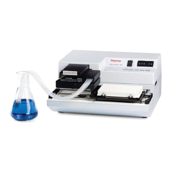
4.2 Multidrop 384 microplate dispenser The Multidrop 384 microplate dispenser (Fig. 4.6) automates dispensing into microplates. The microprocessor-based system permits volumes between 5 ― 100 µl for 384-well plates and 5 ― 395 µl for 96-well plates to be selected (in 5 µl increments) and then dispensed simultaneously into eight wells (one column of a 96-well microplate). -
Page 17: Installation
5.2 What to do upon delivery 5.2.1 How to unpack Move the unpacked instrument to its site of operation. Unpack the Multidrop 384 instrument and accessories carefully with the arrows on the transport package pointing upwards. The following notes and instructions are sent with the instrument and are immediately available when you open the package: •... -
Page 18: Checking For Damage During Transport
Leave sufficient space (at least 10 cm) on both sides and at the back of the unit to allow adequate air circulation. The Multidrop 384 does not produce operating noise at a level that would be harmful. No sound level measurements are required after installation. -
Page 19: Setups Before You Put The Instrument Into Operation
Check that the voltage selector switch (Fig. 5.2) is in the correct position, that is, the voltage selected corresponds to the local voltage. Voltage Fig. 5.2 Location of the voltage selector ® Thermo Scientific Multidrop 384 User Manual; Rev. 3.4, Cat. no. 1507010... -
Page 20: How To Ensure Startup
Warning: Never operate your instrument from a power outlet that has no ground connection. Never use a mains supply cable other than the Thermo Scientific mains supply cable designed for your region. Fig. 5.3 Connecting the mains supply cable ®... -
Page 21: Operational Check
Terminates the operation and returns the plate to the home position For more information on the control panel, refer to section 6.5 How to use the control panel. ® Thermo Scientific Multidrop 384 User Manual; Rev. 3.4, Cat. no. 1507010... -
Page 22: Operating Precautions And Limitations Before Operation
Read this manual in its entirety, as it contains information necessary to ensure safe operation. Always ensure that the local supply voltage in the laboratory conforms to that specified on the type label on the back of the instrument. ® Thermo Scientific Multidrop 384 User Manual; Rev. 3.4, Cat. no. 1507010... -
Page 23: Routine Operation
6.2 Switching on Switch on the instrument by using the mains switch on the left-hand side of the instrument (Fig. 4.2). power The green LED will light up. ® Thermo Scientific Multidrop 384 User Manual; Rev. 3.4, Cat. no. 1507010... -
Page 24: How To Insert The Priming Vessel And The Dispensing Cassette
Take the lower part of the cassette into your right hand with the dispensing tips pointing down and the upper part into your left hand (Fig. 6.2). Fig. 6.2 Inserting the standard tube dispensing cassette ® Thermo Scientific Multidrop 384 User Manual; Rev. 3.4, Cat. no. 1507010... -
Page 25: Fig. 6.3 Inserting The Lower Part Of The Dispensing Cassette Into Its Slots
(Fig. 6.4 and Fig. 4.1). Fig. 6.4 Inserting the upper part of the dispensing cassette ® Thermo Scientific Multidrop 384 User Manual; Rev. 3.4, Cat. no. 1507010... -
Page 26: Fig. 6.5 Lower And Upper Parts Of The Dispensing Cassette Inserted Evenly Into Their Slots
The microswitch controls that the cover is properly placed over the rotor. The Multidrop 384 is now ready for priming. Fig. 6.6 Pulling the rotor cover over the rotor ®... -
Page 27: How To Insert And Adjust The Plate Adapter
Note: Keep the dispensing cassette in the rest position when the dispensing cassette is not in use. 6.4 How to insert and adjust the plate adapter The Multidrop 384 requires a plate adapter for the plate carrier to function. Two different plate adapters are included (Fig. 6.7). The PLATE ADAPTER, PLATE HEIGHT MAX. -
Page 28: Fig. 6.8 Opening The Plate Adapter Lock
Take the plate adapter in your left hand and lower the right end. Place the plate adapter into the right end corner of the plate carrier (Fig. 6.9). Plate adapter lock Fig. 6.9 Placing the right end of the plate adapter ® Thermo Scientific Multidrop 384 User Manual; Rev. 3.4, Cat. no. 1507010... -
Page 29: Fig. 6.10 Pressing The Left End Of The Plate Adapter
Lock the plate adapter into place with the plate adapter lock located in the front left corner of the plate carrier (Fig. 6.11). Fig. 6.11 Closing the plate adapter lock ® Thermo Scientific Multidrop 384 User Manual; Rev. 3.4, Cat. no. 1507010... -
Page 30: Fig. 6.12 Loosening The Screws On The Right Of The Plate Carrier
Then loosen the two attached plastic-covered screws at the front of the plate adapter (Fig. 6.13). Fig. 6.13 Loosening the screws at the front of the plate adapter ® Thermo Scientific Multidrop 384 User Manual; Rev. 3.4, Cat. no. 1507010... -
Page 31: Fig. 6.14 Fastening The Front Screws Of The Plate Adapter
Fig. 6.15 Fastening the screws to the right of the plate carrier Note: Ensure the dispensing cassette is attached and the rotor cover has been pulled over the rotor. ® Thermo Scientific Multidrop 384 User Manual; Rev. 3.4, Cat. no. 1507010... -
Page 32: How To Use The Control Panel
6.5 How to use the control panel The keypad has an embossed, tactile membrane with five keys. There are two control panel indicators (LEDs) in all. The control panel is shown in Fig. 6.16. Fig. 6.16 Multidrop 384 control panel 6.5.1 Control panel indicators power power The green LED indicates that the dispenser is powered. -
Page 33: Control Panel Keys
12 in the 96 mode, the red light will light up and the dispensing operation will be terminated. Fig. 6.17 Multidrop 384 control panel ® Thermo Scientific Multidrop 384 User Manual; Rev. 3.4, Cat. no. 1507010... -
Page 34: How To Prime
Use the tubing weight provided if possible. Check that the priming vessel is firmly inserted next to the plate carrier. The Multidrop 384 will not operate if the priming vessel is not completely inserted into its slot. -
Page 35: How To Dispense Manually Into The Specified Column(S)
Press the key. The Multidrop 384 will now automatically dispense the preselected volume of reagent into the preselected number of columns. When dispensing has been completed, the plate carrier will automatically return to its home position. start Now you can dispense any number of plates by only changing the plate and pressing Note: Check that there is always enough liquid in the reservoir and ensure that all the tube ends are below the liquid level. -
Page 36: After Use
After washing, store the dispensing cassette in the rest position (Fig. 6.18). Note: Keep the dispensing cassette in the rest position when the dispensing cassette is not in use. Fig. 6.18 Rest position of the dispensing cassette ® Thermo Scientific Multidrop 384 User Manual; Rev. 3.4, Cat. no. 1507010... -
Page 37: Shutdown
After washing, store the dispensing cassette in the rest position (Fig. 6.18). Switch the Multidrop 384 off by pressing the mains switch (Fig. 4.2) at the end of the left side panel of the instrument into the OFF position. -
Page 38: Maintenance
The dispensing cassette is autoclavable. Do not autoclave any other part of this instrument. 7.1.2 Immediate Although the Multidrop 384 is constructed from high-quality materials, you must immediately wipe away spilled saline solutions, solvents, acids or alkaline solutions from outer surfaces to prevent damage and wipe with deionized distilled water. -
Page 39: How To Wash The Dispensing Cassette
The autoclaving conditions of the dispensing cassette are as follows: 1 bar pressure at 121°C for 20 minutes. Note: After autoclaving, the dispensing cassette must cool down to room temperature before use. ® Thermo Scientific Multidrop 384 User Manual; Rev. 3.4, Cat. no. 1507010... -
Page 40: How To Replace The Fuses
Remove the fuse holder cap with a screwdriver or similar tool. Press both ends of the fuse holder cap with the tool (Fig. 7.1 and Fig. 7.2). Fig. 7.1 Removing the fuse holder cap (A) Fig. 7.2 Removing the fuse holder cap (B) ® Thermo Scientific Multidrop 384 User Manual; Rev. 3.4, Cat. no. 1507010... -
Page 41: Fig. 7.3 Fuse Holder Cap With Fuses
Replace the blown fuse with the same type and push the fuse holder cap back into its position (Fig. 7.4). Fig. 7.4 Inserting the fuse holder cap Reconnect to the mains input socket and switch the power on. ® Thermo Scientific Multidrop 384 User Manual; Rev. 3.4, Cat. no. 1507010... -
Page 42: How To Recalibrate The Dispensing Cassette
1. Remove the priming vessel and microplate. 2. Install the dispensing cassette into the Multidrop 384 if it is not already installed. Place the dispensing cassette into the rest position (Fig. 6.18). Refer to section 6.3 How to insert the priming vessel and the dispensing cassette. -
Page 43: Fig. 7.6 Adjusting The Liquid Level First To The Lower Mark And Then To The Upper Mark
9. Press the keys at the same time. After that first release the prime/drop and then the key. This brings the Multidrop 384 into the volumetric calibration mode. start 10. Press the key as many times until the water enters the calibration pipette. -
Page 44: Gravimetric Calibration
15. Change the tube to the next channel and repeat Steps 10 to 14. stop 16. After all the channels have been recalibrated, press the key to reset the Multidrop 384 into normal operation and reinstall the priming vessel. 17. Close the calibration screw cover. - Page 45 Place the tube of channel A into the reservoir with water at room temperature (working temperature). Use 8 x 12 well microstrips and adjust the Multidrop 384 for 100 µl in 10 columns and set the plate plate switch ( ) for 96-well plates (Fig.
-
Page 46: Fig. 7.9 Removing The Filled Microstrip To Be Weighed
Fig. 7.10 Screwing the calibration screw according to the calibration results 13. Continue in the same way with each channel until all eight channels have been recalibrated. 14. Close the calibration screw cover. ® Thermo Scientific Multidrop 384 User Manual; Rev. 3.4, Cat. no. 1507010... -
Page 47: How To Change The Tubing Set
Then detach the tip band from the tubing by pulling the tubes away from the tip band (Fig. 7.12). Fig. 7.12 Removing the old tip band ® Thermo Scientific Multidrop 384 User Manual; Rev. 3.4, Cat. no. 1507010... -
Page 48: Fitting The New Tubing Set Step By Step
First place the new tubing set onto the laboratory bench with the tip band attached (Fig. 7.15). Ensure that you have saved the eight calibration screws and the tubing weight from the previous tubing set. ® Thermo Scientific Multidrop 384 User Manual; Rev. 3.4, Cat. no. 1507010... -
Page 49: Fig. 7.15 New Tubing Set With The Tip Band Attached
(Fig. 7.17). Ensure that each tube is in its designated opening (Fig. 7.18). Tip band Tube fasteners Fig. 7.16 Inserting the tip manifold into the lower part of the dispensing cassette ® Thermo Scientific Multidrop 384 User Manual; Rev. 3.4, Cat. no. 1507010... -
Page 50: Fig. 7.17 Pressing The Tube Fasteners Into Place
Fig. 7.18 New tubing inserted into the lower part of the dispensing cassette Attach the tension limiting wires into their slots (Fig. 7.19). Slots for tension limiting wires Fig. 7.19 Tension limiting wires attached ® Thermo Scientific Multidrop 384 User Manual; Rev. 3.4, Cat. no. 1507010... -
Page 51: Fig. 7.20 Replacing The Lower Part Cover Of The Dispensing Cassette
Once the lower part of the dispensing cassette has been fitted, place the remaining parts belonging to the upper part of the dispensing cassette onto the laboratory bench (Fig. 7.21). Fig. 7.21 Parts belonging to the upper part of the dispensing cassette ® Thermo Scientific Multidrop 384 User Manual; Rev. 3.4, Cat. no. 1507010... -
Page 52: Fig. 7.22 Placing The Sight Window
After that press the white tubing identification plate into place on the right-hand side of the bottom cover of the upper part of the dispensing cassette (Fig. 7.23). Fig. 7.23 Pressing the tubing identification plate into place ® Thermo Scientific Multidrop 384 User Manual; Rev. 3.4, Cat. no. 1507010... -
Page 53: Fig. 7.24 Pressing The Tube Fasteners Into Place
Fig. 7.24 Pressing the tube fasteners into place 10. Fasten the calibration screws from the previous tubing into their places using a hexagonal screwdriver (Fig. 7.25). Fig. 7.25 Fastening the calibration screws ® Thermo Scientific Multidrop 384 User Manual; Rev. 3.4, Cat. no. 1507010... -
Page 54: Fig. 7.26 Calibration Screws Fastened
13. Ensure you do not get the tubing trapped or bent between the bottom and upper cover of the upper part of the dispensing cassette (Fig. 7.28). Fig. 7.28 Ensuring the tubing does not get trapped ® Thermo Scientific Multidrop 384 User Manual; Rev. 3.4, Cat. no. 1507010... -
Page 55: Fig. 7.29 Fastening The Cover Retaining Screws
Fig. 7.29 Fastening the cover retaining screws 15. Insert the calibration screw cover easier by lifting or bending the upper cover slightly (Fig. 7.30). Fig. 7.30 Inserting the plate on the calibration screws ® Thermo Scientific Multidrop 384 User Manual; Rev. 3.4, Cat. no. 1507010... -
Page 56: Fig. 7.31 Lower And Upper Part Of The Dispensing Cassette Fitted
16. Fasten the front cover retaining screw (Fig. 7.31). Continued below. Fig. 7.31 Lower and upper part of the dispensing cassette fitted ® Thermo Scientific Multidrop 384 User Manual; Rev. 3.4, Cat. no. 1507010... -
Page 57: Fig. 7.32 Dispensing Cassette Before Precalibration
(Fig. 7.33). Sight Fig. 7.32 Dispensing cassette before precalibration Fig. 7.33 Precalibrating the dispensing cassette ® Thermo Scientific Multidrop 384 User Manual; Rev. 3.4, Cat. no. 1507010... -
Page 58: Fig. 7.34 Dispensing Cassette Precalibrated
Fig. 7.35 Inserting the tubes into the tubing weight 20. Calibrate the dispensing cassette according to the instructions in section 7.5 How to recalibrate the dispensing cassette. ® Thermo Scientific Multidrop 384 User Manual; Rev. 3.4, Cat. no. 1507010... -
Page 59: Disposal Of Materials
Place a wad of cotton wool soaked in the prepared solution into the bag. Ensure that the wad does not make contact with the instrument. ® Thermo Scientific Multidrop 384 User Manual; Rev. 3.4, Cat. no. 1507010... -
Page 60: How To Pack For Service
Dispose of the instrument according to the legislation stipulated by the local authorities concerning take-back of electronic equipment and waste. The proposals for the procedures vary by country. ® Thermo Scientific Multidrop 384 User Manual; Rev. 3.4, Cat. no. 1507010... - Page 61 Further information on Thermo Fisher Scientific’s compliance with these Directives, the recyclers in your country, and information on Thermo Scientific products which may assist the detection of substances subject to the RoHS Directive are available at www.thermo.com/WEEERoHS.
-
Page 62: Technical Specifications
100 µl: ≤ 1% (typical) Valid when counted for the entire plate * using the calibration procedure in section 7.5 the accuracy can be improved to ± 1.5% ® Thermo Scientific Multidrop 384 User Manual; Rev. 3.4, Cat. no. 1507010... -
Page 63: Safety Specifications
Voltages dangerous for human beings are present in this instrument. Before removing any covers, disconnect the instrument from the power supply. The Multidrop 384 fulfils the following requirements: EN 61010-1:1993 + A2:1995/IEC 61010-1:1990 + A1:1992 + A2:1995 taking into account US and CA National differences EN 61010-1:2001 (Ed. -
Page 64: In Conformity With The Requirements
Type 832 100 ― 120 Vac, 200 ― 240 Vac 50/60 Hz, 50 VA CE mark CSA monogram The Multidrop 384 conforms to the following requirements: 2006/95/EC (Low Voltage Directive) 2004/108/EC (Electromagnetic Compatibility Directive, EMC) FCC Part 15, Subpart B/Class B... -
Page 65: Remote Control To Multidrop 384
XON/XOFF Commands Commands to the Multidrop 384 have two to three fields as described in the following syntax. The first letter identifies the command. Then a numeric argument field is optional for some and required for other commands. The numeric field immediately follows the uppercase letter without any separating characters. - Page 66 5 to 1000 µl. For a 384-well plate the range is 5 to 140 µl. The volume must be dispensed in 5 µl increments. Zs<LF> Shake the plate the desired amount of time. The time is seconds and may range from 1 to 60. ® Thermo Scientific Multidrop 384 User Manual; Rev. 3.4, Cat. no. 1507010...
- Page 67 ER3<CR><LF> Unrecognized command or invalid command argument. ER4<CR><LF> The pump is not primed. ER5<CR><LF> The priming vessel is not inserted into its slot. ER6<CR><LF> Hardware error. The instrument stops and must be reset manually. ® Thermo Scientific Multidrop 384 User Manual; Rev. 3.4, Cat. no. 1507010...
-
Page 68: Troubleshooting
The priming vessel is not present. Insert the priming vessel. error operates when trying There is dirt in the priming vessel Clean the priming vessel sensor. prime sensor. ® Thermo Scientific Multidrop 384 User Manual; Rev. 3.4, Cat. no. 1507010... -
Page 69: Faqs About The Multidrop 384
9.2 FAQs about the Multidrop 384 Q1: Can the same dispensing cassette be used in all Multidrop models? A1: No, use only dispensing cassettes designed for Multidrop 384. It is not possible to use small tube dispensing cassettes. Q2: How many times can the dispensing cassette be autoclaved? A2: Fifty times. -
Page 70: Hazards
Hand and eye protections should always be worn as well as corrosive resistant laboratory coats. Observe normal laboratory procedures for handling potentially hazardous samples. ® Thermo Scientific Multidrop 384 User Manual; Rev. 3.4, Cat. no. 1507010... -
Page 71: Defects And Abnormal Stresses
9.4 Service request protocol If the Multidrop 384 requires service, contact your local Thermo Fisher Scientific representative or the Thermo Fisher Scientific technical service department. Do not under any circumstances send the instrument for service without any prior contact. It is imperative to indicate the fault and nature of the required service. -
Page 72: Certificate Of Decontamination
*) The signature of a Radiation Safety Officer is also required when the unit has been used with radioactive materials. This unit is certified by the undersigned to be free of radioactive contamination. Date and place Signature Name (block capitals) PHOTOCOPIABLE Please include decontaminating solution used. ® Thermo Scientific Multidrop 384 User Manual; Rev. 3.4, Cat. no. 1507010... -
Page 73: Warranty Certificate
These warranty terms and conditions can be obtained from your local Thermo Fisher Scientific dealer. Note: Consumables are not included in the warranty. ® Thermo Scientific Multidrop 384 User Manual; Rev. 3.4, Cat. no. 1507010... -
Page 74: Ordering Information
11 ORDERING INFORMATION 11.1 Instruments Code Instrument 5840150 Multidrop 384, 220 – 240 V 50/60 Hz 5840157 Multidrop 384, 110 – 120 V 50/60 Hz 11.2 Dispensing cassettes Code Dispensing cassette 24072670 Standard tube dispensing cassette (with 40 cm tubing set) -
Page 75: Spare Parts For Dispensing Cassettes
1046241 Priming vessel, eight cavities 10260315 Self-draining priming vessel 11.5 List of accessories Code Item 1507010 Multidrop 384 User Manual 2406910 Volumetric calibration device 1610641 Dust cover 24071790 Plate adapter (max. 15 mm height) 24071800 Plate adapter (max. 11 mm height) -
Page 76: List Of Spare Parts
Fuse 0.6 A slow 5 x 20 (115 V) 1210850 Fuse 0.3 A slow 5 x 20 (230 V) 2003350 MUKEY PCB 2004330 MUDROP-03 PCB 2004340 MUBCD-02 PCB (384) 2304720 Microswitch assembly 2304860 Flat cable ® Thermo Scientific Multidrop 384 User Manual; Rev. 3.4, Cat. no. 1507010... -
Page 77: Glossary And Abbreviations
The plate carrier is positioned to the furthest right of the transfer rails (Fig. 4.1). home position International Electrotechnical Commission The Multidrop 384 requires a plate adapter for the plate carrier to function. plate adapter Two different plate adapters are included: the PLATE HEIGHT MAX. -
Page 78: Keywords For Web
12.1 Keywords for web pages automated dispensers microwell plate automated fluid dispensing multidispense automated liquid handling multidrop dispensing Multidrop drug discovery Multidrop 384 multidrops ELISA plate enzyme immunoassay robotic platform immunoassay sandwich assay liquid handling separation technique(s) microplate solid phase assay(s) -
Page 79: Index
13 INDEX Abbreviations............................75 Accessories ..........................15, 16, 73 Addresses ............................. 85 Advantages of using the Multidrop 384....................9 Application ........................... 5, 6, 9, 76, 84 Bottle ............................... 9 Cable ....................15, 17, 18, 19, 57, 61, 68, 73, 74, 81 Calibration .........12, 24, 32, 33, 40, 41, 42, 43, 44, 46, 47, 51, 52, 53, 55, 60, 73, 81, 82... - Page 80 Mode..........................14, 31, 32, 33, 41 Multidrop 384..7, 8, 9, 10, 11, 12, 13, 14, 15, 16, 24, 25, 30, 31, 32, 33, 35, 36, 40, 41, 42, 43, 61, 62, 63, 67, 69, 72, 73, 74, 75, 76, 81, 82, 83 Operating precautions and limitations....................
- Page 81 Specifications ........................7, 29, 60, 61 general ............................... 60 safety ..............................61 Startup ............................18, 21, 64 Step ......................14, 19, 31, 33, 35, 41, 46, 60 Switching on ............................18 Symbols..............................6 ® Thermo Scientific Multidrop 384 User Manual; Rev. 3.4, Cat. no. 1507010...
- Page 82 Volumetric calibration ....................32, 33, 40, 41, 60, 73 Warnings ........................... 16, 17, 18 Warranty ............................7, 15, 71 Weight ....................12, 16, 32, 33, 46, 47, 56, 60, 73 ® Thermo Scientific Multidrop 384 User Manual; Rev. 3.4, Cat. no. 1507010...
-
Page 83: Table Of Figures
ASTENING THE CALIBRATION SCREWS . 7.26 C ....................52 ALIBRATION SCREWS FASTENED . 7.27 R ........ 52 EPLACING THE COVER OF THE UPPER PART OF THE DISPENSING CASSETTE ® Thermo Scientific Multidrop 384 User Manual; Rev. 3.4, Cat. no. 1507010... - Page 84 . 7.35 I ................ 56 NSERTING THE TUBES INTO THE TUBING WEIGHT . 11.1 D ................72 ISPENSING CASSETTE ACHINED COVERS 1. 1 M ................83 PPENDIX ULTIDROP CONTROL PANEL ® Thermo Scientific Multidrop 384 User Manual; Rev. 3.4, Cat. no. 1507010...
-
Page 85: Appendix 1. Thermo Scientific Multidrop 384 Brief User'sguide
(p. 34). • Put the dispensing cassette into the rest position (p. 34). • Maintain your Multidrop 384 instrument and dispensing cassette (p. 36). • Switch off the instrument (p. 35). Fig. Appendix 1. 1 Multidrop 384 control panel ®... -
Page 86: Appendix 2. Thermo Scientific Multidrop 384 Feedback Form
Customer support Further instrument/system developments desired: Further applications desired: Where did you first learn about the product? Would you like to receive information about other Thermo Scientific products? ® Thermo Scientific Multidrop 384 User Manual; Rev. 3.4, Cat. no. 1507010... -
Page 87: Appendix 3. Addresses
For the latest information on products and services, visit our websites at: http://www.thermo.com http://www.thermo.com/multidrop Manufactured by: Distributed by: Thermo Fisher Scientific Oy P.O. Box 100, FI-01621 Vantaa, Finland Tel. +358-9-329 100, Fax +358-9-3291 0415 www.thermo.com ® Thermo Scientific Multidrop 384 User Manual; Rev. 3.4, Cat. no. 1507010... - Page 88 ® Thermo Scientific Multidrop 384 User Manual; Rev. 3.4, Cat. no. 1507010...
- Page 89 ® Thermo Scientific Multidrop 384 User Manual; Rev. 3.4, Cat. no. 1507010...
- Page 90 ® Thermo Scientific Multidrop 384 User Manual; Rev. 3.4, Cat. no. 1507010...
- Page 92 Thermo Fisher Scientific Oy Microplate Instrumentation Ratastie 2, P.O. Box 100 FI-01621 Vantaa Finland www.thermo.com 15017010...
Need help?
Do you have a question about the Multidrop 384 and is the answer not in the manual?
Questions and answers