
Related Manuals for CAME BK-221


Summary of Contents for CAME BK-221
- Page 1 FA01130M04 Automazione per cancelli scorrevoli IT Italiano EN English BK-221 FR Français RU Русский MANUALE DI INSTALLAZIONE...
- Page 2 GNI ALTRO USO È DA CONSIDERARSI PERICOLOSO ’ PASSARE UN OGGETTO DAVANTI DURANTE LA CHIUSURA SE L AUTOMAZIONE INVERTE CAME S. NON È RESPONSABILE PER EVENTUALI DANNI CAUSATI DA USI IMPROPRI • C IL SENSO DI MARCIA O SI BLOCCA LE FOTOCELLULE FUNZIONANO CORRETTAMENTE...
- Page 3 L’automazione è stata progettata per motorizzare cancelli scorrevoli per uso condominiale o industriale. Ogni installazione e uso diff ormi da quanto indicato nel seguente manuale sono da considerarsi vietate. Limiti d’impiego Tipo BK-221 Peso max. anta (kg) 2.200 Lunghezza max. anta (m)
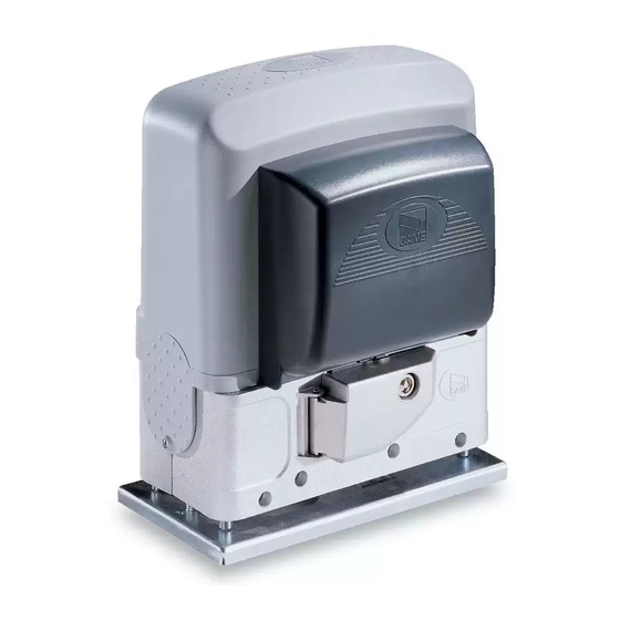
- Page 4 Descrizione delle parti 1. Coperchio 7. Alette di finecorsa 2. Motoriduttore 8. Finecorsa meccanico 3. Scheda elettronica 9. Ventola 4. Coperchio frontale 10. Trasformatore 5. Piastra di fissaggio 11. Sportello di sblocco 6. Porta-scheda elettronica 12. Chiave di sblocco Impianto tipo 1.
- Page 5 INDICAZIONI GENERALI PER L'INSTALLAZIONE ⚠ L’installazione deve essere effettuata da personale qualificato ed esperto e nel pieno rispetto delle normative vigenti. Verifiche preliminari ⚠ Prima di procedere all’installazione dell’automazione è necessario: • controllare che il cancello sia stabile e che le ruote di scorrimento siano in buono stato e ingrassate; •...
-
Page 6: Installazione
INSTALLAZIONE ⚠ Le seguenti illustrazioni sono solo esempi in quanto lo spazio per il fissaggio dell’automazione e degli accessori varia a seconda degli ingombri. Spetta all’installatore scegliere la soluzione più adatta. I disegni si riferiscono all’automazione installata a sinistra. Posa dei tubi corrugati Fare lo scavo per la cassa matta. - Page 7 Nel caso in cui la cremagliera sia già presente, posizionare la piastra di fissaggio rispettando le misure riportate sul disegno. Attenzione! I tubi devono passare attraverso i fori predisposti. Riempire la cassa matta di cemento, la piastra deve essere perfettamente in bolla e con il filetto delle viti completamente in superficie. Attendere che si solidifichi per almeno 24h.
- Page 8 Preparazione del motoriduttore Rimuovere il coperchio frontale e il coperchio del motoriduttore. Posizionare il motoriduttore sopra la piastra di fissaggio. Attenzione! I cavi elettrici devono passare sotto la cassa del motoriduttore. Sollevare il motoriduttore di 5÷10 mm dalla piastra agendo sui piedini filettati per permettere eventuali regolazioni successive tra pignone e cremagliera.
- Page 9 Fissaggio della cremagliera Se la cremagliera c’è già, procedere direttamente alla regolazione della distanza di accoppiamento pignone-cremagliera, altrimenti procedere con il fissaggio: - sbloccare il motoriduttore (vedi paragrafo SBLOCCO DEL MOTORIDUTTORE); - appoggiare la cremagliera sopra il pignone del motoriduttore; - saldare o fissare la cremagliera al cancello in tutta la sua lunghezza.
- Page 10 Fissaggio del motoriduttore Completata la regolazione, fissare il motoriduttore alla piastra con gli scontri e i dadi. Determinazione dei punti di finecorsa In apertura: - aprire il cancello - infi lare l’aletta di fi necorsa di apertura sulla cremagliera fi no a far scattare il micro (molla) e fi ssarla con i grani Molla ~ 20 mm In chiusura:...
-
Page 11: Collegamenti Elettrici
COLLEGAMENTI ELETTRICI ⚠ Attenzione! Prima di intervenire sulla scheda elettronica, togliere la tensione di linea e, se presenti, scollegare le batterie. Le funzioni sui contatti di ingresso e uscita, le regolazioni dei tempi e la gestione degli utenti, vengono impostate e visualizzate sul display grafico. Tutte le connessioni sono protette da fusibili rapidi. - Page 12 Alimentazione Per variare la coppia motore, spostare il faston indicato su una delle Rosso 4 posizioni; da 1 (min) a 4 (max). 230 V AC 50/60 Hz Grigio Nero Bianco Marrone Viola Arancione Uscita alimentazione accessori 24 V AC - max 37 W L1T L2T CT VS VF V W E EX...
- Page 13 Dispositivi di segnalazione Uscita collegamento di un lampeggiatore (portata contatto: 230 V AC - 25 W max) o abbinato con una lampada ciclo (Portata contatto: 230 V - 60 W max). Vedi funzione [Uscita lampada] nel menu [FUNZIONI]. Uscita segnalazione cancello aperto (portata contatto 24 V AC - 3 W max).
- Page 14 Bordi sensibili Configurare il contatto CX o CY (NC), ingresso per dispositivi di sicurezza tipo bordi sensibili, conformi alla normativa EN 12978. Vedi funzioni [ingresso C7] o [ingresso C8] in: - C7 riapertura durante la chiusura. In fase di chiusura del cancello, l’apertura del contatto provoca l’inversione del movimento fino alla completa apertura;...
- Page 15 PROGRAMMAZIONE Descrizione dei comandi di programmazione I tasti < > servono per: - spostarsi da una voce di menu a un’altra; - incrementare o decrementare un valore. Il tasto ESC serve per: LINGUA - uscire dai menu; - annullare le modifiche. <...
- Page 16 Significato delle abbreviazioni sulle voci di menu [Ap. parziale] Apertura Parziale [Az. Mantenuta] Azione Mantenuta [Az. Mant.Chiude] Azione Mantenuta Chiude [Ch. Automatica] Chiusura Automatica [Ind. rete] Indirizzo rete [Lampegg.] Lampeggiatore [Modifica Ut] Modifica Utente [Msg. iniziale] Messaggio iniziale [Ril ostacolo] Rilevazione Ostacolo [Rimuovi Ut.] Rimuovi Utente...
- Page 17 IMPORTANTE! Iniziare la programmazione eseguendo per prime le funzioni [STOP TOTALE] e [TARATURA CORSA] Menu lingua [LINGUA] [Italiano] / [English] / [Français] / [Deutsch] / [Español] Selezionare la lingua tra quelle disponibili Menu funzioni [FUNZIONI] [Ch. Automatica] [ON] / [OFF] L’attesa prima della chiusura automatica parte dal raggiungimento del punto di fi...
- Page 18 Menu regola tempi [REGOLA TEMPI] [T.C.A.] [0 s] ⇨ [120 s] L’attesa prima della chiusura automatica parte dal raggiungimento del punto di fi necorsa in apertura per un tempo regolabile da 0 s a 120 s. La chiusura automatica non si attiva nel caso in cui intervengano i dispositivi di sicurezza per la rilevazione di un ostacolo, dopo uno stop totale o in caso di mancanza di tensione.
- Page 19 [Ap. parziale] [10%] ⇨ [80%] Regolazione del punto di apertura parziale del cancello. Il punto di apertura parziale è calcolato in percentuale (da 10% a 80% della corsa completa). [ENCODER] [ON] / [OFF] Gestione dei rallentamenti, della rilevazione degli ostacoli e della sensibilità. Con ENCODER disattivato, la scheda lavora solo con i finecorsa meccanici.
- Page 20 Modifica utente (mofifica della funzione) 2. Selezionare il numero utente di cui si vuole 1. Dal menu [RADIO UTENTI], selezionare modificare la funzione associata. Premere ENTER [Modifica Ut.]. Premere ENTER per confermare. per confermare. Modifica Ut. < Modifica Ut. > <n.001 Utilizzato>...
- Page 21 Scheda Memory Roll Per memorizzare i dati relativi agli utenti e alla configurazione dell’impianto, per poi riutilizzarli con un’altra scheda elettronica. Dopo aver memorizzato i dati, è consigliabile togliere la Memory Roll durante il funzionamento della scheda elettronica. L1T L2T CT VS VF V W E EX 26V 17V 0 10 11...
- Page 22 OPERAZIONI FINALI Le operazioni fi nali sono da eff ettuare a collegamenti terminati e messa in funzione. SBLOCCO DEL MOTORIDUTTORE ⚠ L’operazione deve essere eff ettuata in assenza di tensione. ⚠ Lo sblocco manuale dell’automazione può causare un movimento incontrollato del cancello, se questo presenta problemi meccanici o se non è...
-
Page 23: Messaggi Di Errore
MESSAGGI DI ERRORE I messaggi di errore appaiono a display. [Sblocco Attivo] Sportello di sblocco aperto [STOP Attivo] Contatto 1-2 (NC) aperto [Errore test servizi] Malfunzionamento dei dispositivi di sicurezza o collegamento errato [Tempo Lavoro] Tempo lavoro insufficiente [CX Attivo], [CY Attivo], [C7 Attivo] o [C8 Attivo] Contatti (NC) aperti RISOLUZIONE DEI PROBLEMI PROBLEMI... -
Page 24: Riferimenti Normativi
14001 a garanzia del rispetto e della tutela dell’ambiente. Vi chiediamo di continuare l’opera di tutela dell’ambiente, che CAME considera uno dei fondamenti di sviluppo delle proprie strategie operative e di mercato, semplicemente osservando brevi indicazioni in materia di smaltimento: SMALTIMENTO DELL’IMBALLO... - Page 25 FA01130-EN Sliding gate operator INSTALLATION MANUAL BK-221 English...
- Page 26 HIS PRODUCT SHOULD ONLY BE USED FOR THE PURPOSE FOR WHICH IT WAS EXPLICITLY DESIGNED • I THAT MAY RUIN THE DEVICES F REPAIRS OR MODIFICATIONS ARE REQUIRED TO THE . CAME S. NY OTHER USE IS DANGEROUS IS NOT LIABLE FOR ANY DAMAGE CAUSED BY SYSTEM RELEASE THE OPERATOR AND DO NOT USE IT UNTIL SAFETY CONDITIONS HAVE •...
- Page 27 The operator is designed to power sliding gates used in apartment blocks and industrial plants. Any installation and/or use other than that specifi ed in this manual is forbidden. Limits to use Type BK-221 Max gate-leaf weight (kg) 2.200 Maximum gate-leaf length (m)
- Page 28 Description of parts 1. Cover 7. Limit-switch fins 2. Gearmotor 8. Mechanical limit switch 3. Control board 9. Fan 4. Front cover 10. Transformer 5. Anchoring plate 11. Release hatch 6. Control-board holder 12. Release key Standard installation 1. Operator 7.
- Page 29 GENERAL INSTALLATION INDICATIONS ⚠ Only skilled, qualified staff must install this product. Preliminary checks ⚠ Before beginning the installation, do the following: • check that the gate is stable and that the casters are in good working order and lubricated; •...
-
Page 30: Installation
INSTALLATION ⚠ The following illustrations are mere examples in that the space for fastening the operator and accessories varies depending on the installation area. It is up to the installer to find the most suitable solution. The drawing show an operator fitted on the left. Corrugated tube laying Dig a hole for the foundation frame. - Page 31 If the rack is already there, place the anchoring plate, being careful to respect the measurements shown in the drawing. Careful! The tubes must pass through their corresponding holes. Fill the foundation frame with concrete. The plate must be perfectly level with the bolts which are entirely above surface. Wait at least 24 hrs for the concrete to solidify.
- Page 32 Setting up the gearmotor Remove the front cover and gearmotor cover. Place the gearmotor above the anchoring plate. Careful! The electric cables must pass under the gearmotor case. Raise the gearmotor by 5 to 10 mm from the plate by turning the threaded feet, to make room for further pinion and rack adjustments.
- Page 33 Fastening the rack If the rack is already set up, the next step should be to adjust the rack-and-pinion coupling distance, otherwise, fasten it: - release the gearmotor (see RELEASING THE GEARMOTOR paragraph); - rest the rack above the gearmotor pinion; - weld or fasten the rack to the gate along its entire length.
- Page 34 Fastening the gearmotor Once adjusting is complete, fasten the gearmotor to the plate using the plates and nuts. Establishing the limit-switch points For opening: - open the gate - fi t the opening limit-switch tab onto the rack until the micro switch activates (spring) and fasten it using the grub screws Spring ~ 20 mm For closing:...
-
Page 35: Electrical Connections
ELECTRICAL CONNECTIONS ⚠ Warning! Before doing any work on the control board, cut off the mains power supply, and disconnect any batteries. The functions on the input and output contacts, the time settings and user management, are set and viewed on the graphic display. All connections are quick-fuse protected. - Page 36 Power supply To vary the motor torque, move the shown faston to one of the four positions; from 1 (min.) to 4 (max.). 230 V AC 50/60 Hz Grey Black White Brown Blue Purple Orange Accessories power- supply output (24 AC - max.
- Page 37 Signaling devices Connection output for a flashing light (contact rated for: 230 V AC - 25 W max) or paired with a cycle lamp (Contact rated for: 230 V - 60 W max). See the [Lamp Output] in the [FUNCTIONS] menu. Gate open warning output (contact rated for: 24 V AC - 3 W max).
- Page 38 Sensitive Safety Edges Configure contact CX or CY (NC), input for safety devices, such as sensitive safety edges, that comply with EN 12978 provisions. See [C7 input] or [C8 input] in: - C7 reopening during closing. when the gate is closing, opening the contact causes the inversion of movement until opening is complete; - C8 reclosing during opening.
- Page 39 PROGRAMMING Description of programming commands The < > keys are for: - moving from one item to another; - increasing or decreasing values. The ESC button is for: LANGUAGE - exiting menus; - cancelling changes. < English > The ENTER key is for: - entering menus;...
- Page 40 Meaning of the menu items abbreviations [Partial Op.] Partial Opening [Maintained Act] Maintained Action [Maint.Act. Cl.] Maintained Action Close [Autom.Clos.] AutoClose [NET address] Network address [Fl. light] Flashing light [Modify User] Edit User [Standby Msg.] Starting message [Obst. Detec] Obstruction Detection [Remove Usr.] Remove User [Gate run sens]...
- Page 41 IMPORTANT! Start programming by first performing the [TOTAL STOP] and [TRAVEL CALIBRATION] functions Language menu [LANGUAGE] [Italiano] / [English] / [Français] / [Deutsch] / [Español] Select one of the available languages Functions menu [FUNCTIONS] [Autom. Clos.] [ON] / [OFF] The wait before the automatic closing starts when the opening end point is reached, and can be adjusted to between 1 s and 120 s. The automatic closing does not activate if any of the safety devices trigger when an obstruction is detected, or after a total stop, or during a power outage.
- Page 42 Time settings menu [TIMING ADJ.] [A.C.T.] [0 s] ⇨ [120 s] The wait before the automatic closing starts when the opening end point is reached, and can be adjusted to between 1 s and 120 s. The auto- matic closing does not turn on if any of the safety devices trigger when an obstruction is detected, after a total stop or during a power outage. [Cycle time] [10 s] ⇨...
- Page 43 [Partial op.] [10%] ⇨ [80%] Adjusting the gate's partial-opening point. The partial-opening point is calculated as a percentage (from 10% to 80% of the complete gate travel). [ENCODER] [ON] / [OFF] Managing slow-downs, obstruction detections and sensitivity. With the ENCODER deactivated, the control board only works with the mechanical stops. [NET address] [Desabled] / [Master] / [Slave] To set up the control board as the Master board or Slave when you have a paired connection.
- Page 44 Change user (edit the function) 2. Select the user number to change the associated 1. From the [RADIO USRS], select [Modify user]. function. Press ENTER to confirm. Press ENTER to confirm. < Modify User > Modify User <n.001 in use > Modify User <n.002 in use>...
- Page 45 Memory Roll Card For memorizinguser and system configuration data, then using them on another control board. After memorizing the data, it is best to remove the Memory Roll card while the control board is in operation. L1T L2T CT VS VF V W E EX 26V 17V 0 10 11...
-
Page 46: Final Operations
FINAL OPERATIONS Do the fi nal operation only once the connections are complete and the system is started up. RELEASING THE GEARMOTOR ⚠ This procedure must be done with the main power cut off . ⚠ Manually releasing the operator may result in uncontrolled movement of the gate, if this has any mechanical problems or is unbalanced. ⚠ ... -
Page 47: Error Message
ERROR MESSAGE Error messages appear on the display. [Release Active] Open release hatch door [STOP Active] Contact 1-2 (NC) open [Services test Error] Malfunctioning safety devices or wrong connection [Cycle Time] Insufficient working time [CX Active], [CY Active], [C7 Active] or [C8 Active] (NC) contacts open TROUBLESHOOTING ISSUES... -
Page 48: Dismantling And Disposal
__________________________________________________________________________________________ DISMANTLING AND DISPOSAL ☞ CAME S.p.A. applies a certified Environmental Management System at its premises, which is compliant with the UNI EN ISO 14001 standard to ensure the environment is safeguarded. Please continue safeguarding the environment. At CAME we consider it one of the fundamentals of our operating and market strategies. Simply... - Page 49 FA01130-FR Automatisme pour portails coulissants MANUEL D'INSTALLATION BK-221 Français...
- Page 50 OUR S ASSURER DU ÉTÉ EXPRESSÉMENT CONÇU OUTE AUTRE UTILISATION EST À CONSIDÉRER COMME BON FONCTIONNEMENT DES PHOTOCELLULES Y PASSER DEVANT UN OBJET DURANT . CAME S. DANGEREUSE DÉCLINE TOUTE RESPONSABILITÉ EN CAS D ÉVENTUELS LA FERMETURE SI L AUTOMATISME INVERSE LE SENS DE LA MARCHE OU QU...
- Page 51 L’automatisme a été conçu pour motoriser des portails coulissants à usage collectif ou industriel. Toute installation et toute utilisation autres que celles qui sont indiquées dans ce manuel sont interdites. Limites d’utilisation Type BK-221 Poids max. vantail (Kg) 2 200 Longueur max. vantail (m) Module pignon Données techniques...
- Page 52 Description des parties 1. Couvercle 7. Ailettes de fin de course 2. Motoréducteur 8. Fin de course mécanique 3. Carte électronique 9. Ventilateur 4. Couvercle frontal 10. Transformateur 5. Plaque de fixation 11. Volet de déblocage 6. Support de carte électronique 12.
- Page 53 INSTRUCTIONS GÉNÉRALES POUR L'INSTALLATION ⚠ L’installation doit être effectuée par du personnel qualifié et dans le plein respect des normes en vigueur. Contrôles préliminaires ⚠ Avant d'installer l'automatisme, il faut : • contrôler que le portail est stable et que les roues de guidage sont en bon état et bien lubrifiées ; •...
- Page 54 INSTALLATION ⚠ Les illustrations suivantes ne sont que des exemples étant donné que l'espace pour la fixation de l'automatisme et des accessoires varie en fonction des encombrements. C'est donc l'installateur qui doit choisir la solution la plus indiquée. Les dessins illustrent l'automatisme installé à gauche. Pose des gaines annelées Creuser la fosse pour le coffrage.
- Page 55 En présence de la crémaillère, positionner la plaque de fixation en respectant les dimensions indiquées sur le dessin. Attention ! Les tuyaux doivent passer à travers les trous prévus. Remplir le coffrage de ciment, la plaque doit être parfaitement nivelée et avec le filetage des vis totalement en surface. Attendre que le tout se solidifie pendant au moins 24 heures.
- Page 56 Préparation du motoréducteur Enlever le couvercle frontal et le couvercle du motoréducteur. Positionner le motoréducteur sur la plaque de fixation. Attention ! Les câbles électriques doivent passer sous le carter du motoréducteur. Soulever le motoréducteur de 5 à 10 mm de la plaque en intervenant sur les pieds filetés afin de permettre, par la suite, les éventuels réglages entre pignon et crémaillère.
- Page 57 Fixation de la crémaillère Si la crémaillère existe déjà, régler directement la distance d'accouplement pignon-crémaillère ou bien effectuer la fixation : - débloquer le motoréducteur (voir paragraphe DÉBLOCAGE DU MOTORÉDUCTEUR) ; - poser la crémaillère sur le pignon du motoréducteur ; - souder ou fixer la crémaillère au portail sur toute sa longueur.
- Page 58 Fixation du motoréducteur Au terme du réglage, fixer le motoréducteur à la plaque à l'aide des butées et des écrous. Détermination des points de fin de course En phase d'ouverture : - ouvrir le portail - enfi ler l'ailette de fi n de course d'ouverture sur la crémaillère jusqu'au déclic du micro-interrupteur (ressort) et la fi xer à l'aide des goujons Ressort ~ 20 mm En phase de fermeture :...
-
Page 59: Branchements Électriques
BRANCHEMENTS ÉLECTRIQUES ⚠ Attention ! Avant d'intervenir sur la carte électronique, mettre hors tension et déconnecter les éventuelles batteries. Les fonctions sur les contacts d'entrée et de sortie, les réglages des temps et la gestion des utilisateurs sont configurés et visualisés sur l'afficheur graphique. - Page 60 Alimentation Pour varier le couple moteur, déplacer la cosse indiquée sur l'une des Rouge Rouge 4 positions : de 1 (min.) à 4 (max.). 230 VAC 50/60 Hz Gris Noir Blanc Marron Bleu Violet Orange Sortie alimentation accessoires 24 VAC - max.
- Page 61 Dispositifs de signalisation Sortie connexion d'un feu clignotant (Portée contact : 230 VAC - 25 W max.) ou vis-à-vis avec une lampe cycle (Portée contact : 230 V - 60 W max.). Voir fonction [Sortie lampe] dans le menu [FONCTIONS]. Sortie signalisation portail ouvert (Portée contact 24 VAC - 3 W max.).
- Page 62 Bords sensibles Configurer le contact CX ou CY (NF), entrée pour dispositifs de sécurité, type bords sensibles, conformes à la norme EN 12978. Voir fonctions [entrée C7] ou [entrée C8] dans :- C7 réouverture durant la fermeture. Durant la phase de fermeture du portail, l'ouverture du contact provoque l'inversion du mouvement jusqu'à...
- Page 63 PROGRAMMATION Description des commandes de programmation Les touches < > permettent de/d' : - se déplacer d'une option de menu à l'autre - augmenter ou diminuer une valeur. La touche ESC permet de/d' : LANGUE - sortir des menus - annuler les modifications <...
- Page 64 Signification des abréviations sur les options de menu [Ouv. Partielle] Ouverture partielle [Action Maintenue] Action Maintenue [Act.Maint.Ferm.] Action Maintenue Fermeture [Ferm. Automat.] Fermeture Automatique [Ad. réseau] Adresse réseau [Feu Clign.] Feu clignotant [Modif. Utilis.] Modifier Utilisateur [Message Ini.] Message initial [Dét.
- Page 65 IMPORTANT ! Lancer la programmation en effectuant en premier les fonctions [ARRÊT TOTAL] et [AUTO-APP. COURSE] Menu langue [LANGUE] [Italiano] / [English] / [Français] / [Deutsch] / [Español] Sélectionner la langue parmi celles disponibles Menu fonctions [FONCTIONS] [Ferm. Automat.] [ON] / [OFF] L’attente avant la fermeture automatique démarre quand le point de fi...
- Page 66 Menu de réglage des durées [RÉGL. DURÉES] [T.C.A.] [0 s] ⇨ [120 s] L’attente avant la fermeture automatique démarre quand le point de fi n de course en phase d'ouverture est atteint. Cette attente peut être réglée entre 0 et 120 s. L'intervention des dispositifs de sécurité en cas de détection d'un obstacle, après un arrêt total ou à défaut de tension désactive la fermeture automatique.
- Page 67 [Ouv. Partielle] [10%] ⇨ [80%] Réglage du point d'ouverture partielle du portail. Le point d'ouverture partielle est calculé en pourcentage (de 10% à 80% de la course complète). [ENCODEUR] [ON] / [OFF] Gestion des ralentissements, de la détection des obstacles et de la sensibilité. Avec ENCODEUR désactivé, la carte fonctionne uniquement avec les butées de fin de course mécaniques.
- Page 68 Modification de l'utilisateur (modification de la fonction) 2. Sélectionner le nom d'utilisateur dont on souhaite 1. Dans le menu [RADIO UTILISA.], sélectionner modifier la fonction associée. Appuyer sur ENTER [Modif. Utilis.]. Appuyer sur ENTER pour confirmer. pour confirmer. < Modif. Utilisa. > Modif.
- Page 69 Carte de mémoire Pour mémoriserles données relatives aux utilisateurs et à la configuration de l'installation de manière à ce qu'elles soient réutilisables sur une autre carte électronique. Après avoir mémorisé les données, il est conseillé d'enlever la Memory Roll durant le fonctionnement de la carte électronique. L1T L2T CT VS VF V W E EX 26V 17V 0...
- Page 70 OPÉRATIONS FINALES Les opérations fi nales sont à eff ectuer au terme des connexions et après avoir contrôlé que tout fonctionne correctement, y compris le moteur. DÉBLOCAGE DU MOTORÉDUCTEUR ⚠ Mettre hors tension avant d'eff ectuer cette opération. ⚠ Le déblocage manuel de l'automatisme peut provoquer un mouvement incontrôlé du portail si ce dernier présente des problèmes mécaniques ou s'il n'est pas équilibré.
-
Page 71: Entretien
MESSAGES D'ERREUR Les messages d'erreur sont affichés à l'écran. [Déblocage Activé] Volet de déblocage ouvert [STOP Activé] Contact 1-2 (NF) ouvert [Erreur test services] Mauvais fonctionnement des dispositifs de sécurité ou branchement incorrect [Durée Fonctionn.] Temps de fonctionnement insuffisant [CX Activé], [CY Activé], [C7 Activé] ou [C8 Activé] Contacts (NF) ouverts RÉSOLUTION DES PROBLÈMES PROBLÈMES... - Page 72 _______________________________________________________________________________________________ MISE AU REBUT ET ÉLIMINATION ☞ CAME S.p.A. adopte dans ses établissements un Système de Gestion Environnementale certifié et conforme à la norme UNI EN ISO 14001 qui garantit le respect et la sauvegarde de l'environnement. Nous vous demandons de poursuivre ces efforts de sauvegarde de l'environnement, que CAME considère comme l'un des fondements du développement de ses propres stratégies opérationnelles et de marché, en observant tout simplement de brèves indications en matière d'élimination :...
- Page 73 FA01130-RU Автоматика для откатных ворот ИНСТРУКЦИЯ ПО МОНТАЖУ BK-221 RU Pусский...
- Page 74 ТО ИЗДЕЛИЕ ДОЛЖНО ИСПОЛЬЗОВАТЬСЯ ИСКЛЮЧИТЕЛЬНО ПО НАЗНАЧЕНИЮ С ЛЕДИТЕ ЗА ЧИСТОТОЙ И СМАЗКОЙ МЕХАНИЗМОВ ДВИЖЕНИЯ ПЕТЕЛЬ И Л . CAME ЮБОЕ ДРУГОЕ ПРИМЕНЕНИЕ РАССМАТРИВАЕТСЯ КАК ОПАСНОЕ ) • В СКОЛЬЖЕНИЯ НАПРАВЛЯЮЩИХ ЫПОЛНЯЙТЕ ФУНКЦИОНАЛЬНУЮ ПРОВЕРКУ СНИМАЕТ С СЕБЯ ВСЯКУЮ ОТВЕТСТВЕННОСТЬ ЗА ВОЗМОЖНЫЙ УЩЕРБ...
-
Page 75: Условные Обозначения
Привод предназначен для автоматизации откатных ворот в кондоминиумах и на промышленных объектах. Запрещается использовать устройство не по назначению и устанавливать его методами, отличными от описанных в настоящей инструкции. Ограничения в использовании Модель BK-221 Макс. масса створки (кг) 2 200 Макс. длина створки (м) Модуль шестерни... - Page 76 Основные компоненты 1. Крышка 7. Упоры концевых выключателей 2. Привод 8. Механический концевой выключатель 3. Плата блока управления 9. Вентилятор 4. Передняя крышка 10. Трансформатор 5. Монтажное основание 11. Дверца разблокировки 6. Держатель платы 12. Устройство разблокировки Вариант типовой установки 1.
- Page 77 ОБЩИЕ ИНСТРУКЦИИ ПО МОНТАЖУ ⚠ Монтаж должен производиться квалифицированным персоналом в полном соответствии с требованиями действующих норм безопасности. Предварительные проверки ⚠ Перед началом монтажных работ выполните следующее: • Проверьте, чтобы ворота были в устойчивом положении, колеса были в рабочем состоянии и смазаны. •...
- Page 78 МОНТАЖ ⚠ Приведенные ниже рисунки носят иллюстративный характер, так как пространство для установки автоматики и дополнительных принадлежностей может меняться от случая к случаю. Выбор наиболее подходящего решения должен осуществляться установщиком на месте. Рисунки иллюстрируют монтаж левосторонней автоматики. Прокладка гофрированных труб Выполните...
- Page 79 Если в системе уже предусмотрена зубчатая рейка, установите монтажное основание, соблюдая указанные на рисунке расстояния. Внимание! Трубы должны проходить через специально предусмотренные для этого отверстия. Заполните опалубку цементным раствором. Монтажное основание должно быть абсолютно ровным, резьба винтов должна находиться полностью на поверхности. Подождите...
- Page 80 Подготовка привода Снимите переднюю крышку и крышку привода. Установите привод на монтажное основание. Внимание! Электрические кабели должны проходить под корпусом привода. Приподнимите привод над монтажным основанием на 5-10 мм, используя стальные регулировочные шпильки, чтобы позднее произвести регулировку зацепления между шестерней и зубчатой рейкой.
- Page 81 Крепление зубчатой рейки Если зубчатая рейка уже предусмотрена, необходимо перейти непосредственно к регулировке расстояния в паре "зубчатое колесо - зубчатая рейка". - разблокируйте привод (смотрите раздел о разблокировке привода); - установите зубчатую рейку на шестерню привода; - приварите или прикрепите зубчатую рейку к воротам по всей длине. При...
- Page 82 Крепление привода По окончании регулировки зафиксируйте привод на монтажном основании с помощью гаек. Регулировка крайних положений При открывании: - откройте ворота - установите упор концевого выключателя открывания на зубчатую рейку так, чтобы он соприкасался с микровыключателем (пружиной), и зафиксируйте его винтами Пружина...
-
Page 83: Электрические Подключения
ЭЛЕКТРИЧЕСКИЕ ПОДКЛЮЧЕНИЯ ⚠ Внимание! Перед началом работ по эксплуатации, ремонту, настройке и регулировке платы управления отключите сетевое электропитание и/или отсоедините аккумуляторы. Установка функций входных/выходных контактов, режимов работы и регулировок осуществляется с помощью графического дисплея. Все подключения защищены плавкими предохранителями. Автоматика предназначена для левосторонней установки. В случае правосторонней установке поменяйте местами фазы ⚠... - Page 84 Электропитание Для изменения усилия привода установите указанную Красный ~230 В, 50/60 Гц клемму в одно из 4 положений: Серый 1 — минимальное усилие, 4 — Черный максимальное усилие. Белый Коричневый Синий Фиолетовый Оранжевый Контакты электропитания аксессуаров ~24 В, 37 Вт (макс.) L1T L2T CT VS VF V W E EX 26V 17V 0 10 11...
- Page 85 Устройства сигнализации Сигнальная лампа (макс. нагрузка контактов: ~230 В, макс. 25 Вт) или с лампой-цикла (макс. нагрузка контактов: ~230 В, макс. 60 Вт). Смотрите функцию [Lamp Output] в меню [FUNCTIONS]. Сигнализация "Ворота открыты" (макс. нагрузка контактов: ~24 В, макс. 3 Вт). V W E EX 26V 17V 0 10 11...
- Page 86 Чувствительные профили Выберите режим работы для контактов CX или CY (Н.З. контакты), предназначенных для подключения устройств безопасности, например, чувствительных профилей, соответствующих требованиям норматива EN 12978. Смотрите функции [C7 Input] или [C8 Input] в: - C7 "Открывание в режиме закрывания". Размыкание контактов во время закрывания ворот приводит к изменению направления движения...
- Page 87 ПРОГРАММИРОВАНИЕ Описание устройств программирования Кнопки < > служат для: - перемещения по меню; - увеличения или уменьшения значения выбранного параметра. Кнопка "ВЫХОД" (ESC) служит для: LANGUAGE - выхода из меню; < English > - отмены выбора. Кнопка "ВВОД" (ENTER) служит для: - входа...
- Page 88 Значение сокращений в пунктах меню [Partial op.] Частичное открывание [Maintained Act] Присутствие оператора [Maint. Act Cl.] Присутствие оператора - Только закрыть [Autom. Clos] Автоматическое закрывание [Net address] Сетевой адрес [Fl. light] Сигнальная лампа [Modify User] Изменить пользователя [Standby Msg] Приветственное сообщение [Obst.
- Page 89 ВАЖНО! Начните программирование с функций [STOP] и [GATE RUN ADJ] Меню «Язык» [LANGUAGE] [Italiano] / [English] / [Français] / [Deutsch] / [Español] Выберите желаемый язык из имеющихся в наличии. Меню "Функции" (FUNCTIONS) [FUNCTIONS] [Autom. Clos.] [ON] / [OFF] Отсчет времени автоматического закрывания начинается с момента достижения воротами концевого выключателя открывания. Время...
- Page 90 Меню регулировки времени [TIMING ADJ] [A.C.T.] [0 s] ⇨ [120 s] Отсчет времени автоматического закрывания начинается с момента достижения воротами концевого выключателя открывания. Время регулируется в диапазоне от 0 до 120 с. Функция автоматического закрывания блокируется, если в результате обнаружения препятствия срабатывают...
- Page 91 [Partial op.] [10%] ⇨ [80%] Регулировка точки частичного открывания ворот. Конечная точка частичного открывания определяется в процентном отношении (от 10 до 80%) от полного хода ворот. [ENCODER] [ON] / [OFF] Функция управления замедлением, обнаружением препятствий и чувствительностью системы защиты. Если функция "Encoder" отключена, плата управления работает только с механическими упорами. [NET address] [Disabled] / [Master] / [Slave] Для...
- Page 92 Изменение пользователя (изменение функции) 2. Выберите номер пользователя, присвоенную 1. В меню [RADIO USRS] выберите [Modify функцию которого вы хотите изменить. User]. Подтвердите, нажав ENTER. Подтвердите, нажав ENTER. Modify User < Modify User > <n.001 in use > Modify User <n.002 in use>...
- Page 93 Карта памяти Карта памяти необходима для запоминания данных о пользователях и настройках системы, а также их последующего использования с другой платой управления. После сохранения данных рекомендуется вытащить карту памяти во время работы платы управления. L1T L2T CT VS VF V W E EX 26V 17V 0 10 11 TS 1 2 3 3P 4 5 7 2 CX CY C7 C8 2 A B + E D FC FA F...
-
Page 94: Заключительные Работы
ЗАКЛЮЧИТЕЛЬНЫЕ РАБОТЫ Заключительные проверки необходимо осуществить после выполнения всех подключений и включения автоматики. РАЗБЛОКИРОВКА ПРИВОДА ⚠ Перед выполнением операции обесточьте систему. ⚠ Ручная разблокировка привода может привести к неожиданному движению ворот, если они повреждены или надлежащим образом несбалансированы. ⚠ Открытая дверца разблокировки блокирует работу автоматики. РАЗБЛОКИРОВКА... -
Page 95: Сообщения Об Ошибках
СООБЩЕНИЯ ОБ ОШИБКАХ На дисплее появляются сообщения об ошибках. [Unlock active] Дверца доступа к системе разблокировки открыта. [STOP active] Контакты 1-2 (Н.З.) разомкнуты. [Safety test error] Неисправность устройств безопасности или неправильное подключение. [Cycle time] Недостаточное время работы. [Active CX], [Active CY], [Active C7] или [Active C8] Нормально-открытые контакты (Н.О.) УСТРАНЕНИЕ... - Page 96 Выполненные работы ____________________________________________________________________________________ __________________________________________________________________________________________________ УТИЛИЗАЦИЯ ☞ CAME S.p.A. имеет сертификат системы защиты окружающей среды UNI EN ISO 14001, гарантирующий экологическую безопасность на ее заводах. Мы просим, чтобы вы продолжали защищать окружающую среду. САМЕ считает одним из фундаментальных пунктов стратегии рыночных отношений выполнение этих кратких руководящих принципов: УТИЛИЗАЦИЯ...
Need help?
Do you have a question about the BK-221 and is the answer not in the manual?
Questions and answers