
Related Manuals for CAME BKV15AGE


Summary of Contents for CAME BKV15AGE
- Page 1 FA01443-EN Sliding-gate operators BKV15AGE BKV20AGE BKV25AGE BKV15AGS BKV20AGS BKV25AGS BKV15ALS BKV20ALS BKV25ALS BKV15RGS BKV20RGS INSTALLATION MANUAL EN English...
- Page 3 GENERAL PRECAUTIONS FOR INSTALLERS Important safety instructions. Please follow all of these instructions. Improper installation may cause serious bodily harm. Before continuing, please also read the general precautions for users. Only use this product for its intended purpose. Any other use is hazardous. • The manufacturer cannot be held liable for any damage caused by improper, unreasonable or erroneous use.
-
Page 4: Dismantling And Disposal
DISMANTLING AND DISPOSAL CAME S.p.A. employs an Environmental Management System at its premises. This system is certified and compliant with the UNI EN ISO 14001 standard to ensure that the environment is respected and safeguarded. Please continue safeguarding the environment. At CAME we consider it one of the fundamentals of our operating and market strategies. -
Page 5: Intended Use
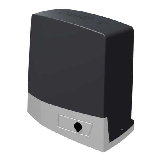
801MS-0350 BKV15AGE - Plus operator with 36 V motor, featuring a control board with graphic display, Adaptive Speed & Torque Technology, 4 safety inputs, magnetic limit switches and clock accessory included for gates weighing up to 1500 kg that are up to 20 m long. -
Page 6: Description Of Parts
Housing for SMA module Anchoring plate Magnetic limit switch* Housing for two emergency batteries Magnetic limit-switch tabs* Housing for thermostat with cartridge Clock card (806SA-0120)* Housing for the RGSM001 module Housing for the LBB card * Only for BKV15AGE, BKV20AGE and BKV25AGE... - Page 7 Connector for the RIOCN8WS module Connector for the clock card (806SA-0120) RSE card connector Terminal board for limit-switch micro-switches Connector for CAME KEY Accessories fuse Connector for plug-in radio frequency card (AF) Control board fuse Terminal board for connecting the antenna...
- Page 8 BKV20AGS BKV25AGS BKV15RGS BKV20RGS Pinion module Maximum gate-leaf length (m) Maximum gate-leaf weight (kg) 1500 2000 2500 1500 2000 MODELS BKV15AGE BKV20AGE BKV25AGE BKV15ALS BKV20ALS BKV25ALS Pinion module Maximum gate-leaf length (m) Maximum gate-leaf weight (kg) 1500 2000 2500 1500...
- Page 9 CONTINUOUS CONTINUOUS OPERATION OPERATION OPERATION OPERATION OPERATION Protection rating (IP) Insulation class Reduction ratio (i) Weight (kg) MODELS BKV15AGE BKV20AGE BKV25AGE BKV15ALS BKV20ALS BKV25ALS Power supply (V - 50/60 Hz) 230 AC 230 AC 230 AC 230 AC 230 AC...
- Page 10 Cable types and minimum thicknesses Cable length (m) up to 20 from 20 to 30 Power supply 230 V AC 3G x 1.5 mm2 3G x 2.5 mm2 24 V AC/DC flashing beacon 2 x 1 mm2 2 x 1 mm2 TX Photocells 2 x 0.5 mm2 2 x 0.5 mm2...
-
Page 11: Installation
INSTALLATION The following illustrations are examples only. The space available for fitting the operator and accessories varies depending on the area where it is installed. It is up to the installer to find the most suitable solution. The drawings show an operator fitted on the left. Preliminary operations Dig a hole for the foundation frame. - Page 12 Insert the screws supplied in the anchoring plate. Lock the screws in place with the nuts supplied. Remove the pre-shaped clamps using a screwdriver. Fit the anchoring plate in the iron cage. The tubes must pass through the existing holes. Position the anchoring plate, taking note of the measurements shown in the drawing.
- Page 13 Remove the nuts from the screws. Insert the electrical cables into the tubes until they protrude by about 600 mm. Setting up the operator Remove the operator cover. Place the operator on top of the anchoring plate. The electrical cables must pass under the operator foundation frame...
- Page 14 Male a hole in the cable gland. Thread the cables through the cable gland. Lift the operator by 5-10 mm from the plate by adjusting the threaded feet, to allow for any adjustments that may need to be made between the rack and pinion. Fastening the rack Release the operator.
- Page 15 Adjusting the pinion-rack coupling Open and close the gate manually. Adjust the pinion-rack coupling distance using the threaded feet (vertical adjustment) and the holes (horizontal adjustment). The weight of the gate must not bear down upon the operator. Fastening the operator in place Only fasten the operator after adjusting the pinion-rack coupling.
- Page 16 Determining the travel end points with mechanical limit switches Open the gate. Insert the opening limit-switch tab in the rack. The spring must trigger the microswitch. Fasten the opening limit-switch tab using the grub screws supplied. Close the gate. Insert the closing limit-switch tab in the rack. The spring must trigger the microswitch.
- Page 17 Establishing the limit-switch points with magnetic limit switches * Only for BKV15AGE, BKV20AGE and BKV25AGE Magnetic limit-switch tabs during closing Magnetic limit-switch tabs during opening Open the gate. Insert the magnetic opening limit-switch tab on the rack. The tab magnet must be between 10 and 30 mm from the magnetic sensor.
- Page 18 Close the gate. Insert the magnetic closing limit-switch tab on the rack. The tab magnet must be between 10 and 30 mm from the magnetic sensor. ~ 20 Fasten the support to the rack using the grub screws supplied. The limit-switch tab magnet must be perpendicular to the magnetic sensor. Fasten the limit-switch tab using the screw (supplied).
-
Page 19: Electrical Connections
ELECTRICAL CONNECTIONS Passing the electrical cables Connect all wires and cables in compliance with the law. The electrical cables must not touch any parts that may overheat during use (such as the motor and transformer). Use cable glands to connect the devices to the control panel. One of these must be used exclusively for the power supply cable. Power supply Make sure the mains power supply is disconnected during all installation procedures. -
Page 20: Signalling Devices
Remove the protective cover on the control board. Signalling devices Flashing beacon It flashes when the operator opens and closes. Additional light It increases the light in the manoeuvring area. Operator status warning light It notifies the user of the operator status. 10 11 E E3 5... -
Page 21: Command And Control Devices
Command and control devices Card reader Transponder selector switch Keypad selector STOP button (NC contact) Stop the gate and exclude automatic closing. Use a control device to resume movement. If the contact is not used, it must be deactivated during programming. Control device (NO contact) OPEN ONLY function Control device (NO contact) -
Page 22: Safety Devices
Safety devices Connect the safety devices to the CX, CY CZ and/or CK inputs (NC contacts). During programming, configure the type of action that must be performed by the device connected to the input. If contacts CX, CY, CZ and/or CK are not used, they must be deactivated during programming. DELTA photocells DELTA photocells Standard connection... - Page 23 Pair of sensitive edges DFWN Pair of sensitive edges DFWN Connected in parallel (recommended) Connected in series 10 TS 2 CX CY CZ CK 10 TS 2 CX CY CZ CK C NO NC C NO NC C NO NC C NO NC DFWN DFWN...
-
Page 24: Getting Started
PROGRAMMING Programming button functions ESC button The ESC button is used to perform the operations described below. Exit the menu Delete the changes Go back to the previous screen Stop the operator < > buttons The <> buttons are used to perform the operations described below. Navigate the menu Increase or decrease values <... - Page 25 Opening speed Set the opening speed (percentage of maximum speed). Configuration Opening speed 40% to 100% (Default 100%) Gate travel settings Closing speed Sets the closing speed (percentage of maximum speed). Configuration Closing speed 40% to 100% (Default 100%) Gate travel settings Opening slowdown speed Set the slowdown speed during opening (as a percentage of the maximum speed).
- Page 26 Opening slowdown point Set the opening slowdown start point, as a percentage of total travel. Configuration Opening slowdown point 10% to 60% (Default 25%) Gate travel settings Closing slowdown point Set the closing slowdown start point, as a percentage of total travel. Configuration Closing slowdown point 10% to 60% (Default 25%)
- Page 27 CZ input Associate a function with the CZ input. Configuration CZ input Deactivated (Default) Wired safety devices C1 = Reopen while closing (photocells) C2 = Reclose while opening (photocells) C3 = Partial stop C4 = Obstacle standby (photocells) C7 = Reopen while closing (sensitive edges) C8 = Reclose while opening (sensitive edges) C13 = Reopen while closing, with immediate stop once the obstruction has been removed, even if the gate is not in motion...
- Page 28 RIO ED T2 Associate one of the available functions to a wireless safety device. The function only appears if there is an interface board for wireless devices. Configuration RIO ED T2 Disabled (Default) RIO safety devices P0 = It stops the gate and excludes automatic closing. Use a control device to resume movement.
- Page 29 Removing obstacles If an obstacle is detected by the sensitive edge or by the amperometric sensor on the electronic board, movement is inverted to create a space sufficient to clear the obstacle. If this function is deactivated, the motion is inverted until the limit-switch is reached. Configuration Removing obstacles Deactivated (Default)
- Page 30 Configure the function to be performed by the card inserted in the RSE1 connector. If an RSE card – configured for paired connections – is plugged into the RSE_1 connector, use the RSE_2 connector for remote connection (CRP). In this case, a CAME KEY cannot be connected. Configuration...
- Page 31 New user Register up to a maximum of 250 users and assign a function to each one. The operation can be carried out by using a transmitter or another control device. The boards that manage the control devices (AF - R700 - R800) must be inserted into the connectors.
- Page 32 Change mode Change the function assigned to a specific user. Manage users Change mode Select the user for whom you want to change the command. You can select a user without using the arrows, by sending a command from the device associated with the user. Press ENTER to confirm.
- Page 33 Show clock Enable the clock on the display. Timer management Show clock Set the clock Set the date and time. Timer management Set the clock Use the arrows and the Enter button to enter the desired values. Automatic DST Enable automatic daylight saving time setting. Timer management Automatic DST Deactivated (Default)
- Page 34 Language Set the display language. Language Italiano (IT) English (EN) Français (FR) Deutsch (DE) Español (ES) Português (PT) Polski (PL) Русский (RU) Enable password Set a 4-digit password. The password will be requested to anyone who wants to access the main menu. Password Enable password Use the arrows and the Enter button to dial the desired code.
-
Page 35: Import/Export Data
Import/export data Save user data and system configuration data on a MEMORY ROLL card. The stored data can be reused for another control board to configure another system in the same way. Before inserting and removing the MEMORY ROLL card, DISCONNECT THE MAINS POWER SUPPLY TO THE LINE. Insert the MEMORY ROLL card into the corresponding connector on the control board. -
Page 36: Error Messages
Communication Configured on the wrong RSE port. error Incompatible remote The transmitter used is not CAME. control The coding set is different from that of the transmitter. The transmitters are TWIN and have different KEY BLOCK. Slave door open The SLAVE operator is released. -
Page 37: Final Operations
FINAL OPERATIONS... - Page 38 PAIRED OPERATION Two connected operators are controlled with one command. Electrical connections Connect the two electronic boards with a UTP CAT 5 cable. Fit an RSE card on both control boards, using the RSE_1 connector. Connect up the electrics for the devices and accessories. The devices and accessories must be connected to the control board which will be set as the MASTER.
- Page 39 MCBF Models BKV15 BKV20 BKV25 20 m - 1500 kg 250000 20 m - 2000 kg 250000 20 m - 2500 kg 250000 Installation in windy area -15% -15% -15% The percentages indicate how much the number of cycles should be reduced in relation to the type and number of accessories installed. Before carrying out any cleaning or maintenance, or replacing any parts, disconnect the device from the power supply.
- Page 40 CAME S.p.A. Via Martiri della Libertà, 15 31030 Dosson di Casier Treviso - Italy Tel. (+39) 0422 4940 Fax (+39) 0422 4941...
Need help?
Do you have a question about the BKV15AGE and is the answer not in the manual?
Questions and answers