Table of Contents
Advertisement
Quick Links
Advertisement
Table of Contents

Subscribe to Our Youtube Channel
Related Manuals for CAME BK-1200P


Summary of Contents for CAME BK-1200P
- Page 1 OPERATOR FOR SLIDING GATES FA 00605 - EN INSTALLATION MANUAL BK-1200P English...
- Page 2 ONLY USED PURPOSE MAINTENANCE OPERATION TO DO WITH THE POWER ON ONSTANTLY CLEAN THE WHICH IT WAS EXPLICITLY DESIGNED NY OTHER USE IS DANGEROUS CAME S. PHOTOCELLS GLASS COVERS USING A SLIGHTLY WATER MOISTENED CLOTH DO NOT LIABLE DAMAGE CAUSED •...
-
Page 3: Intended Use
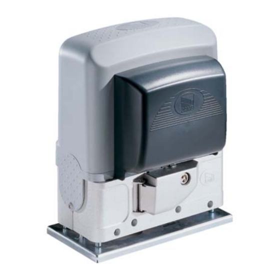
1,200 kg in weight and measuring 14 m in length. Intended use The BK-1200P is designed to power sliding gates in single homes and apartment blocks alike. Any installation and/or use other than that specifi ed in this manual is forbidden. - Page 4 Description of parts 1. Cover 7. Limit-switch fins 2. Gearmotor 8. Mechanical limit switch 3. Control board 9. Fan 4. Front cover 10. Transformer 5. Anchoring plate 11. Release hatch 6. Control-board holder 12. Release key Standard installation 1. Operator 7.
- Page 5 GENERAL INSTALLATION INDICATIONS ⚠ Only skilled, qualified staff must install this product. Preliminary checks ⚠ Before beginning the installation, do the following: • check that the gate is stable and that the casters are in good working order and lubricated; •...
- Page 6 Laying the anchoring plate Set up a foundation frame that is larger than the anchoring plate and sink it into the dug hole. The foundation frame must jut out by 50 mm above ground level. Fit an iron cage into the foundation frame to reinforce the concrete. Fit the bolts into the fastening plate and tighten them using the nuts.
- Page 7 Remove the nuts from the bolts. Fit the electric cables into the tubes so that they come out about 600 mm. Setting up the operator Remove both covers. Place the gearmotor above the anchoring plate. Careful! The electric cables must pass under the gearmotor case. Lift the gearmotor by about 5 to 10 mm from the plate, adjust the threaded rests to allow for future adjustments between the pinion and the rack.
- Page 8 Fastening the rack If the rack is already set up, the next step should be to adjust the rack-and-pinion coupling distance, otherwise, fasten it: - release the gearmotor (see RELEASING THE GEARMOTOR paragraph); - rest the rack above the gearmotor pinion; - weld or fasten the rack to the gate along its entire length.
-
Page 9: Establishing The Limit-Switch Points
Fastening the gearmotor Once adjusting is complete, fasten the gearmotor to the plate using the plates and nuts. Establishing the limit-switch points For opening: - open the gate ; - fi t the opening limit-switch tab onto the rack until the micro switch activates (spring) and fasten it using the grub screws . Spring ~ 20 mm For closing:... -
Page 10: Electrical Connections
ELECTRICAL CONNECTIONS ⚠ Warning! Before doing any work on the control board, cut off the mains power supply, and disconnect any batteries. Power supply to the control panel and control devices: 24 V AC/DC. Use DIP switches to set functions and the trimmer for adjustments. All connections are quick-fuse protected. -
Page 11: Power Supply
Connecting the gearmotor and the limit switches Description of the electrical connections is the same as that for installing on the left Motor 230V (AC) Orange Orange White Opening micro Closing micro switch switch Condenser Changes to the electrical connections for installing on the right White Invert the U-V gearmotor phases and the FA-FC limit-switch phases. -
Page 12: Command And Control Devices
Command and control devices STOP button (NC contact). For stopping the gate while excluding automatic closing. To resume movement either press the control button or any other control device. If unused, set DIP switch to ON. ONLY OPEN function from control device (NO contact) PARTIAL OPENING feature from command device (NO contact). -
Page 13: Safety Devices
Safety devices Configure contact C1 and/or C5 (NC), input for safety devices such Dir/DeltaS as photocells, which comply with EN 12978 regulations. C1 partial stop. Gate stops, if it is moving, and prepares to automatically close (if this function is activated). C3 reopening during closing. - Page 14 Features selection L1T L2T CT EB EB ELECTRIC ACCESSORIES BLOCK LINE 1.6A FUSE BOARD 315mA BATTERY 1.6A CONTROL BOARD ZBK8 9 10 + A. C.T. - + PAR.OP - DIP-SWITCH Description of functions 1 ON AUTOMATIC CLOSING (1 OFF - deactivated) 2 ON OPEN-STOP-CLOSE-STOP from button on 2-7 and/or from transmitter (with AD card fitted) 2 OFF...
-
Page 15: Electric Lock
PRATICO SYSTEM Disconnect the 230 V power supply and fi t the AF radio card into slot AF2 ①, the mother board recognizes it only when it is battery powered. Fit the (-/+) ② terminal connected to the battery into the motherboard connector. - Page 16 ACTIVATING THE RADIO CONTROL A Connect the RG58 cable to the antenna. Cut off themains power supply, disconnect the batteries. B Fit the AF card into the control board. The control board recognizes the AF card only when it is the mains power supply is restored. C Keep pressed the CH1 key on the control board: the alert LED will flash.
-
Page 17: Final Operations
• Make the same adjustments and activate the same functions on both boards. 9 10 + A. C.T. - + A. C.T. + PAR.OP - + PAR.OP • Connect the two control boards, as shown in the fi gure. • Set DIP switches 1 and 3 to ON; on both boards. For opening with the radio command, connect an external receiver ((RExxx/RBExxx with relay switch in MONOSTABLE mode) to terminals 2-3 of gearmotor FINAL OPERATIONS... -
Page 18: Troubleshooting
RELEASING THE GEARMOTOR ⚠ This procedure must be done with the main power cut off . ⚠ Manually releasing the operator may result in uncontrolled movement of the gate, if this has any mechanical problems or is unbalanced. ⚠ When the release hatch door is open, the operator cannot work. RELEASING LOCKING TROUBLESHOOTING... -
Page 19: Maintenance
MAINTENANCE Periodic maintenance ☞ Before doing any maintenance, cut off the power supply, to prevent any hazardous situations caused by accidentally activating the operator. Periodic maintenance log kept by users (every six months) Date Notes Signature Extraordinary maintenance ⚠ The following table is for logging any extraordinary maintenance jobs, repairs and improvements performed by specialized contractors. ... -
Page 20: Dismantling And Disposal
DISMANTLING AND DISPOSAL ☞ CAME S.p.A. applies a certified Environmental Management System at its premises, which is compliant with the UNI EN ISO 14001 standard to ensure the environment is safeguarded. Please continue safeguarding the environment. At CAME we consider it one of the fundamentals of our operating and market strategies. Simply...
Need help?
Do you have a question about the BK-1200P and is the answer not in the manual?
Questions and answers