Table of Contents
Advertisement
Quick Links
Advertisement
Table of Contents

Subscribe to Our Youtube Channel
Related Manuals for PR 4222


Summary of Contents for PR 4222
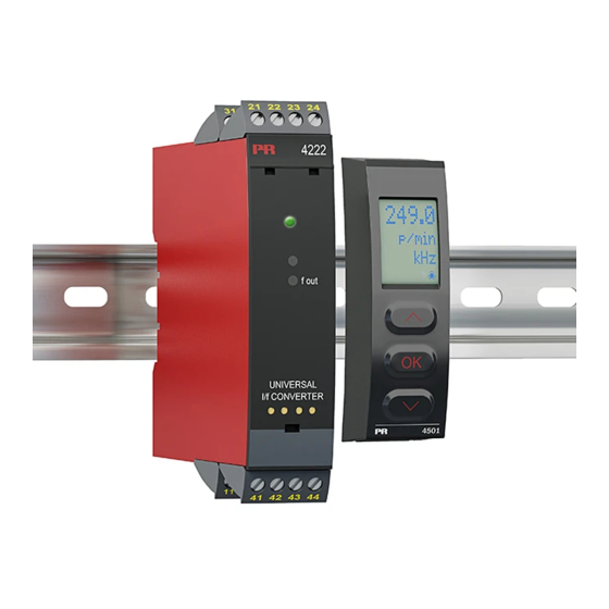
- Page 1 PERFORMANCE MADE SMARTER Product manual 4222 Universal I/f converter T E M P E R AT U R E I . S . I N T E R FA C E S CO M M U N I C AT I O N I N T E R FA C E S...
- Page 2 All the interfaces are detachable, have a built-in display for readout of process values and diagnostics, and can be configured via push-buttons. Product specific functionality includes communication via Modbus and Bluetooth and remote access using our PR Process Supervisor (PPS) application, available for iOS and Android. Communication Our unique range of single devices covering multiple applications is easily deployable as your site standard.
-
Page 3: Table Of Contents
Electrical specifications ................. . Visualisation in the PR 4500 of sensor error detection and input signal outside range...... -
Page 4: Warning
HAZARD- Troubleshooting the device. VOLTAGE Repair of the device and replacement of circuit breakers must be done by PR electronics A/S only. CAUTION Warning Do not open the front plate of the device as this will cause damage to the connector for the display / programming front PR 4500. -
Page 5: Safety Instructions
When disconnected, the device may be cleaned with a cloth moistened with distilled water. Liability To the extent the instructions in this manual are not strictly observed, the custom er cannot advance a demand against PR electronics A/S that would otherwise exist according to the concluded sales agreement. -
Page 6: How To Demount System 4000
How to demount system 4000 First, remember to demount the connectors with hazardous voltages. Picture 1: The device is detached from the DIN rail by moving the bottom lock down. 4222V101-UK... -
Page 7: Application
When 4222 is used in combination with the PR 4500 display / programming units, all operational parameters can be modified to suit any application. As the 4222 is designed with electronic hardware switches, it is not necessary to open the device for setting of DIP-switches. -
Page 8: Applications
Applications Input signals: Volt - Potentio- meter Current RTD and lin.R Connect., wires Output signals: Frequency output PNP, +24 V NPN, 24 V Out., Gnd TTL, 5 V Supply: 21.6...253 VAC 19.2...300 VDC 4222V101-UK... -
Page 9: Pr 4500 Display / Programming Front
Demounting of the PR 4500 3: Push the release button on the bottom of the PR 4500 and hinge the the PR 4500 out and up. 4: With the PR 4500 hinged up, remove from holes at the top of the device. -
Page 10: Order
Programming ........ - Page 11 Accuracy, the greater of general and basic values: General values Input type Absolute accuracy Temperature coefficient ≤ ±0.1% of span ≤ ±0.01% of span / °C Basic values Type Basic accuracy Temperature coefficient ≤ ±4 µA ≤ ±0.4 µA / °C ≤...
- Page 12 TC input Min. Max. Type Standard value value +400°C +1820°C IEC 60584-1 -100°C +1000°C IEC 60584-1 -100°C +1200°C IEC 60584-1 -180°C +1372°C IEC 60584-1 DIN 43710 -200°C +900°C -180°C +1300°C IEC 60584-1 -50°C +1760°C IEC 60584-1 -50°C +1760°C IEC 60584-1 -200°C +400°C IEC 60584-1...
- Page 13 TTL output max........15 mA sink/source peak .
-
Page 14: Visualisation In The Pr 4500 Of Sensor Error Detection And Input Signal Outside Range
Visualisation in the PR 4500 of sensor error detection and input signal outside range Sensor error check: Device Configuration Sensor error detection: OUT.ERR=NO 4222 Else: Signal conditioning limits Outside range readout (IN.LO, IN.HI): If the valid range of the A/D converter or the polynomial is exceeded... -
Page 15: Error Indications
Check that input signal matches input IN.ER 1) Error levels on input configuration Check that saved configuration in PR 4500 mat- TY.ER Configuration is not 4222 ches device All error indications in the display flash once per second. The help text explains the error. If the error is a sensor error, the display backlight flashes as well - this is acknowledged (stopped) by pushing the 3 button. -
Page 16: Connections
Connections Supply Inputs: RTD, 2-wire RTD, 3- / 4-wire Resistance, 2-wire 41 42 41 42 41 42 Resistance, 3- / 4-wire Potentiometer 2-wire transmitter Current 41 42 41 42 41 42 41 42 Voltage 41 42 Outputs: 21 22 21 22 21 22 + 5 V + 24 V... -
Page 17: Block Diagram
Block diagram RTD and lin. R, Supply connection 21.6...253 VAC or wires 0.2 mA 19.2...300 VDC loop Supply Frequency generator PNP, 24 V Green 20 Ω EEPROM Yellow 50.0 l / min VALVE 5 Gnd. 4222 TTL, 5 V 4222V101-UK... -
Page 18: Configuration / Operating The Function Keys
(not necessarily 0%) is applied and the actual value is entered via PR 4500. Then a high signal (not necessarily 100%) is applied and the actual value is entered via PR 4500. If you accept to use the calibration, the device will work according to this new adjustment. - Page 19 Auto diagnosis The device performs an advanced auto diagnosis of the internal circuits. The following possible errors can by displayed in the front unit PR 4500. CJ.ER - CJC sensor defect or CJC temperature outside range FL.ER - Flash error NO.CO - Connection error...
-
Page 20: Routing Diagram
Routing diagram Power up If no key is activated for 1 minute, the display will return to the default state 1.0 without saving configuration changes. 1 Increase value / choose next parameter 2 Decrease value / choose previous parameter 3 Save the chosen value and proceed to the next menu Hold 3 Back to previous menu / return to menu 1.0 without saving. - Page 21 p / m p / h 999.9 50%DC p / d -199.9 25000 25000 25000 prg p 1000 100.0 25.00 DISP.HI OU.UN f.min f.max CUT.OFF O.TYPE t.PULSE Txt 14 Txt 20 Txt 21 Txt 22 Txt 23 Txt 19 Txt 24 f>500 Hz 50% DC 50%DC...
- Page 22 4172 4172 26250 -328 -328 To default OUT.ERR f.ERR RESP OUT.LO OUT.HI state 1.0 Txt 25 Txt 26 Txt 40 Txt 41 Txt 42 315000 OUT.ERR f.ERR Txt 25 Txt 26 1.2 = Not valid for these input signals: 0...20 mA and voltage.
-
Page 23: Routing Diagram, Advanced Settings (Adv.set)
Routing diagram, advanced settings (ADV.SET) DISP PASS 2.0 In the submenu simulation (SIM) you must press 3 SAVE LANG to return to the default state 1.0. LOAD LATC SAVE SETUP MEMORY Txt 43 Txt 44 f.OUT DISP f.OUT SETUP CONTRA LIGHT VALVE 5 LINE 3... -
Page 24: Help Text Overview
Help text overview [01] Set correct password Select TC-W5 as sensor type [02] Enter advanced setup menu? Select TC-Lr as sensor type [19] [03] Select temperature input Select 50% duty cycle output Select programmable pulse time Select potentiometer input [20] Select Hz as output unit Select linear resistance input Select pulses/minute as output unit... -
Page 25: Document History
Document history The following list provides notes concerning revisions of this document. Rev. ID Date Notes 0845 Initial release of the product. 1311 FM and EAC approvals added. 4222V101-UK... - Page 26 We are near you, all over the world Our trusted red boxes are supported wherever you are All our devices are backed by expert service and a 5-year business with a global reach. This means that we are warranty. With each product you purchase, you receive always nearby and know your local markets well.
- Page 27 Benefit today from PERFORMANCE MADE SMARTER PR electronics is the leading technology company specialized in making industrial process control safer, more reliable and more efficient. Since 1974, we have been dedicated to perfecting our core competence of innovating high precision technology with low power consumption.
Need help?
Do you have a question about the 4222 and is the answer not in the manual?
Questions and answers