
Related Manuals for PR 9113 Series


Summary of Contents for PR 9113 Series
- Page 1 9 1 1 3 T e m p e r a t u r / m A W a n d l e r N o . 9 1 1 3 V 1 0 4 - D E P r o d u k t v e r s i o n : 9 1 1 3 - 0 0 4 S I G N A L S T H E B E S T...
- Page 2 PR electronics A/S tilbyder et bredt program af analoge og digitale signalbehandlingsmoduler til industriel automation. Programmet består af Isolatorer, Displays, Ex-barrierer, Temperaturtransmittere, Universaltransmittere mfl. Vi har modulerne, du kan stole på i selv barske miljøer med elektrisk støj, vibrationer og temperaturud- sving, og alle produkter opfylder de strengeste internationale stan- darder.
-
Page 3: Table Of Contents
Zerlegung des Systems 9000 ..........EG-Konformitätserklärung ..........Erweiterte Merkmale ............Verwendung ................ Technische Merkmale ............Anwendungen ..............PR 4501 Display / Programmierfront ......... Bestellangaben 9113 ............Zubehör ................Elektrische Daten ............... Konfiguration der Sensorfehlerüberprüfung ....... 14 Eingangssignal außerhalb des Bereichs ......14 Fühlerfehlererkennung ............. -
Page 4: Warnung
Installation, Montage und Demontage von Leitungen. Fehlersuche im Gerät. reparaturen des gerätes und Austausch von sicherungen dürfen nur von pr electronics A/s vorgenommen werden. WArnung Die Frontplatte des Gerätes darf nicht geöffnet werden, weil hier durch die Kontakte zur Kontaktierung des Frontdisplays 4501 beschädigt werden können. - Page 5 Sollten Zweifel bezüglich der richtigen Handhabung des Gerätes bestehen, sollte man mit dem Händler vor Ort Kontakt aufnehmen. Sie können aber auch direkt mit pr electronics gmbh, www.prelectronics.dk Kontakt aufnehmen. Der Einsatz von verdrillter Leitung ist nicht erlaubt außer die Enden sind mit Aderendhülsen versehen.
-
Page 6: Zerlegung Des Systems 9000
Wasser leicht angefeuchtet ist. hAfTung In dem Umfang, in welchem die Anweisungen dieses Handbuches nicht genau eingehalten werden, kann der Kunde PR electronics gegenüber keine Ansprüche geltend machen, welche ansonsten entsprechend der eingegange- nen Verkaufsvereinbarungen existieren können. -
Page 7: Eg-Konformitätserklärung
Als Hersteller bescheinigt pr electronics A/s lerbakken 10 dk-8410 rønde hiermit für das folgende Produkt: Typ: 9113 name: Temperatur / mA Wandler die Konformität mit folgenden Richtlinien und Normen: Die EMV Richtlinien 2004/108/EG und nachfolgende Änderungen en 61326-1 : 2006 Zur Spezifikation des zulässigen Erfüllungsgrades, siehe die Elektrische... -
Page 8: Erweiterte Merkmale
• 1 oder 2 Kanäle • Kann separat über Klemmenanschluss oder über die Power Rail 9400 versorgt werden • SIL 2-zertifiziert über Full Assessment erweiterte merkmale • Konfiguration und Überwachung über das abnehmbare Frontdisplay (PR 4501); Prozesskalibrierung und Signalsimulierung. • Kopieren der Konfiguration zwischen Geräten des gleichen Typs über das abnehmbare Frontdisplay 4501. • Temperaturkompensation entweder über die interne CJC oder zur höheren Genauigkeit die externe CJC mittels einer Anschlussklemme mit integrierten Pt100 (5910Ex, Kanal 1 / 5913Ex, Kanal 2) benutzen. -
Page 9: Anwendungen
AnWendungen Eingangssignale: Ausgangssignale: Analog, 0/4...20 mA Kanal 1: Strom Kanal 2: Verbindung, 2-Draht-Versorgung - Leiter Kanal 1: 2-Draht-Versorgung - Power Rail Bitte die CJC-Anschlus- sklemme Typ 5910Ex/ 5913Ex separat bestellen! Fehler-Signal Rail, +24 VDC Rail, Erde Keine Verbindung Keine Verbindung Kanal 2: Versorgungsanschluss: Strom... -
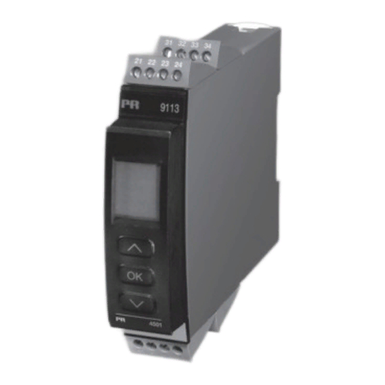
Page 10: Pr 4501 Display / Programmierfront
4501 dIsplAy / progrAmmIerfronT funktionallität Die einfache Menüstruktur leitet automatisch durch die relevanten Einstellungen. Der scrollende Hilfetext macht es sehr einfach diese Geräte einzusetzen. Sie finden weitere Beschreibungen der Funktionen und Programmierungsmög- lichkeiten im Abschnitt ”Konfiguration / Bedienung der Funktionstasten”. -
Page 11: Bestellangaben 9113
Bestellangaben 9113 kanäle 9113 Einfach Zweifach zubehör 4501 = display- / programmierfront 5910ex = cJc-Anschlussstecker, kanal 1 5913ex = cJc-Anschlussstecker, kanal 2 9400 = power rail 9404 = Arretierblock für rail 9410 = power control unit 9420 = spannungsversorgung 24 v / 120 W - ex nAc elektrische daten Umgebungstempeatur ........ - Page 12 grundwerte Eingangs- Grund- Temperatur- genauigkeit koeffizient ≤ ±16 µA ≤ ±1,6 µA / °C Pt100, Pt200, ≤ ±0,2°C ≤ ±0,02°C / °C Pt 1000 Pt500, Ni100, ≤ ±0,3°C ≤ ±0,03°C / °C Ni120, Ni 1000 ≤ ±0,4°C ≤ ±0,04°C / °C Pt50, Pt400, Ni50 ≤...
- Page 13 WTh-eingang: Eingangs- Min. Max. Wert Wert Norm Pt100 -200°C +850°C IEC 60751 Ni100 -60°C +250°C DIN 43760 Eingang für TE-Typen: Pt10*, Pt20*, Pt50*, Pt100, Pt200, Pt250, Pt300, Pt400, Pt500, Pt1000 Ni50, Ni100, Ni120, Ni1000 Kabelwiderstand pro Leiter (max.) ....50 Ω Fühlerstrom ..........
- Page 14 Fühlerfehlererkennung ......... Programmierbar ON oder OFF (nur Kabel Drahtbruch) Fühlerfehlerstrom: bei Erkennung ........Nom. 2 μA sonst ............ 0 μA stromeingang: Messbereich ..........0...20 mA Programmierbare Messbereiche ....0...20 und 4...20 mA Eingangswiderstand ........Nom. 20 Ω + PTC 50 Ω Fühlerfehlererkennung .........
- Page 15 zulassungen: EMV 2004/108/EG ........EN 61326-1 LVD 2006/95/EG .......... EN 61010-1 c UL us, Standard for Safety ...... UL 61010-1 GOST R marine: Det Norske Veritas, Ships & Offshore ..Stand. f. Certific. No. 2.4 I.s. / ex: ATEX 94/9/EG ..........KEMA 07ATEX0148 X IECEx ............
-
Page 16: Konfiguration Der Sensorfehlerüberprüfung
konfiguration der sensorfehlerüberprüfung Sensorfehlerüberprüfung: Gerät: Konfiguration Fühlerfehlererkennung OUT.ERR=NONE. 9113 Sonst: visualisierung im 4501: eingangssignal außerhalb des Bereichs Außerhalb des Bereichs Anzeige (IN.LO, IN.HI): Bei Verlassen des Gewählten Bereichs des A/D-Wandlers oder des Polynoms Eingang Bereich Anzeige Grenze IN.LO < -1,05 mA CURR 0...20 mA / 4...20 mA IN.HI... - Page 17 Anzeige bei Hardware Fehler Fehlersuche Anzeige Grund Eingangssignalwerte außerhalb des Eingangs-Fehler - Verbindungen kontrollieren und IN.ER Bereichs oder an falsche Klemmen Versorgung kurz unterbrechen angeschlossen* Fehler im analogen Ausg. - Verbindungen Fehler im analogen Stromausgang AO.ER kontrollieren und Versorgung kurz unterbrechen (nur SIL-Modus)* Keine Kommunikation zwischen Keine Kommunikation...
-
Page 18: Anschlüsse
Anschlüsse Versorgung und Power Rail Statusrelais Verbindungen 31 32 33 34 91 92 93 94 95 N.C. Erde Erde +24 V +24 V Fehler-Signal eingänge NC = keine Verbindung TE, interner *TE, WTH, 2-Leiter WTH, 3- / 4-Leiter Temperatur-Fühler CJC-Stecker 41 42 43 44 41 42 43 44 41 42 43 44... -
Page 19: Blockdiagramm
BlockdIAgrAmm 9113 - Product Version 9113-004... -
Page 20: Signalfehler- Und Kabelfehler Erkennung Ohne Frontdisplay
signalfehler- und kabelfehler erkennung ohne frontdisplay 9113 - Product Version 9113-004... -
Page 21: Konfiguration / Bedienung Der Funktionstasten
konfIgurATIon / BedIenung der funkTIonsTAsTen Dokumentation für das Flussdiagramm. grundsätzliches Bei der Konfiguration des 9113 werden Sie durch alle Parameter geleitet und Sie können die Einstellungen wählen, welche zur Applikation passt. Für jedes Menü existiert ein scrollender Hilfetext welcher automatisch in der 3. Zeile im Display gezeigt wird. - Page 22 Im CJC-Menü haben Sie die Wahl zwischen externer und interner Kaltstellenkompensation (CJC). Die externe CJC-Anschlussklemme PR 5910Ex/5913Ex muss separat bestellt werden. signal- und sensorfehlerinformation per programmierfront 4501 Sensorfehler (s. Grenzen im Diagramm), wird als SE.BR (Sensorfehler) oder SE.SH (Fühlerkurzschluß) angezeigt. Signale, ausserhalb des gewählten Bereichs (kein Sensorfehler, s.
- Page 23 UK, DE, FR, IT, ES, SE und DK. Power Rail: Im Menü ”Rail” können Sie wählen, ob Sensor-Fehler an die zentrale Überwachung im Power Control Unit PR 9410 weitergegeben werden sollen. safety Integrity level (sIl): Für Details sehen Sie bitte im Sicherheitshandbuch (Safety Manual) nach.
- Page 24 flussdIAgrAmm Wenn für eine Dauer von 1 Minute keine Taste betätigt wird, kehrt das Display auf den Menüpunkt 1.0 zurück und eventuelle Änderungen in der Power up Konfiguration werden nicht gespeichert. 1 Wert erhöhen / nächsten Parameter wählen 2 Wert herabsetzen / vorheringen Parameter Wählen 3 Parameter speicher und nächsten Parameter wählen ...
- Page 25 999.9 999.9 -199.9 -199.9 Konfiguration von 150.0 Kanal 2 identisch zum OUT.LO OUT.HI RESP. Zum Normal-Zustand 1.0 Txt 14 Txt 15 Txt 35 Kanal 1 9113 - Product Version 9113-004...
-
Page 26: Flussdiagram, Erweiterte Einstellungen (Adv.set)
MEM, DISP, flussdIAgrAm, CAL, SIM, SAVE PASS, LANG, LOAD RAIL, SIL ERWEITERTE EINSTELLUNGEN (ADV.SET) SAVE SETUP MEMORY Txt 17 Txt 18 A.OUT A.IN DISP TAG1 TAG2 A.OUT SETUP CONTRA LIGHT VALVE 5 TEMP 4 DISP Txt 17 Txt 19 Txt 20 Txt 21 Txt 21... -
Page 27: Scrollender Hilfstext Im Display Zeile 3
scrollender hIlfsTeXT Im dIsplAy zeIle 3 Einstellung Temperatur für Analogausgang LOW [01] Einstellung des korrekten Passwortes [14] Einstellung Temperatur für Analogausgang HIGH [02] Eingabe erweitertes Setup Menü? [15] Aktivierung Power Rail Statussignal? [03] Auswahl Temperatur-Eingang [16] Eingabe SIL Einstellungen Auswahl Stromeingang [17] Eingabe Simulationsmodus [04]... -
Page 28: Appendix
AppendIX Iecex Installation drawing ATeX Installation drawing fm Installation drawing safety manual 9113 - Product Version 9113-004... -
Page 29: Iecex Installation Drawing
9113QI01 LERBAKKEN 10, 8410 RØNDE DENMARK IECEx Installation drawing 9113 For safe installation of 9113B the following must be observed. The module shall only be installed by qualified personnel who are familiar with the national and international laws, directives and standards that apply to this area. Year of manufacture can be taken from the first two digits in the serial number. - Page 30 9113QI01 LERBAKKEN 10, 8410 RØNDE DENMARK Ex input CH1 (terminal 41,42,43,44) CH2 (terminal 51,52,53,54) 8.7 V 18.4 mA 40 mW Lo/Ro 892 μH/Ω IIA or I 5 µF 50 µF 1000 µF 100 mH 300 mH 700 mH 10 V 30 mA 30 nF 820 nH...
- Page 31 9113QI01 LERBAKKEN 10, 8410 RØNDE DENMARK Hazardous area Non Hazardous area Zone 0,1,2, 20, 21, 22 or Zone 2 -20 ≤Ta ≤ +60ºC 4501 9113 91 92 93 94 95 Power Rail Ex input CH1 (terminal 43 +) (terminal 11,12,13,14) CH2 (terminal 52 - ) (terminal 31,32,33,34) (terminal...
-
Page 32: Atex Installation Drawing
4501 Für die Installation in Zone 2 ist Folgendes zu beachten: Das aufsteckbare Frontdisplay 4501 zur Programmierung ist ausschließlich mit PR electronics- Geräten zu verwenden. Es ist wichtig, dass das Display unbeschädigt ist, nicht umgebaut oder in irgendeiner Weise verändert wurde. Das 4501 darf nur frei von Staub und Feuchtigkeit installiert werden. - Page 33 9113QA01 LERBAKKEN 10, 8410 RØNDE DENMARK Ex-Eingang Kanal 1 (Klemmen 41,42,43,44) Kanal 2 (Klemmen 51,52,53,54) 8,7 V 18,4 mA 40 mW Lo/Ro 892 μH/Ω IIA or I 5 µF 50 µF 1000 µF 100 mH 300 mH 700 mH 10 V 30 mA 30 nF 820 nH...
- Page 34 9113QA01 LERBAKKEN 10, 8410 RØNDE DENMARK Ex-Bereich Nicht Ex-Bereich Zone 0,1,2, 20, 21, 22 oder Zone 2 -20 ≤Ta ≤ +60ºC 4501 9113 91 92 93 94 95 Power Rail Ex-Eingang Kanal 1 (Klemme 43) (Klemmen 11,12,13,14) Kanal 2 (Klemme 52) (Klemmen 31,32,33,34) (Klemmen 91,92,93,94,95) 17,4 V...
-
Page 35: Fm Installation Drawing
9113QF01 LERBAKKEN 10, 8410 RØNDE DENMARK FM Installation drawing 9113 For safe installation of 9113B the following must be observed. The module shall only be installed by qualified personnel who are familiar with the national and international laws, directives and standards that apply to this area. Year of manufacture can be taken from the first two digits in the serial number. - Page 36 9113QF01 LERBAKKEN 10, 8410 RØNDE DENMARK Ex input CH1 (terminal 41,42,43,44) CH2 (terminal 51,52,53,54) Vt (U 8.7 V It (I 18.4 mA 40 mW Lo/Ro 892 μH/Ω IIC / IIB / IIA / Group A,B Group C,E,F Group D,G 5 µF 50 µF 1000 µF 100 mH...
- Page 37 9113QF01 LERBAKKEN 10, 8410 RØNDE DENMARK Hazardous Classified Location Unclassified Location or Hazardous Classified Location Class I/II/III, Division 1, Group A,B,C,D,E,F,G or Class I, Zone 0/1 Group IIC, [AEx ia] IIC Class I, Division 2, Group A,B,C,D T4 or Class I, Zone 0/1 Group IIC, [Ex ia] IIC or Class I, Zone 2 Group IIC T4 -20 ≤...
-
Page 38: Safety Manual
Safety manual temperature / ma COnVerter 9113 this safety manual is valid for the following product versions: 9113-004 9113-003 9113-002 Version No. V6R0... - Page 39 9113 TemperaTure / ma CONVerTer Safety manual 0 COntentS 1 Observed standards ..................... 2 Acronyms and abbreviations ..................3 Purpose of the product ....................4 Assumptions and restrictions for use of the product ..........4.1 Basic safety specifications .................. 4.2 Safety accuracy ....................4.2.1 Minimum span ..................
- Page 40 Safety Manual 9113 TeMperaTure / ma CONVerTer 15 Fault reaction and restart condition ................16 User interface ....................... 16.1 Scrolling help texts in display line 3 ................. 16.2 Routing diagram ....................16.3 Routing diagram - Advanced settings (ADV.SET)..........17 Connections diagram ....................Version No.
-
Page 41: Observed Standards
9113 TemperaTure / ma CONVerTer Safety manual Observed standards Standard Description Functional Safety of electrical / electronic / programmable electronic IEC 61508 safety-related systems IEC 61508- Part 2: Requirements for electrical / electronic / programmable electronic 2:2000 safety-related systems IEC 61508- Part 3: Software requirements 3:1998 IEC 61326-3-... -
Page 42: Assumptions And Restrictions For Use Of The Product
Safety Manual 9113 TeMperaTure / ma CONVerTer assumptions and restrictions for use of the product Basic safety specifications Operational temperature range....-20...+60°C Storage temperature range...... -20...+85°C Power supply type, min......Double or reinforced Supply voltage ......... 19.2...31.2 VDC External loop supply voltage ....5...26 VDC + external drop Mounting area .......... -
Page 43: Sensor Errors
9113 TemperaTure / ma CONVerTer Safety manual 4.3.2 Sensor errors If Sensor error detection is disabled, if current input range 0...20 mA is selected or if input type Pt10, Pt20, or Pt50 is selected, the end user must ensure that the applied sensor including wiring has a failure rate qualifying it for the safety application without sensor error detection enabled. -
Page 44: Safety Parameters
Safety Manual 9113 TeMperaTure / ma CONVerTer Safety parameters Probability of dangerous Failure per Hour (PFH) 6.10E-08 Note Probability of failure on demand (PFD) - 3.96E-04 1 year proof test interval Proof test interval (10% of loop PFD) 3 years Safe Failure Fraction 90.7 % Demand response time... -
Page 45: Periodic Proof Test Procedure
Any failures that are detected and that compromise functional safety should be reported to the sales department at PR electronics A/S. Repair of the device and replacement of circuit breakers must be done by PR electronics A/S only. 12 maintenance No maintenance required. -
Page 46: Further Explanations
Safety Manual 9113 TeMperaTure / ma CONVerTer 13.2 further explanations 13.2.1 password protection Access to the configuration can be blocked by assigning a password. The password is saved in the device in order to ensure a high degree of protection against unauthorised modifications to the configuration. Default password 2008 allows access to all configuration menus. -
Page 47: Process Calibration (Cal)
13.3.6 power rail (raIl) In this menu it can be chosen if errors in the device are transmitted to the central surveillance in the PR 9410 power control device. 13.3.7 Simulation (SIm) It is possible to override the actual measured input signal by a simulated value. -
Page 48: Safe Parameterisation - User Responsibility
Safety Manual 9113 TeMperaTure / ma CONVerTer 14 Safe parameterisation - user responsibility 14.1 Safety-related configuration parameters 14.1.1 parameters related only to Channel 1 Name Function CH1.TYP Selected input type: TEMP = Temperature CURR = Current I.RANGE Selected fixed input range for current measurements (for CH1. TYP = CURR): 0_20 = 0...20 mA (no sensor error detection!) 4_20 = 4...20 mA... - Page 49 9113 TemperaTure / ma CONVerTer Safety manual Name Function Ni.TYPE Ni sensor type (for SENSOR = Ni): 50 = Ni50 100 = Ni100 120 = Ni120 1000 = Ni1000 TC.TYPE Thermocouple type (for SENSOR = TC): TC.B = Thermocuple type B TC.E = Thermocuple type E TC.J = Thermocuple type J TC.K = Thermocuple type K...
- Page 50 Safety Manual 9113 TeMperaTure / ma CONVerTer Name Function OUT.ERR Fixed output value on detected sensor error: NONE = Sensor error detection NOT enabled, output at sensor error is undefined. The end user must ensure that the applied sensor including wiring has a failure rate qualifying it for the safety application without the detection enabled.
-
Page 51: Parameters Related Only To Channel 2 (Only For Type 9113Bb)
SIL configuration. 14.2. Verification procedure The verification is done using the display / programming front PR 4501 and following the procedure described below. Version No. V6R0... -
Page 52: If No Password Is Set
Safety Manual 9113 TeMperaTure / ma CONVerTer 14.2.1 If no password is set action Display shows Press OK ADV.SET Set (ADV.SET) to Yes and press OK SETUP Set SETUP to SIL and press OK EN.SIL Set EN.SIL to YES and press OK NEW.PAS Set password to a number between 0 and CONFIG... - Page 53 9113 TemperaTure / ma CONVerTer Safety manual Action Display shows Verify CJC type and press OK O.RANGE (ONLY IF SENSOR = TC and CH1.TYP = TEMP) Verify fixed output range and press OK OUT.ERR Verify fixed output value on detected sensor error OUT.LO and press OK (ONLY IF CH1.TYP = TEMP, or IF I.RANGE = 4-20...
- Page 54 Safety Manual 9113 TeMperaTure / ma CONVerTer Action Display shows Verify Ni sensor type and press OK TC.TYPE (ONLY IF SENSOR = Ni and CH2.TYP = TEMP) Verify Thermocouple type and press OK (ONLY IF SENSOR = TC and CH2.TYP = TEMP) Verify CJC type and press OK O.RANGE (ONLY IF SENSOR = TC and CH2.TYP = TEMP)
-
Page 55: If Password Is Set
9113 TemperaTure / ma CONVerTer Safety manual 14.2.2 If password is set action Display shows Press OK PASSW Enter password and press OK ADV.SET Set ADV.SET to Yes and press OK SETUP Set SETUP to SIL and press OK EN.SIL Set EN.SIL to YES and press OK CONFIG (At this time the device starts operating... -
Page 56: User Interface
Safety Manual 9113 TeMperaTure / ma CONVerTer 16 user interface 16.1 Scrolling help texts in display line 3 Enter SIL setup [01] Set correct password [17] Enter simulation mode [02] Enter advanced setup menu? Enter RAIL setup [03] Select temperature input Perform process calibration Select current input Enter language setup... -
Page 57: Routing Diagram
9113 TemperaTure / ma CONVerTer Safety manual 16.2 routing diagram If no key is activated for 1 minute, the display will return to the default state 1.0 Power up without saving configuration changes. 1 Increase value / choose next parameter 2 Decrease value / choose previous parameter 3 Accept the chosen value and proceed to the next menu ... - Page 58 Safety Manual 9113 TeMperaTure / ma CONVerTer 999.9 999.9 -199.9 -199.9 150.0 Configuration of OUT.LO OUT.HI RESP. To default state 1.0 identical to CH1 Txt 14 Txt 15 Txt 15 Version No. V6R0...
-
Page 59: Routing Diagram - Advanced Settings (Adv.set)
9113 TemperaTure / ma CONVerTer Safety manual MEM, DISP, 16.3 routing diagram - CAL, SIM, SAVE PASS, LANG, advanced settings (aDV.Set) LOAD RAIL, SIL SAVE SETUP MEMORY Txt 17 Txt 18 A.OUT A.IN DISP TAG1 TAG2 A.OUT SETUP CONTRA LIGHT VALVE 5 TEMP 4 DISP... -
Page 60: Connections Diagram
Safety Manual 9113 TeMperaTure / ma CONVerTer 17 Connections diagram Supply and Power Rail status relay connections 31 32 33 34 31 32 33 34 91 92 93 94 95 91 92 93 94 95 N.C. Gnd. Gnd. +24 V +24 V Error signal Inputs... - Page 61 displays Programmable displays with a wide selection of inputs and outputs for display of temperature, volume and weight, etc. Feature linearisation, scaling, and difference measurement functions for programming via PReset software. ex interfaces Interfaces for analogue and digital signals as well as HART signals between sensors / I/P converters ®...
- Page 62 www.prelectronics.se sales@prelectronics.se www.prelectronics.co.uk sales@prelectronics.co.uk www.prelectronics.com sales@prelectronics.com www.prelectronics.cn sales@prelectronics.cn Head office Denmark www.prelectronics.com PR electronics A/S sales@prelectronics.dk Lerbakken 10 tel. +45 86 37 26 77 DK-8410 Rønde fax +45 86 37 30 85...
Need help?
Do you have a question about the 9113 Series and is the answer not in the manual?
Questions and answers