Table of Contents
Advertisement
Available languages
Available languages
Quick Links
Displays
Programmable displays with a wide se-
lection of inputs and outputs for display of temperature,
volume and weight, etc. Feature linearisation, scaling,
and difference measurement functions for programming
via PReset software.
Ex interfaces
Interfaces
for
analogue
signals as well as HART
signals between sensors / I/P
®
converters / frequency signals and control systems in Ex
zone 0, 1 & 2 and for some modules in zone 20, 21 & 22.
Isolation
Galvanic isolators for analogue and digital
signals as well as HART
signals. A wide product range
®
with both loop-powered and universal isolators featuring
linearisation, inversion, and scaling of output signals.
Temperature
A wide selection of transmitters for DIN
form B mounting and DIN rail modules with analogue
and digital bus communication ranging from application-
specific to universal transmitters.
Universal
PC or front programmable modules with
universal options for input, output and supply. This range
offers a number of advanced features such as process
calibration, linearisation and auto-diagnosis.
and
digital
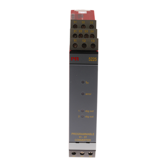
5 2 2 5
P r o g r a m m a b l e
f / I - f / f C o n v e r t e r
N o . 5 2 2 5 V 1 0 1 - I N ( 1 0 0 2 )
F r o m s e r . n o . 9 7 0 2 9 7 0 0 1
S I G N A L S T H E B E S T
Side 1
DK
Page 17
UK
Page 33
FR
Seite 49
DE
Advertisement
Chapters
Table of Contents

Subscribe to Our Youtube Channel
Related Manuals for PR 5225


Summary of Contents for PR 5225
- Page 1 Displays Programmable displays with a wide se- lection of inputs and outputs for display of temperature, volume and weight, etc. Feature linearisation, scaling, and difference measurement functions for programming via PReset software. Ex interfaces Interfaces analogue digital signals as well as HART signals between sensors / I/P ®...
-
Page 2: Table Of Contents
Adskillelse af system 5000 ..........Generelt ................Anvendelse ................. Teknisk karakteristik ............Indgang ................Analog udgang ..............Digital(e) udgang(e) ............. Relæudgange ..............Statusindikering ..............Elektriske specifikationer............ 10 Bestillingsskema ..............14 Blokdiagram ............... 14 5225 forbindelse til Loop Link ..........15... -
Page 3: Advarsel
SIGNATuRfORKLARING den lokale forhandler eller alternativt direkte til: PR electronics A/S, Lerbakken 10, 8410 Rønde, Danmark tlf: +45 86 37 26 77. Trekant med udråbstegn: Advarsel / krav. Hændelser der kan Installation og tilslutning af modulet skal følge landets gældende regler for føre til livstruende situationer. -
Page 4: Ef-Overensstemmelseserklæring
I det omfang, instruktionerne i denne manual ikke er nøje overholdt, vil kunden året: 1997 ikke kunne rette noget krav, som ellers måtte eksistere i henhold til den indgå- ede salgsaftale, mod PR electronics A/S. Rønde, 11. januar 2010 Kim Rasmussen... -
Page 5: Adskillelse Af System 5000
NPN- og PNP-udgang som generator: 0...20000 Hz --------------------------------------------------------------------------------------- GENERELT PRecon 5225 f/I - f/f konverteren konfigureres til den ønskede funktion ved hjælp af en standard PC og Loop Link programmeringskit. 5225 kan også leveres færdigkon figureret efter speci fikationer, se optionsindeks i databladet. -
Page 6: Teknisk Karakteristik
Samtidig f/I og f/f funktion gør det muligt, sammen med den analoge udgang, RELÆuDGANGE at have et skaleret digitalt udgangssignal. 5225 kan leveres med 2 relæudgange, som programmeres individuelt. STATuSINDIKERING frekvensgeneratorfunktionen anvendes f.eks. som time-base eller clock- 5225 har 4 lysdioder i fronten. -
Page 7: Elektriske Specifikationer
ELEKTRISKE SPEcIfIKATIONER Indgang: Generelt: Specifikationsområde: Måleområde ..........0...20 kHz -20°C til +60°C Min. måleområde ........0,001 Hz Max. nulpunktsforskydning (offset) .... 90% af valgt max. frekvens fælles specifikationer: Low cut off ..........0,001 Hz Forsyningsspænding ........19,2...28,8 VDC Min. impulsbredde (uden filter) ....25 µs Egetforbrug.......... - Page 8 TTL-indgang: frekvensgenerator: Trig-niveau LOW ......... ≤ 0,8 VDC Min. periodetid ........... 50 µs Trig-niveau HIGH ..........≥ 2,0 VDC Max. frekvens ..........20 kHz Indgangsimpedans ........≥ 100 kΩ Duty cycle ........... 50% S0-indgang efter DIN 43 864: Relæudgang: Trig-niveau LOW ......... ≤ 2,2 mA Isolation, test / drift ........
-
Page 9: Bestillingsskema
BESTILLINGSSKEMA 5225 fORBINDELSE TIL LOOP LINK Type Version udgang Forsyning 5225 Standard Analog + NPN / PNP Analog + relæudgang Loop Link BLOKDIAGRAM Komm. Komm. 5225 Indgang gnd. Forsyning +24 VDC Kommunikation 5 … 17 VDC Forsynings gnd. 5 … 17V+ Vreg. - Page 10 Technical characteristics ............ 25 Input ................... 25 Analogue output ..............25 Digital output(s) ..............26 Relay outputs ..............26 Status indication..............26 Electrical specifications ............27 Order .................. 31 Block diagram ..............31 5225 connection to Loop Link ........... 32...
-
Page 11: Warning
General mounting, connection and disconnection of wires. Troubleshooting the module. Repair of the module and replacement of circuit breakers must be done by PR electronics A/S only. WARNING SYSTEM 5000 must be mounted on DIN rail according to DIN 46277. The communication connector of SYSTEM 5000 is... -
Page 12: Safety Instructions
To the extent the instructions in this manual are not strictly observed, the custom er limits for ambient temperatures should be avoided by way of ventilation. cannot advance a demand against PR electronics A/S that would otherwise exist All modules fall under Installation Category II, Pollution Degree 1, and Insulation according to the concluded sales agreement. -
Page 13: Ec Declaration Of Conformity
As manufacturer First, remember to demount the connectors with hazardous voltages. By lifting PR electronics A/S the bottom lock, the module is detached from the DIN rail as shown in picture 1. Then, by lifting the upper lock and pulling the front plate simultaneously the PCB Lerbakken 10 is removed as shown in picture 2. -
Page 14: In General
IN GENERAL Short circuit-protected output. By way of a standard PC and the Loop Link programming kit, the PRecon 5225 When both current and voltage signals are used simultaneously, the mA loop to f/I - f/f Converter is configured acc. to the requested function. -
Page 15: Digital Output(S)
Communications interface ......Loop Link RELAy OuTPuTS Signal / noise ratio ........Min. 60 dB The PRecon 5225 can be delivered with 2 relay outputs that are programmed Response time, analogue ......< 60 ms + period individual ly. Response time, digital output ....< 50 ms + period STATuS INDIcATION Response time, concurrent f/I and f/f .. - Page 16 Input: TTL input: Trig-level LOW ..........≤ 0.8 VDC General: Trig-level HIGH ..........≥ 2.0 VDC Measurement range ........0...20 kHz Input impedance ........≥ 100 kΩ Min. measurement range ......0.001 Hz Max. offset..........90% of selected max. frequency S0 input acc.
-
Page 17: Order
Min. period ..........50 µs Max. frequency ........... 20 kHz Type Version Output Duty cycle ........... 50% 5225 Standard Analogue + NPN / PNP Relay output: Analogue + relay output Isolation, test / operation ......3.75 kVAC / 250 VAC Frequency max. -
Page 18: 5225 Connection To Loop Link
Sorties digitales : npn / pnp ou relais ........ 41 Sorties relais en option ............42 Indication d’état ..............42 Spécifications électriques ..........43 Référence de commande ........... 47 Schéma de principe ............47 Connexion entre le PR-5225 et le kit de programmation .. 48... -
Page 19: Avertissement
DIP et les cavaliers, montage général, raccordement et débranchement de fils et recherche de pannes sur le module. Seule PR electronics SARL est autorisée à réparer le module et à remplacer les dis joncteurs. AVERTISSEMENT Il convient de monter l’appareil SYSTEM 5000 sur un rail DIN en se conformant à... -
Page 20: Consignes De Sécurité
PR electronics SARL, même si cette dernière figure dans l’accord de electronics SARL, zac du chêne, Activillage, 4, allée des Sorbiers, f-69673 vente conclu. Bron cedex (tél. : (0) 472 140 607) ou à PR electronics A/S, Lerbakken 10, DK-8410 Rønde, Danemark (tél.:+45 86 37 26 77). -
Page 21: Déclaration De Conformité Ce
(voir déclare que le produit suivant : figure 3). Type : 5225 Nom : convertisseur programmable f/I - f/f correspond aux directives et normes suivantes : La directive CEM (EMC) 2004/108/CE et les modifications subséquentes EN 61326-1 Pour une spécification du niveau de rendement acceptable CEM (EMC) -
Page 22: Généralités
APPLIcATIONS La fonction f/I permet la conversion de fréquences en courant ou tension. De f/I - f/f 5225 plus, avec les sorties digitales, ce module peut être utilisé comme un contrôleur de fréquences (par exemple, en régulation de vitesse). La sortie analogique peut être programmée de telle sorte qu’elle reflète la période entre deux impulsions. -
Page 23: Sorties Relais En Option
NPN à la sortie PNP (borniers 22 à 23). Spécifications communes : SORTIES RELAIS EN OPTION Tension d’alimentation ....... 19,2...28,8 Vcc Le 5225 est disponible avec 2 sorties relais qui sont programmés indépendamment. Consommation interne ....... 1,7 W Consommation max........3,5 W Temporisation au démarrage INDIcATION D’ETAT... - Page 24 Décalage du zéro max....... 90% de la fréquence max. sélec. Sortie analogique Sortie courant : Cut off bas ..........0,001 Hz Gamme de signal ........0...20 mA Largeur d’impulsion min. (sans filtre) ..25 µs Période min. (sans filtre) ......50 µs Echelle min.
-
Page 25: Référence De Commande
CEM (EMC) 2004/108/CE ......EN 61326-1 Type Version Sortie DBT 2006/95/CE ........EN 61010-1 PELV/SELV ..........IEC 364-4-41 et EN 60742 5225 Standard Analogique + NPN / PNP Analogique + relais Ec = Echelle configurée ScHEMA DE PRINcIPE Entrée masse Communication en face avant Alim. -
Page 26: Connexion Entre Le Pr-5225 Et Le Kit De Programmation
PROGRAMMIERBARER f/I-f/f WANDLER cONNExION ENTRE LE PR-5225 ET LE KIT DE PROGRAMMATION PREcON TyP 5225 Alimentation INHALTSVERzEIcHNIS Warnung ................50 Sicherheitsregeln ..............52 EG-Konformitätserklärung ..........54 Loop Link Zerlegung des Systems 5000 ..........55 Allgemeines ................ 56 Comm. Verwendung ................ 56 Technische Merkmale ............ -
Page 27: Warnung
Überbrückern. Installation, Montage und Demontage von Leitungen. Fehlersuche im Modul. Reparaturen des Moduls und Austausch von Sicherungen dürfen nur von PR electronics A/S vorgenommen werden. WARNuNG Das System 5000 muss auf eine DIN-Schiene nach DIN 46277 montiert werden. Der Verbindungsstecker im SYSTEM 5000 ist an Eingangstermi- nale angeschlossen, in denen gefährliche Spannungen auftreten... -
Page 28: Sicherheitsregeln
Händler vor Ort Kontakt aufnehmen. Sie können aber auch direkt mit PR electronics GmbH, Im Erlengrund 26, D-46149 Oberhau- sen, (Tel.: (0) 208 62 53 09-0) oder mit PR electronics A/S, Lerbakken 10, DK-8410 Rønde, Dänemark (Tel. : +45 86 37 26 77) Kontakt aufnehmen. -
Page 29: Eg-Konformitätserklärung
DES SySTEMS 5000 Als Hersteller bescheinigt Zunächst ist gefährliche Spannung von den Anschlussklemmen zu trennen. Das PR electronics A/S Modul wird von der DIN-Schiene gelöst, indem man den unteren Verschluss löst, wie in Abb. 1 dargestellt. Die Platine wird daraufhin herausgenommen,... -
Page 30: Verwendung
Am Kontakteingang sollte man einen 50-Hz-Filter verwenden. ALLGEMEINES Das Gerät ist gegen Betrieb bei umgekehrter Polarität am Eingang und in der Der PRecon 5225 f/I - f/f-Wandler wird auf die gewünschte Funktion mit Hilfe Versorgung geschützt. eines Standard-PCs und des Loop Link-Programmiersatzes eingestellt. -
Page 31: Digital-Ausgang / -Ausgänge
Temperaturkoeffizi ent ......... < ±0,01% d. Messspanne / °C Ausgang verbindet (Überbrückungsstift 22-23). Linearitätsfehler .......... < ±0,1% d. Messspanne RELAISAuSGäNGE Einfluss von Änderung der 5225 kann mit 2 Relaisausgängen geliefert werden, die individuell program- Versorgungsspannung ........ < 0,002% d. Messspanne / %V mierbar sind. Hilfsspannungen: zuSTANDSANzEIGE NAMUR-Versorgung ........ - Page 32 Eingang: TTL-Eingang: Triggerniveau LOW ........≤ 0,8 VDC Allgemeines: Triggerniveau HIGH ......... ≥ 2,0 VDC Messbereich ..........0...20 kHz Eingangsimpedanz ........≥ 100 kΩ Min. Messbereich ........0,001 Hz Max. Nullpunktverschiebung (offset) ..90% der gewählten max. Frequenz S0-Eingang nach DIN 43 864: Untere Abschaltfrequenz ......
-
Page 33: Bestellangaben
BESTELLANGABEN Min. Periodendauer ........50 µs Maximalfrequenz ........20 kHz Version Ausgang Duty Cycle ..........50% 5225 Standard Analog + NPN / PNP Relaisausgang: Analog + Relaisausgang Isolationsspannung, Test / Betrieb ..... 3,75 kVAC / 250 VAC Maximalfrequenz........20 Hz Maximalspannung ........ -
Page 34: 5225 Verbindung Mit Loop Link
5225 VERBINDuNG MIT LOOP LINK Versorgung Loop Link Komm. 5225... - Page 35 Subsidiaries PR electronics A/S tilbyder et bredt program af analoge og digitale France signalbehandlingsmoduler til industriel automation. Programmet PR electronics Sarl Zac du Chêne, Activillage sales@prelectronics.fr består af Isolatorer, Displays, Ex-barrierer, Temperaturtransmittere, 4, allée des Sorbiers tel. +33 (0) 4 72 14 06 07 Universaltransmittere mfl.
Need help?
Do you have a question about the 5225 and is the answer not in the manual?
Questions and answers