
Related Manuals for turck IM12-FI01-1SF-1R


Summary of Contents for turck IM12-FI01-1SF-1R
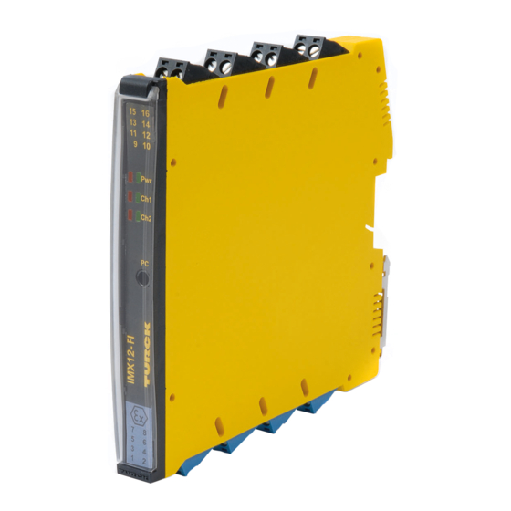
- Page 1 Your Global Automation Partner IM(X)12-FI01-1SF-1R Frequency Transducer Safety Manual...
- Page 2 Contents Hans Turck GmbH & Co. KG | T +49 208 4952-0 | F +49 208 4952-264 | more@turck.com | www.turck.com...
-
Page 3: Table Of Contents
Contents About this Document Scope Safety Integrity Level Product Description Safety function Safety accuracy Safe state Alarm state Safety Planning Architectural specifications Assumptions FMEDA results Examples for using the results 5.4.1 Probability of dangerous failure per hour (High Demand Mode) 5.4.2 Average probability of dangerous failure on demand (Low Demand Mode) Operation Instructions... - Page 4 Hans Turck GmbH & Co. KG | T +49 208 4952-0 | F +49 208 4952-264 | more@turck.com | www.turck.com...
-
Page 5: About This Document
All instructions must be followed in order to assure functional safety. Always make sure that this is the latest version of the safety manual at www.turck.com. The English version is considered the definitive document. Care was taken in the production of the translations of this document. -
Page 6: Product Description
– Relay output SPDT – monitoring overshoot/undershoot and window limits – working direction adjustable – reaction time digital output < 50 ms Hans Turck GmbH & Co. KG | T +49 208 4952-0 | F +49 208 4952-264 | more@turck.com | www.turck.com... -
Page 7: Safety Function
Safety function IMX12-FI01-1SF-1R The measured or monitored value at input [E1] are transmitted to the output [A1D] according to IM12-FI01-1SF-1R parameterization and within the local process safety time observing the permissible safety accuracy. Local process safety time is: ■ fin > 1,124 Hz: 1 s ■... -
Page 8: Safety Planning
All components that are not part of the safety function and cannot influence the safety func- tion (feedback immune) are excluded. ■ Only one input and one output are part of the safety function Hans Turck GmbH & Co. KG | T +49 208 4952-0 | F +49 208 4952-264 | more@turck.com | www.turck.com... -
Page 9: Fmeda Results
] SFF IMX12-FI01-1SF-1R 0 FIT 196.5 FIT 249.5 FIT 38 FIT 0 FIT 409.4 FIT 86,78 % 92.15 % IM12-FI01-1SF-1R 0 FIT 196.5 FIT 249.5 FIT 38 FIT 0 FIT 409.4 FIT 86,78 % 92.15 % The stated Safe Failure Fraction (SFF) is for reference only. The complete subsystem will need to be evaluated to determine the overall SFF. -
Page 10: Average Probability Of Dangerous Failure On Demand (Low Demand Mode)
8760 h MTTR 24 h Digital output PFDavg IMX12-FI01-1SF-1R 1.73E-04 IM12-FI01-1SF-1R 1.73E-04 Hans Turck GmbH & Co. KG | T +49 208 4952-0 | F +49 208 4952-264 | more@turck.com | www.turck.com... -
Page 11: Operation Instructions
During operation of the device, surface temperatures may occur that could lead to burns if ➤ touched. The device must not be repaired. If problems occur with regard to functional safety, Turck ➤ must be notified immediately and the device must be returned immediately to: Hans Turck GmbH &... -
Page 12: Before Operation
Fasten the screws with a screwdriver (max. tightening torque 0.5 Nm) to affix the cable ends. ➤ 0.2…2.5 mm (24…13 AWG) 7 mm 0.5 Nm (4.43 LBS-inc) Fig. 2: Connection with screw terminals Hans Turck GmbH & Co. KG | T +49 208 4952-0 | F +49 208 4952-264 | more@turck.com | www.turck.com... - Page 13 Connection with spring-type terminals Push the opening lever with a suitable screwdriver. ➤ Insert the stripped cable ends (7 mm) in the guides of the spring-type terminals. ➤ Pull the screwdriver to fix the cable ends. ➤ 0.2…2.5 mm (24…13 AWG) 7 mm Fig.
-
Page 14: Parameterization
Function Relay Loc OFF/ON OFF/ON Locked switching LocOn/Locoff Locked On/Locked Off SUD Input [E2]/[E3] Input [E2]/input [E2] SUD mode Dyn/Stat Dynamic/Static Hans Turck GmbH & Co. KG | T +49 208 4952-0 | F +49 208 4952-264 | more@turck.com | www.turck.com... - Page 15 Rotary switches: D] switching point Hysteresis [%] 15.0 17.5 12.5 D] ON / OFF delay [s] 0.5/0.5 0.75/0.75 0/0.75 0/0.5 0.5/0 1.0/0 0.75/0 D] SUD [s] 60 90 [kHz] 10 15 -3 -2 Config The function on/off delay is not part of the safety function and must be set to 0 s. [A1D] switching point: G = (M1 * 100 + M2 * 10 + M3 * 1) * 10 Example 1: 321 mHz: M1 = 3, M2 = 2, M1 = 1;...
- Page 16 The value of this parameter speci- 0.0, 0.5, 0.75, 1.0 s fies the switch off delay after detec- tion of switch on condition. Hans Turck GmbH & Co. KG | T +49 208 4952-0 | F +49 208 4952-264 | more@turck.com | www.turck.com...
-
Page 17: Parameter Check
Inversion Selection Description Activated This function enables the inversion of the switching state (instead of off, on and vice versa). Deactivated If the inversion function is disabled, the switching state is transferred to the digital output A1D without inversion according to the parameter setting. -
Page 18: Operation
0,5 1 Fig. 6: Output relay load curve The connection of a deactivated input is unnecessary. Hans Turck GmbH & Co. KG | T +49 208 4952-0 | F +49 208 4952-264 | more@turck.com | www.turck.com... -
Page 19: After Operation
After operation Undo the terminal connection on the device. ➤ Remove the device from its rail fixing as shown in the figure: ➤ Fig. 7: Remove device Ensure the dispose of the device. ➤ V01.00 | 2020/04... -
Page 20: Appendix: Connection And Wiring Diagrams
YE/RD 6 – Common NAMUR only Pwr/Err Alarm 15 + Output 10…30 VDC GN/RD 16 – X1X2 X3 X4 – Hans Turck GmbH & Co. KG | T +49 208 4952-0 | F +49 208 4952-264 | more@turck.com | www.turck.com... -
Page 21: Appendix: Terms And Abbreviations
IM12-FI01-1SF-1R 1 2 3 4 5 8 – YE/RD NAMUR 13 + 14 – only 0…3 VDC / 2 – 10…30 VDC 0: 0…3 VDC PNP/ 1: 5…30 VDC YE/RD no line monitoring Common Pwr/Err Alarm 15 + Output 10…30 VDC 6 –... -
Page 22: Appendix: Proof Test
Once the test has been completed, document and archive the results. Appendix: Document History Document version Date Modifications 2020-04-07 Initial version Hans Turck GmbH & Co. KG | T +49 208 4952-0 | F +49 208 4952-264 | more@turck.com | www.turck.com... - Page 23 V01.00 | 2020/04...
- Page 24 Over 30 subsidiaries and over 60 representations worldwide! 100017761 | 2020/04 *100017761* www.turck.com...
Need help?
Do you have a question about the IM12-FI01-1SF-1R and is the answer not in the manual?
Questions and answers