Table of Contents
Advertisement
Quick Links
IMX12-FI01-1SF-1I1R...
DE
Kurzbetriebsanleitung
IMX12-FI01-1SF-1I1R...
Weitere Unterlagen
Ergänzend zu diesem Dokument finden Sie im Internet unter
www.turck.com
Unterlagen:
■
Datenblatt
■
Sicherheitshandbuch
■
Zulassungen
■
Konformitätserklärungen
Zu Ihrer Sicherheit
Bestimmungsgemäße Verwendung
Die Frequenzmessumformer/Puls-Counter der Baureihe IMX12-FI01-1SF-1I1R... sind mit ei-
gensicheren Eingangskreisen ausgestattet und übertragen Frequenzsignale bis 20.000 Hz gal-
vanisch getrennt aus dem explosionsgefährdeten Bereich in den sicheren Bereich. Zusätzlich
können mit den Geräten Grenzwerte, Schlupf oder Rechts-/Links-Lauf überwacht werden. Die
Geräte sind für den Betrieb in Zone 2 geeignet. Mit den Geräten lassen sich auch sicherheits-
gerichtete Anwendungen bis einschließlich SIL2 (High- und Low-Demand gemäß IEC 61508)
aufbauen (Hardwarefehlertoleranz HFT = 0).
GEFAHR
Die vorliegende Anleitung enthält keine Informationen zum Einsatz in sicherheitsgerichteten
Anwendungen.
Lebensgefahr durch Fehlanwendung!
Bei Einsatz in sicherheitsgerichteten Systemen: Halten Sie unbedingt die Vorschriften des
zugehörigen Sicherheitshandbuchs ein.
Die Geräte dürfen nur wie in dieser Anleitung beschrieben verwendet werden. Jede andere
Verwendung gilt als nicht bestimmungsgemäß. Für daraus resultierende Schäden übernimmt
Turck keine Haftung.
Allgemeine Sicherheitshinweise
■
Nur fachlich geschultes Personal darf das Gerät montieren, installieren, betreiben, paramet-
rieren und instand halten.
■
Das Gerät erfüllt die EMV-Anforderungen für den industriellen Bereich. Bei Einsatz in Wohn-
bereichen Maßnahmen treffen, um Funkstörungen zu vermeiden.
Hinweise zum Ex-Schutz
■
Gerät nur mit geeignetem Schutzgehäuse im Ex-Bereich einsetzen.
■
Nationale und internationale Vorschriften für den Explosionsschutz beachten.
■
Bei Einsatz des Gerätes in Ex-Kreisen muss der Anwender über Kenntnisse im Explosions-
schutz (IEC/EN 60079-14 etc.) verfügen.
■
Das Gerät nur innerhalb der zulässigen Betriebs- und Umgebungsbedingungen (siehe
Zulassungsdaten und Auflagen durch die Ex-Zulassung) einsetzen.
Auflagen durch die Ex-Zulassungen bei Einsatz in Zone 2
■
Gerät in ein Gehäuse nach IEC/EN 60079-0 mit einer Schutzart mind. IP54 nach IEC/EN 60529
montieren.
■
Gerät nur in Bereichen mit einem Verschmutzungsgrad von maximal 2 einsetzen.
■
Nicht eigensichere Stromkreise nur trennen und verbinden, wenn keine Spannung anliegt.
Produktbeschreibung
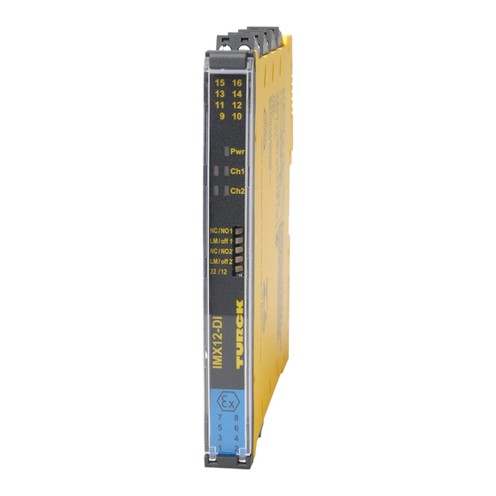
Geräteübersicht
siehe Abb. 1: Frontansicht, Abb. 2: Abmessungen, Abb. 3: Power-Bridge-Verbinder, Abb. 8 und
Abb. 9: Anschlussklemmen
Funktionen und Betriebsarten
Die Frequenzmessumformer/Puls-Counter IMX12-FI01-1SF-1I1R... sind einkanalig ausgelegt
und verfügen über zwei eigensichere Eingänge zum Anschluss von Sensoren nach EN 60947-5-
6 (NAMUR) oder potenzialfreien Kontakten. Ausgangsseitig sind ein Stromausgang 0/4...20 mA
und ein Schließer-Relais vorhanden. Die Geräte werden über FDT und IODD mit einem PC
parametriert. Der Stromausgang kann (wahlweise als Quelle oder Senke) auf 0/4...20 mA
eingestellt werden. Die Eingangssignale werden der Parametrierung entsprechend (E1, E2,
E1 - E2 oder E2 - E1) als normiertes Stromsignal 0/4...20 mA ausgegeben. Mit dem Relaisaus-
gang kann ein Messwert auf Über- oder Unterschreitung eines Grenzwertes oder auf Verlassen
eines Grenzwert-Fensters überwacht werden. Die Anlaufüberbrückung SUD (Start Up Delay)
wird über Eingang E1, E2 oder E3 eingeschaltet. Die Geräte mit Power-Bridge-Anschluss bieten
zusätzlich die Möglichkeit, eine Sammelstörmeldung zu übertragen.
Montieren
GEFAHR
Explosionsfähige Atmosphäre
Explosion durch zündfähige Funken!
Bei Einsatz in Zone 2:
Gerät nur montieren und anschließen, wenn keine explosionsfähige Atmosphäre
vorliegt.
Gerät in ein Gehäuse nach IEC/EN 60079-0 mit einer Schutzart von mind. IP54 montieren
Bei der Montage darauf achten, dass in diesem Gehäuse die zulässige Betriebstempera-
tur des Geräts auch bei ungünstigen Umgebungsbedingungen nicht überschritten wird.
Montieren auf Hutschiene ohne Power-Bridge-Verbinder
Gerät gemäß Abb. 4 befestigen.
Montieren auf Hutschiene mit Power-Bridge-Verbinder
Gerät gemäß Abb. 5 montieren.
FR
Guide d'utilisation rapide
IMX12-FI01-1SF-1I1R...
Documents complémentaires
folgende
Ce document est complété par les documents suivants, disponibles sur notre site Web
www.turck.com :
■
Fiche technique
■
Manuel de sécurité
■
Homologations
■
Déclarations de conformité
Pour votre sécurité
Utilisation conforme
Les convertisseurs de fréquence/Puls-Counter de la série IMX12-FI01-1SF-1I1R... sont équipés
de circuits d'entrée à sécurité intrinsèque et transmettent les signaux de fréquence jusqu'à
20 000 Hz de manière séparée galvaniquement depuis la zone présentant un risque d'explosion
à la zone sécurisée. En outre, les appareils peuvent surveiller les valeurs limites, le patinage ou
la rotation droite/gauche. Les appareils sont conçus pour un fonctionnement en zone 2. Des
applications de sécurité jusqu'à SIL2 compris (High- et Low-Demand selon CEI 61508) peuvent
également être montées avec les appareils (Tolérance aux pannes hardware HFT = 0).
DANGER
La notice fournie ne contient aucune information sur l'utilisation avec des applications de
sécurité.
Risque de mort en cas de mauvaise utilisation !
En cas d'utilisation avec des systèmes de sécurité, respectez impérativement les direc-
tives du manuel de sécurité correspondant.
Les appareils doivent exclusivement être utilisés conformément aux indications figurant dans
la présente notice. Toute autre utilisation est considérée comme non conforme. La société Turck
décline toute responsabilité en cas de dommages causés par une utilisation non conforme.
Consignes générales de sécurité
■
Seul un personnel qualifié est habilité à monter, installer, utiliser, paramétrer et entretenir
l'appareil.
■
L'appareil répond aux exigences CEM pour le domaine industriel. En cas d'utilisation dans
des zones résidentielles, prendre des mesures pour éviter les interférences radio.
Remarques sur la protection Ex
■
Utilisez toujours l'appareil avec un carter de protection adapté dans la zone Ex.
■
Respectez les directives nationales et internationales en matière de protection contre les
explosions.
■
Pour toute utilisation en milieu Ex, l'opérateur doit posséder des connaissances en matière
de protection contre les explosions (CEI/EN 60079-14, etc.).
■
Utilisez l'appareil uniquement dans les conditions ambiantes et de fonctionnement autori-
sées (voir données d'autorisation et exigences de l'homologation Ex).
Exigences relatives aux certificats Ex en cas d'utilisation en zone 2
■
Montez l'appareil dans un carter conformément à la norme CEI/EN 60079-0 avec un indice
de protection IP54 minimum, conformément à la norme CEI/EN 60529.
■
Utilisez l'appareil uniquement dans des zones présentant un degré de salissure de 2 au
maximum.
■
Les circuits à sécurité électrique non intrinsèque doivent être séparés et raccordés unique-
ment lorsqu'aucune tension n'est présente.
Description du produit
Aperçu de l'appareil
voir fig. 1 : Vue avant, fig. 2 : Dimensions, voir fig. 3 : Connecteur de Bridge d'alimentation, voir
fig. 8 et fig. 9 : Bornes de raccordement
Fonctions et modes de fonctionnement
Les convertisseurs de fréquence/Puls-Counter IMX12-FI01-1SF-1I1R... ont un canal unique et
disposent de deux entrées de sécurité intrinsèque pour le raccordement de capteurs conformé-
ment à la norme EN 60947-5-6 (NAMUR) ou de contacts secs. Une sortie électrique 0/4...20 mA
et un relais de contact à fermeture sont disponibles côté sortie. Les appareils sont paramétrés
sur un PC via FDT et IODD. La sortie électrique peut (au choix, en tant que source ou collecteur)
être réglée sur 0/4...20 mA. Les signaux d'entrée sont émis en tant que signal électrique
normalisé 0/4...20 mA, conformément au paramétrage (E1, E2, E1 - E2 ou E2 - E1). Avec la sortie
relais, une valeur mesurée peut être surveillée en cas de dépassement ou de sous-dépasse-
ment d'une valeur limite, ou pour quitter une fenêtre de valeurs limites. La temporisation de
démarrage (Start Up delay, SUD) est activée via l'entrée E1, E2 ou E3. Les appareils équipés d'un
raccordement de Bridge d'alimentation permettent en outre de transmettre un message de
défaut groupé.
Installation
DANGER
Atmosphère explosive
Explosion par étincelles inflammables !
En cas d'utilisation en zone 2 :
Montez et raccordez l'appareil uniquement si l'atmosphère n'est pas explosive.
Montez l'appareil dans un carter selon la norme CEI/EN 60079-0 avec un type de protec-
tion au min. IP54.
Lors du montage, la température de l'appareil dans ce carter ne doit pas dépasser sa tem-
pérature en fonctionnement maximale autorisée, même dans des conditions ambiantes
défavorables.
Montage sur profilé chapeau sans connecteur de Bridge d'alimentation
Fixez l'appareil conformément à la fig. 4.
Montage sur profilé chapeau avec connecteur de Bridge d'alimentation
Montez l'appareil conformément à la fig. 5.
EN
Quick Start Guide
IMX12-FI01-1SF-1I1R...
Other documents
Besides this document, the following material can be found on the Internet at www.turck.com:
■
Data sheet
■
Safety manual
■
Approvals
■
Declarations of conformity
For your safety
Intended use
The frequency transducers/pulse counters in the IMX12-FI01-1SF-1I1R... series are equipped
with intrinsically safe input circuits and transfer frequency signals up to 20,000 Hz from the Ex
area to the non-Ex area such that the signals are galvanically isolated. The devices can also be
used to monitor limit values, slippage or clockwise/counter-clockwise rotation. The devices are
suitable for use in Zone 2. The devices allow safety-oriented applications up to and including
SIL2 (high demand and low demand in accordance with IEC 61508) to be constructed (Hard-
ware fault tolerance HFT = 0).
DANGER
These instructions do not contain any information about use in safety-oriented applications.
Risk to life due to improper use!
When using the device in safety-oriented systems: In all cases comply with the provisions
of the corresponding safety manual.
The devices must only be used as described in these instructions. Any other use is not in ac-
cordance with the intended use. Turck accepts no liability for any resulting damage.
General safety instructions
■
The device may only be assembled, installed, operated, parameterized and maintained by
professionally trained personnel.
■
The device meets the EMC requirements for industrial areas. When used in residential areas,
take measures to prevent radio interference.
Explosion protection notes
■
Never use the device in Ex areas without the appropriate protective enclosure fitted.
■
Adhere to national and international regulations on explosion protection.
■
When using the device in explosion-protection circuits, the user must have a working knowl-
edge of explosion protection (IEC/EN 60079-14 etc.).
■
Use the device only within the permitted operating and environmental conditions (see
registration data and conditions from the Ex approval).
Requirements for Ex approval for use in Zone 2
■
Install the device in an enclosure in accordance with IEC/EN 60079-0 with a protection type
of at least IP54 in accordance with IEC/EN 60529.
■
Use the device only in areas with a contamination level of no higher than 2.
■
Only disconnect and connect non-intrinsically safe electrical circuits if no voltage is applied.
Product description
Device overview
See fig.1: front view, fig. 2: dimensions, fig. 3: Power-Bridge connector, fig. 8 and
fig. 9: terminals
Functions and operating modes
The IMX12-FI01-1SF-1I1R... frequency transducers/pulse counters feature a single channel
and have two intrinsically safe inputs for connecting sensors in accordance with EN 60947-5-6
(NAMUR) or potential-free contacts. On the output side, there is a 0/4...20 mA current output
and a normally open relay. The devices are parameterized via FDT and IODD using a PC. The
current output can be set (either as source or sink) to 0/4...20 mA. The input signals are output
as a normalized current signal from 0/4...20 mA according to the parameterization (E1, E2,
E1 - E2 or E2 - E1). With the relay output, a measured value can be monitored for exceeding or
falling below a limit value or leaving a limit value window. The start-up delay (SUD) is activated
via input E1, E2 or E3. The devices with a Power Bridge connection also offer the possibility of
transmitting a collective fault message.
Installing
DANGER
Potentially explosive atmosphere
Risk of explosion through spark ignition!
Installation in Zone 2:
Assemble and connect the device only if the atmosphere is not potentially explosive
Install the device in an enclosure in accordance with IEC/EN 60079-0 with a protection
type of at least IP54.
When installing, ensure that the permissible operating temperature for the device will
not be exceeded in this enclosure, even in unfavorable ambient conditions
Installing the device on a DIN rail without a Power-Bridge connector
Attach the device in accordance with fig. 4
Installing the device on a DIN rail with a Power-Bridge connector
Install the device in accordance with fig. 5
IMX12-FI01-1SF-1I1R...
Frequency Transducer/Pulse Counter
Quick Start Guide
Doc. no. 100000260
Additional
information see
turck.com
①
②
15 16
13 14
11 12
9 10
Power
Pwr
128
Fault
Ch1
Status
Ch2
110
Rel
PC
120
7
8
5
6
3
4
1
2
③
④
⑤
17,7
1
36,3
19,4
⑥
⑦
16
10
15
9
X5
X4
X3
X2
X1
2
8
1
7
⑧
⑨
⑩
0.2...2.5 mm
2
0.2...2.5 mm
2
(24...13 AWG)
(24...13 AWG)
15 16
15 16
13 14
13 14
11 12
11 12
9 10
9 10
Pwr
Pwr
2
1
Ch1
1
Ch2
1
7 mm
7 mm
2
0.5 Nm
(4.43 LBS-inc)
7
7
8
8
5
5
6
6
3
3
4
4
1
1
2
2
≥ 50 mm
Wiring diagrams
to PC via
µP
USB-2-IOL-0002
+
–
II
I
9
E1, A1A
0/4...20 mA
Source / Sink
YE/RD
–
+
BN
10
7 +
E1
BU
11 +
8 –
E2
NAMUR
YE/RD
12 –
SUD
BN
5 +
13
E2
A1D
BU
A1D
6 –
YE/RD
14
NAMUR
Pwr/Err
15 +
GN/RD
10...30 VDC
16 –
NC
X1 X2 X3
X4
X5
+
–
IMX12-FI01-1SF-1I1R-CPR...
© Hans Turck GmbH & Co. KG | 100000260 2023-06
12.5
2
15 16
15 16
15 16
15 16
15 16
15 16
13 14
13 14
13 14
13 14
13 14
13 14
11 12
11 12
11 12
11 12
11 12
11 12
9 10
9 10
9 10
9 10
9 10
9 10
Pwr
Pwr
Pwr
Pwr
Pwr
Pwr
1
Ch1
Ch1
1
Ch1
1
Ch2
Ch2
Ch2
7
7
8
8
7
7
8
8
7
7
8
8
5
5
6
6
5
5
6
6
5
5
6
6
3
3
4
4
3
3
4
4
3
3
4
4
1
1
2
2
1
1
2
2
1
1
2
2
≥ 6 mm
3 mm
A1A
E3
0: 0...3 VDC
1: 10...30 VDC
Advertisement
Table of Contents

Related Manuals for turck IMX12-FI01-1SF-1I1R Series


Summary of Contents for turck IMX12-FI01-1SF-1I1R Series
- Page 1 Ergänzend zu diesem Dokument finden Sie im Internet unter www.turck.com folgende Ce document est complété par les documents suivants, disponibles sur notre site Web Besides this document, the following material can be found on the Internet at www.turck.com: ■ www.turck.com : Unterlagen: Data sheet ■...
- Page 2 = 253 VAC/VDC Hans Turck GmbH & Co. KG | Witzlebenstraße 7, 45472 Mülheim an der Ruhr, Germany | Tel. +49 208 4952-0 | Fax +49 208 4952-264 | more@turck.com | www.turck.com © Hans Turck GmbH & Co. KG | 100000260 2023-06...
- Page 3 Solo se autoriza el uso de los dispositivos conforme a las indicaciones de esta guía. Cualquier 该装置符合工业领域的EMC要求。 在住宅区使用时, 请采取措施以防止无线电干扰。 12.5 considerado impróprio e a Turck não se responsabilizará por danos resultantes. otro uso se considera no previsto, y Turck no asumirá responsabilidad alguna de los daños que 防爆说明 ■ ③...
- Page 4 = 253 VAC/VDC Hans Turck GmbH & Co. KG | Witzlebenstraße 7, 45472 Mülheim an der Ruhr, Germany | Tel. +49 208 4952-0 | Fax +49 208 4952-264 | more@turck.com | www.turck.com © Hans Turck GmbH & Co. KG | 100000260 2023-06...
- Page 5 účelu použití tohoto výrobku; společnost Turck nepřebírá odpovědnost za případně 12.5 que altro utilizzo è inteso come non conforme, Turck non si assume quindi nessuna responsabi- Urządzenia mogą być używane wyłącznie w sposób opisany w niniejszej instrukcji. Inne spo- vzniklé...
- Page 6 = 253 VAC/VDC Hans Turck GmbH & Co. KG | Witzlebenstraße 7, 45472 Mülheim an der Ruhr, Germany | Tel. +49 208 4952-0 | Fax +49 208 4952-264 | more@turck.com | www.turck.com © Hans Turck GmbH & Co. KG | 100000260 2023-06...
- Page 7 Другие документы Additional 本書の他にも、 以下の資料がインターネッ ト上 (www.turck.com) にあります。 ■ 이 문서 외에도 다음과 같은 자료를 인터넷(www.turck.com)에서 확인할 수 있습니다. information see Этот документ и следующие материалы доступны в Интернете по адресу www.turck.com: ■ データシート 데이터 시트 ■ ■ Техническое описание...
- Page 8 = 253 VAC/VDC Hans Turck GmbH & Co. KG | Witzlebenstraße 7, 45472 Mülheim an der Ruhr, Germany | Tel. +49 208 4952-0 | Fax +49 208 4952-264 | more@turck.com | www.turck.com © Hans Turck GmbH & Co. KG | 100000260 2023-06...
Need help?
Do you have a question about the IMX12-FI01-1SF-1I1R Series and is the answer not in the manual?
Questions and answers