
Related Manuals for YOKOGAWA FU20-FTS


Summary of Contents for YOKOGAWA FU20-FTS
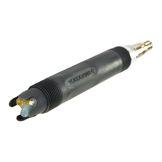
- Page 1 Model FU20-FTS/MTS Instruction Differential pH/ORP sensor Manual IM 12B06J03-05EN-P edition...
- Page 2 родния ви eзик, ce свържете c най- artículos antiexplosivos en su idioma local, близкия oфис или представителство на deberá ponerse en contacto con la oficina фирма Yokogawa. o el representante de Yokogawa más cercano. (CZ) Všechny uživatelské příručky pro výrobky, na něž se vztahuje nevýbušné schváleni Tous les manuels d’instruction des...
- Page 3 Ex, deverá entrar em contacto com a delegação mais próxima (SLO) ou com um representante da Yokogawa. Vsi predpisi in navodila za AEX Ex sorodni pridelki so pri roki v anglišèini. Èe so Ex sorodna navodila potrebna v vašem tukejnjem jeziku, kontaktirajte vaš...
-
Page 4: Table Of Contents
3.2 Preparing the sensor for use ................21 3.3 Mounting the sensor ..................21 3.4 Mounting FU20-FTS/MTS using quick removal adapters ......22 3.5 Mounting the FU20-FTS/MTS in PR10 retractable ........... 23 4. DIMENSIONS......................25 5. WIRING ........................26 6. GENERAL CALIBRATION & MAINTENANCE PROCEDURE ........27 6.1 Calibration for pH measurement ............... -
Page 5: Preface
WU10- cable or halogen free information for the installation and use WE10- cable. Both cables are available in of the FU20-FTS and FU20-MTS, four-in- different lengths. one wide body pH sensors. Like the other members of the FU20 family the... -
Page 6: Warranty And Service
1.3 Warranty and Service 1.4 Serial number Yokogawa products and parts are The Serial number is defined by nine (9) guaranteed free from defects in alphanumeric characters: workmanship and material under normal Production location use and service for a period of (typically) -
Page 7: General Specifications
: 0 ± 15 mV Slope : > 90 % in pH 2-12 with pH = pNa+2 (of theoretical value) Note: The temperature sensor included in the FU20-FTS-MTS is designed for process compensation and for indication. It is NOT designed for process temperature control. -
Page 8: Shipping Details
2.6 Shipping details FU20-FTS/MTS Package size (L x W x H) : 300 x 100 x 75 mm (11.8 x 3.9 x 3.0 inch) Package weight (max.) : 0.33 kg (0.73 lbs) 2.7 Environmental conditions Storage temperature : -10 to +50 ºC (14 to 122 ºF) -
Page 9: Regulatory Standards
Note 1: Models without ID-chip (with fixed cable or VP type): I/O signals are from/to an associated intrinsically safe certified pH/ORP transmitter (e.g. Yokogawa transmitter Model FLX21/FLX202 series or Yokogawa transmitter Model PH202S series). Models with ID-chip (VS type): I/O signals are from/to an associated intrinsically safe certified pH/ORP transmitter, Yokogawa Smart Adapter Model SA11-P1. - Page 10 When the sensor has been connected to non intrinsically safe equipment which exceeds the restrictions regarding the sensor input circuits, the sensor is not suitable anymore for intrinsically safe use. Note 2: Ambient temperature: -40 °C to +40 °C for temperature class T6, -40 °C to +55 °C for temperature class T4 and T5, -40 °C to +105 °C for temperature class T3.
- Page 11 FM-United States Applying standards : FM Class 3600 FM Class 3610 FM Class 3810 ANSI/ISA 60079-0 ANSI/ISA 60079-11 Certificate no.* : FM20US0123X IS CL I, DIV 1, GP ABCD, T3…T6 CL I, ZN 0, AEx ia IIC, T3…T6 Ga Control Drawing: D&E 2020-023-A50 Electrical data : See Note 3 Specific conditions : See Control Drawing D&E 2020-023-A50...
- Page 12 Control drawing: D&E 2020-023-A50 (part 1) IM 12B06J03-05EN-P...
- Page 13 Remarks: No revision to this drawing without prior approval of FM. Installation must be in accordance with the National Electrical Code (ANSI/NFPA 70), ANSI/ISA-RP12.06.01, and relevant local codes. The sensor shall be installed to a certified intrinsically safe HOST with the following maximum values: Uo= 18 V, Io = 170 mA, Po = 400 mW.
- Page 14 Control drawing: D&E 2020-023-A50 (part 2) IM 12B06J03-05EN-P...
- Page 15 Remarks: No revision to this drawing without prior approval of FM. Installation must be in accordance with the National Electrical Code (ANSI/NFPA 70), ANSI/ISA-RP12.06.01, and relevant local codes. The sensor shall be installed to a certified intrinsically safe Smart Adapter, model SA11-P2 with the following maximum values: Uo= 6.6 V, Io = 100 mA, Po = 165 mW.
- Page 16 FM-Canada Applying standards : CAN/CSA-C22.2 No. 60079-0 CAN/CSA-C22.2 No. 60079-11 Certificate no.* : FM20CA0062X IS CL I, DIV 1, GP ABCD, T3…T6 CL I, ZN 0, Ex ia IIC, T3…T6 Ga Control Drawing: D&E 2020-023-A51 Electrical data : See Note 4. Specific conditions of use : See Control Drawing D&E 2020-023-A51.
- Page 17 Control drawing: D&E 2020-023-A51 (part 1) IM 12B06J03-05EN-P...
- Page 18 Remarks: No revision to this drawing without prior approval of FM. Installation must be in accordance with the Canadian Electrical Code (CEC) CSA22.1, and relevant local codes. The sensor shall be installed to a certified intrinsically safe HOST with the following maximum values: Uo= 18 V, Io = 170 mA, Po = 400 mW.
- Page 19 Control drawing: D&E 2020-023-A51 (part 2) IM 12B06J03-05EN-P...
- Page 20 Remarks: No revision to this drawing without prior approval of FM. Installation must be in accordance with the Canadian Electrical Code (CEC) CSA22.1, and relevant local codes. The sensor shall be installed to a certified intrinsically safe Smart Adapter, model SA11-P2 with the following maximum values: Uo= 6.6 V, Io = 100 mA, Po = 165 mW.
-
Page 21: Installation Of
3.2 Preparing the sensor for use For optimum measurement results, the Remove the sensor from its shipping box FU20-FTS/MTS should be installed in a and slide of the so-called ‘wet pocket’, the location that offers an acceptable tube filled with solution to prevent drying... -
Page 22: Mounting Fu20-Fts/Mts Using Quick Removal Adapters
4 Place the O-ring and screw the mating The FU20-FTS/MTS can also be mounted part of the adapter on the sensor; using one of the optional quick-removal 5 Mount the sensor in the adapter, making adapters (/NSS, /NTI, /BSS, /BTI, see sure that the O-ring seals properly;... -
Page 23: Mounting The Fu20-Fts/Mts In Pr10 Retractable
5 Lead the sensor cable through the tube 3.5 Mounting the FU20-FTS/MTS in of the fitting, from the side where the PR10 retractable knurled knob has been removed. Attach 1 Take the sensor out of the box and the sensor and cable as usual. - Page 24 FU20 + FD40 FU20 + adapter Process flow Fitting /HCNF, SPRAY CLEANER O-ring Cleaning solution (water, acid, etc) Adapter (/FPS) K1547PH FU20 K1547PF O-ring 60mm Figure 7: Installation examples for the FU20 IM 12B06J03-05EN-P...
-
Page 25: Dimensions
4. DIMENSIONS Dimensions in mm (inches) Figure 8: Dimensions FU20-FTS/MTS /NSS, /NTI, /BSP, BTI /FPS Figure 9: Dimensions 1” FU20-FTS/MTS adapter Stainless Steel & Titanium and FU20 -FTS/MTS adapter for FF40, FS40 and FD40 fittings IM 12B06J03-05EN-P... -
Page 26: Wiring
5. WIRING The FU20-FTS/MTS sensor is provided with a 8 pins Vario Pin connector (type VP without ID-chip and type VS with ID-chip). Figure 10: Cable layout Figure 11: Connector layout Table 7: Description Description VP type VS type Reference... -
Page 27: General Calibration & Maintenance Procedure
6. GENERAL CALIBRATION & MAINTENANCE PROCEDURE Calibration of the FU20-FTS/MTS sensor has to be done with the pH analyzer connected. Normally the pH standards that are preprogrammed in the pH analyzer can be used for calibration with the pH analyzer set to “AUTOCAL”. The FU20-FTS/MTS however is a differential pH sensor which needs pH buffers that have the same ionic strength because the sodium reference will change as the ionic strength changes. -
Page 28: Calibration Of Orp And Rh Measurements
Instruction Manual of the analyzer. The rH value is a function of the reference system and the pH value of the buffer solution. The FU20-FTS/MTS sensor has a reference system of 1molal Silver/Silver Chloride (Ag/AgCl). The commonly used standards for ORP and rH calibration are made from Chinhydron (Quinhydrone) powder dissolved in pH buffer solutions (1g / 200 ml). -
Page 29: Model Codes
7. MODEL CODES Table 9: Model Option Suffix code Description Code code FU20 Wide body sensor Fixed cable, 3 meter not available Fixed cable, 5 meter for FTD, FTS Fixed cable, 10 meter Type & MTS Fixed cable, 20 meter Variopin connector →... -
Page 30: Spare Parts
8. SPARE PARTS Table 10: Spare part Description FU20 /FPS Adapter for FF40, FS40 and FD40 fittings K1523DD (PPO) /NSS 1” NPT, Stainless Steel adapter (Viton O-ring) K1547PK /BSS ISO 7/1-R1, Stainless Steel adapter K1547PL (Viton O-ring) /NTI 1” NPT, Titanium adapter (Viton O-ring) K1547PM K1547PN /BTI ISO 7/1-R1, Titanium adapter (Viton O-ring) -
Page 31: Chemical Compatibility Chart
9. CHEMICAL COMPATIBILITY CHART Table 11: Note : Information in this list is based on our general experience and literature data and given in good faith. However, Yokogawa is unable to accept responsibility for claims related to this information. IM 12B06J03-05EN-P... - Page 32 IM 12B06J03-05EN-P Printed in The Netherlands, 01-2101 Subject to change without notice Copyright © IM 12B06J03-05EN-P...
Need help?
Do you have a question about the FU20-FTS and is the answer not in the manual?
Questions and answers