
Subscribe to Our Youtube Channel
Summary of Contents for Viavi SmartClass MPOLS-84
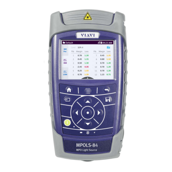
- Page 1 MPOLS-84 (P) MPOLS-85 (P) MPOLP-85 (P) SmartClass™ Fiber Multifiber Light Source Multifiber Power Meter Operating manual BN 2329/98.21 2019.12 English...
- Page 2 430 N. McCarthy Blvd. • Milpitas, CA 95035 USA Copyright © Copyright 2019 Viavi Solutions Inc. All rights reserved. Viavi and the Viavi logo are trademarks of Viavi Solutions Inc. All other trademarks and registered trademarks are the properties of their respective owners.
-
Page 3: Table Of Contents
ONTENTS ONTENTS ....... . . 6 NTRODUCTION Enterprise Structured Cabling Workflow....6 MPOLx-84/85 (P) MPO Test Sets . - Page 4 ONTENTS ....45 ENGTH PERATION General information....... . . 45 Adjusting general test settings .
- Page 5 ONTENTS ......90 ANAGEMENT Saving results........90 Selecting test results in Test-Tool or Workflow Mode .
-
Page 6: Introduction
TRUCTURED ABLING ORKFLOW NTRODUCTION Enterprise Structured Cabling Workflow With Enterprise Structured Cabling Workflow (ESCW) Viavi provides an integrated workflow environment for planning, distributing, performing, collecting, and evaluating measurement procedures of fiber infrastructures. ESCW consists of three components: • Project Management Application •... -
Page 7: Mpolx-84/85 (P) Mpo Test Sets
NTRODUCTION MPOL -84/85 (P) MPO T Project Management Application The Project Management Application is a cloud- and browser- based application that allows a project manager to control the entire measurement process: • Define enterprise specific workflows • Assign tasks • Develop label templates •... - Page 8 NTRODUCTION MPOL -84/85 (P) MPO T high-performance, easy-to-use MPO light source and a MPO power meter for measuring up to 12 fiber simultaneously. In a single run polarity, length and loss can be measured fast and reliable. The results are displayed either in an overview for quick check or in detail for a deeper evaluation.
-
Page 9: Mpols-85/P Light Sources
NTRODUCTION MPOLS-85/P L IGHT OURCES MPOLS-85/P Light Sources The MPOx MPOLS-85/P light sources are professional, versatile, compact handheld instruments designed for qualification and certification of fiber optic networks. Carefully chosen combinations of available wavelengths make MPOx MPOLS-85/ P light sources the optimum choice for link loss testing and characterization of long-haul, metro, and access telecommunication networks, as well as for data center and local area network testing. -
Page 10: Operating Manual Update
If the operating instructions about features supported by your instrument are missing, please visit the Viavi web site to check if additional information is available. To download the latest user manual: Visit the Viavi web site at http://scf.updatemyunit.net. - Page 11 NTRODUCTION YMBOLS USED IN THIS OPERATING MANUAL CAUTION Follow the instructions carefully to avoid a low or medium risk of injury to persons. WARNING Follow the instructions carefully to avoid severe injury to persons. DANGER Follow the instructions carefully to avoid death or severe injury to persons.
- Page 12 NTRODUCTION YMBOLS USED IN THIS OPERATING MANUAL Requirement This requirement must be met first; e.g. The system is switched on. Instruction Follow the instructions given. An arrow indicates a single step, numbers indicate the order in which the instructions should be followed, e.g.
-
Page 13: Safety Information
AFETY NFORMATION ARNING SYMBOLS ON THE UNIT AFETY NFORMATION Warning symbols on the unit Warning symbols indicating a potential hazard In all cases where the unit is labeled with a warning symbol, the operating manual must be consulted to learn more about the nature of the potential hazard and any action that must be taken. -
Page 14: Battery Operation
AFETY NFORMATION ATTERY OPERATION Battery operation WARNING Explosion danger Short-circuiting the batteries can result in overheating, explosion, or ignition of the batteries and their surround- ings. Never short-circuit the battery contacts by touching both contacts simultaneously with an electrical conducting object. Only use AA size dry batteries or rechargeable batteries. - Page 15 AFETY NFORMATION PS4 U AC/DC P NIVERSAL OWER UPPLY Environmental conditions NOTICE Ambient temperature too high/low Temperatures outside the operating range of 0 to +40 °C can damage the PS4 Universal AC/DC Power Supply or adversely affect its function and safety. Only operate the PS4 Universal AC/DC Power Supply indoors.
-
Page 16: Getting Started
(MPOLP-85P only) – Packaging for SmartClass Fiber Instruments The latest Operating Manual, and FiberChekPRO reporting software can be downloaded at the Viavi web site http://scf.updatemyunit.net. Checking for shipping damage After you unpack the instrument, check to see if it was damaged during shipping. - Page 17 ETTING TARTED NPACKING THE INSTRUMENT Recovery following storage/shipping Condensation can occur if an instrument that is stored or shipped at a low temperature is brought into a warm room. To prevent damage, wait until no more condensation is visible on the surface of the instrument before powering it up.
- Page 18 ETTING TARTED NPACKING THE INSTRUMENT USB 2.0 device port (Type Micro-B) 2 USB 2.0 host ports (Type A) and external power supply connector 10 Ethernet port (RJ-45) Connector panel Fig. 2 Connector panel MPOLP-85P (top) and MPOLS-85 Patch cord microscope Optical connector: •...
- Page 19 ETTING TARTED NPACKING THE INSTRUMENT Ethernet port (RJ-45) External power supply connector 2 USB 2.0 host ports (Type A) USB 2.0 device port (Type Micro-B) Power supply The following power sources can be used to operate the MPOLx-84/85 (P) / MPOLx-85P: •...
- Page 20 ETTING TARTED NPACKING THE INSTRUMENT Replacing batteries Fig. 4 Replacing the batteries RBP2 Li-Ion Battery Pack Latch lock AA battery tray The battery compartment is on the back of the instrument. Press down the latch to release and to open the lid of the battery compartment.
- Page 21 ETTING TARTED NPACKING THE INSTRUMENT NOTE: Rechargeable AA batteries will not be recharged in the instrument. For AA-type rechargeable batteries please use an external charger. USB interface If the PS4 Universal AC/DC Power Supply and the USB interface are both connected, the instrument is powered by the PS4 Universal AC/DC Power Supply.
- Page 22 You will often be able to return used batteries to the place where you purchase new ones. Any dry or rechargeable batteries that you purchased from Viavi can be returned to one of our Service Centers for disposal. Operation with AC power...
- Page 23 ETTING TARTED NPACKING THE INSTRUMENT To change the AC line plug adapter: Squeeze both sides of the PS4 latch lock (see Fig. Push the AC line plug adapter upwards. Slide a different AC line plug adapter into the slot (see Fig.
-
Page 24: Basic Operation
ASIC PERATION WITCHING THE INSTRUMENT ON ASIC PERATION Switching the instrument on/off To switch the instrument on: Press the key to switch on the instrument. To switch the instrument off: Press the key to shift the instrument into hibernate mode. –... -
Page 25: Menus And Display Elements
ASIC PERATION ENUS AND DISPLAY ELEMENTS Menus and display elements Home screen The available menus and functions depend on the selected project type: Test-Tool project (TTP) or Workflow project (WP). Fig. 7 Home screens: Test-Tool Mode (screen shows Source/PCM ver- sion) (1), Workflow Mode (2), Management (3), Settings (4) MPOLx-84/85 (P) - Page 26 ASIC PERATION ENUS AND DISPLAY ELEMENTS Menu See page Dashboard in Test-Tool Mode In this menu you can open test applications. Dashboard in Workflow Mode In this menu you can activate a label list and start a test. Management In this menu you can: •...
- Page 27 ASIC PERATION ENUS AND DISPLAY ELEMENTS Test-Tool Mode The Test-Tool Mode is enabled when a Test-Tool project is activated (for further information see “Managing projects” on page 39). Fig. 8 Dashboard in Test-Tool Mode Application See page Loss / Length To determine the total amount of loss or attenuation of a fiber link, the fiber length, and polarity.
- Page 28 ENUS AND DISPLAY ELEMENTS Workflow Mode NOTE: A workflow project can be generated and downloaded to the device only with Viavi's Cloud-based Enterprise Workflow Management Tool CERTiFi. For more information please refer to www.viavisolutions.com Fig. 9 Dashboard in Workflow Mode Active project The name of the active project is displayed.
- Page 29 ASIC PERATION ENUS AND DISPLAY ELEMENTS Status icons The status of the complete project, a certain label list, or a single label is shown by icons: Test not yet started. Test in progress. All completed tests have passed. The filled segment of the circle does not represent the actual progress.
- Page 30 ASIC PERATION ENUS AND DISPLAY ELEMENTS Elements in the top bar Project title Indicates the title of the active project WIFI Indicates that Wifi is installed. It does not indicate an active Wifi connection. Bluetooth Indicates that Bluetooth is installed. It does not indicate an active bluetooth connection.
-
Page 31: Navigating In The Menus
ASIC PERATION AVIGATING IN THE MENUS Navigating in the menus Press the key to open the home screen. Depending on the active project type the Projects tab shows the available test applications or the active Workflow project. Press the key to open the context-sensitive menu. Depending on which application is selected, a different menu opens. -
Page 32: Changing System Settings
ASIC PERATION HANGING YSTEM ETTINGS Changing System Settings In the Settings menu you can change instrument settings, get information and help about the instrument, or update the firmware. To open the Settings menu: The home screen is displayed. Select the tab. - Page 33 ASIC PERATION HANGING YSTEM ETTINGS Icon Function See page WiFi To configure the wireless local area network. The last selected item is displayed in magenta. Bluetooth To configure the Bluetooth interface. Brightness To adjust the display brightness. Help To show device information SW Options Not yet available,...
- Page 34 ASIC PERATION HANGING YSTEM ETTINGS Setting the [Screen-Off] interval When [Screen-Off] is set, the display will switch off after the selected interval without any user action. NOTE: [Screen-Off] is only active when no external power supply is connected. In the menu tap the [More] button,...
- Page 35 ASIC PERATION HANGING YSTEM ETTINGS To set 24-hour or 12-hour time: Tap [Time Format]. Select the desired time format. Setting the Ethernet protocol In the menu tap the [More] button, then tap [Ethernet]. To select the IP mode: Tap the [IP Mode] button.
-
Page 36: Wifi Menu (Optional)
ASIC PERATION I MENU OPTIONAL In the menu tap the [More] button, then tap [Set to default]. [Yes] to proceed. – or – [No] to cancel. WiFi menu (optional) In the menu tap the [WiFi] button. Editable settings are displayed –... -
Page 37: Updating The Firmware
The latest version of the firmware can be downloaded from the Internet. To find the latest firmware version: Visit the Viavi web site at http://updatemyunit.net. Select your model from the product line. Open the download area and download the latest firmware. - Page 38 ASIC PERATION REATING SCREENSHOTS Set the Add Auto-Increment Number function ON or OFF. If the setting is ON, a number is added to the proposed name, ascending each time that a new screenshot is taken. Edit the Auto-Increment Number field by tapping the pencil button if you want to change the current number.
-
Page 39: Managing Projects
NOTE: Test-Tool projects can be created and edited on the device. Workflow projects can be created only in Viavi's Cloud-based Enterprise Workflow Management Tool CERTiFi. It needs to be downloaded to the device from a Mobile App. (see “Workflow mode”... - Page 40 ANAGING PROJECTS OOL MODE Selecting a Test-Tool project The home screen is displayed. Select the tab, then tab the [Projects] button. The projects available on the instrument are displayed. Select a project, press the key and tap [Set Active]. Press the key to open the test application dashboard menu.
- Page 41 ANAGING PROJECTS OOL MODE Adding a new project: Press the key. The edit menu opens. Tap [Add]. The title edit menu opens. Type in the project title and tap The project is created and displayed in the list. Copying an existing project: Select the project you wish to copy.
-
Page 42: Workflow Mode
ANAGING PROJECTS ORKFLOW MODE The changes are immediately effective. Press the button to close the edit menu. Deleting a Test-Tool project Select the project you wish to delete. Press the key and tap [Remove]. [Yes] to permanently delete the project. The project is deleted and removed from the list. - Page 43 ANAGING PROJECTS ORKFLOW MODE Select a project, press the key and tap [Set Active] If a Workflow project is already active you also can select a project from the Workflow dashboard (see next section). Selecting a project from the Workflow dashboard If a Workflow project is already active you can select another project directly from the Workflow dashboard instead of opening the Job Management menu.
- Page 44 ANAGING PROJECTS ORKFLOW MODE NOTE: Savings of measurement results are assigned to the selected project. Selecting a label list Select the menu. The active project and the active label list are displayed. Tap the displayed label list. The available label lists are displayed. Tap a label list to activate it.
-
Page 45: Loss /Length Test Operation
ENGTH PERATION ENERAL INFORMATION ENGTH PERATION General information The Loss/Length application is used to measure loss, length, and polarity of up to 12 fibers simultaneously. Depending on your specific needs a great variety of test types and settings are available. NOTE: When a connection is established between MPOLP-85 and MPOLS-85, date and time settings of the MPOLS are... -
Page 46: Adjusting General Test Settings
ENGTH PERATION DJUSTING GENERAL TEST SETTINGS Adjusting general test settings Fig. 12 More menu of Loss/Length test Length unit and tone settings are not configuration specific. To change the length unit: The Loss/Length application is selected. Press the key. Tap the [More] button. -
Page 47: Defining A Test Configuration
ENGTH PERATION EFINING A TEST CONFIGURATION Tap the [Negative Loss Warning] button to activate or deactivate the warning. To activate or deactivate the unsaved result warning: The Loss/Length application is selected. Press the key. Tap the [More] button. Tap the [Unsaved Result Warning] button to activate or deactivate the warning. - Page 48 ENGTH PERATION EFINING A TEST CONFIGURATION To add a new test configuration: Press the key. The edit menu opens. Tap [Add]. The title edit menu opens. Type in the title and tap The test configuration is created and displayed in the list. To copy an existing test configuration: Select an existing test configuration if you want to copy its settings to the new test configuration.
- Page 49 ENGTH PERATION EFINING A TEST CONFIGURATION The available test profiles are displayed. To highlight a test configuration tap it once. – or – Use the arrow keys. Tap the button. – or – Press the key and tap [Set Active]. Allow a few seconds until the label ACTIVE is displayed at the selected test configuration.
- Page 50 ENGTH PERATION EFINING A TEST CONFIGURATION Use the arrow keys to highlight a setup and press the center button. The Edit menu opens: Description Description of the test configuration. The description will be shown in the test configuration list below the title.
-
Page 51: Polarity Check
ENGTH PERATION OLARITY HECK Tap the pen to edit the Pass/Fail Fiber Selection. – or – Use the arrow keys to highlight Pass/Fail Fiber Selection and press the center button. The fiber selection panel opens. Tap a fiber number to deselect and exclude it. –... -
Page 52: Referencing
ENGTH PERATION EFERENCING Polarity is measured and the connection type of the 12 fiber cabling is displayed. Three different connection types are distinguished: Polarity Description straight-through connection 1-1, 2-2, 3-3, 4-4 etc. flipped connection 1-12. 2-11. 3-10, 4-9 etc. pairwise flipped connection 1-2/2-1. - Page 53 ENGTH PERATION EFERENCING Fig. 13 One jumper cable reference method Fig. 14 Three jumper cable reference method Establish proper cabling according to your settings. If you have changed the referencing method: If you have changed the referencing method you must reference before you can start a measurement.
- Page 54 ENGTH PERATION EFERENCING Tap Next button to start referencing. The display informs about the progress. You are requested to disconnect TRC-1 and connect TRC-2 Establish a proper connections and tap Next button. The Test button to run a test is displayed. To proceed see “Running a test”...
-
Page 55: Running A Test
ENGTH PERATION UNNING A TEST measurement should be equal to the expected polarity of the system to be tested, otherwise you might get unreliable measurement results. [Details] to get information about the affected fiber/s. Tab See your Options Button and follow one of the descriptions to finish referencing. -
Page 56: Referencing And Running A Test With 24 Fiber Cabling
ENGTH PERATION EFERENCING AND RUNNING A TEST WITH FIBER CABLING The connection icon (1) shows if source and power meter are linked properly. To start the test tap the start button (2) – or – Press the key and tap the [Auto Test] button. - Page 57 ENGTH PERATION EFERENCING AND RUNNING A TEST WITH FIBER CABLING Establish a proper connection for the first 12 fibers using the two Y-adapter cables and the 24 pol. Test Reference Cord (TRC). Connect plug 1 to device A and plug 2 to device B. Follow the explanations in “Referencing”...
- Page 58 ENGTH PERATION EFERENCING AND RUNNING A TEST WITH FIBER CABLING – or – Press the key and tap the [Auto Test] button. The display informs about the progress. To view results go to “Viewing test results” on page Referencing and testing the second 12 fibers After a successful referencing and testing the first 12 fibers connect the second 12 fibers using the two Y-adapter cables and the 24 pol.
- Page 59 ENGTH PERATION EFERENCING AND RUNNING A TEST WITH FIBER CABLING The connection icon (1) shows if source and power meter are linked properly. To start the test tap the start button (2) – or – Press the key and tap the [Auto Test] button.
-
Page 60: Viewing Test Results
ENGTH PERATION IEWING TEST RESULTS Viewing test results After running a test the display gives an overview of the results. Test result overview Fig. 15 Test results overview Selected project Passed/Failed summary • Pass indication (green): All measured losses are below or equal the calculated maximum loss AND the measured length is shorter or equal to the set length limit AND the polarity matches the expected polarity. - Page 61 ENGTH PERATION IEWING TEST RESULTS Polarity test results Fig. 16 Display of results details (figure showing polarity page) Selected project Polarity results page is selected Details of wavelength 1300 nm page Details of wavelength 850 nm page Assignment of each fiber and color showing pass/fail Measured and expected polarity as defined in the test configuration Measured length of fibers and length as defined in the test...
- Page 62 ENGTH PERATION IEWING TEST RESULTS Test result pages with deselected fibers Deselected fibers are also measured and displayed in the result pages but have no effect on the passed/failed summary. They are always displayed in grey, independent if it is within or beyond its limits.
-
Page 63: Saving Test Results
ENGTH PERATION AVING TEST RESULTS Fig. 20 1300 nm result details page with deselected fibers. Saving test results Before starting a measurement a project must be selected and set to active. Thus, all results are assigned to that project when saved. - Page 64 ENGTH PERATION AVING TEST RESULTS Label as defined in the test configuration. Tap pen to edit label. Shows selected project. Results will be saved to this project. • Probe: Number of already saved probe results. • Powermeter: Number of already saved powermeter results. •...
-
Page 65: Source Operation (Mpols)
(MPOLS) OURCE PERATION EASUREMENT DISPLAY OVERVIEW (MPOLS) OURCE PERATION Source operation provides following features: • MPOLS-84: Multi-mode, MPOLS-85: Single-mode • Sending one wavelength at a time (no Multi-/Auto-, no tone) – Multi-mode: either 850 nm or 1300 nm – Single-mode: either 1310 nm or 1550 nm •... -
Page 66: Selecting A Wavelength
(MPOLS) OURCE PERATION ELECTING A WAVELENGTH Laser on/off Tap to switch laser on/off. Auto fiber output Tap to start/stop auto fiber output. Manual fiber output Tap to select previous/next fiber. Selecting a wavelength Only one wavelength can be selected at a time. To select a wavelength: Tap the desired wavelength. -
Page 67: Activating Auto Fiber Output
(MPOLS) OURCE PERATION CTIVATING AUTO FIBER OUTPUT NOTE: Only selected fibers are available. Deselected fibers will be skipped. Activating auto fiber output When auto fiber output is activated, the instrument switches automatically output from one fiber to the next in the fiber panel. -
Page 68: Powermeter Operation (Mpolp)
(MPOLP) OWERMETER PERATION ELECTING THE MEASUREMENT MODE (MPOLP) OWERMETER PERATION Powermeter operation provides following features: • Relative, absolute and Pass/Fail measurement • Peak hold • Table and graphic view of measurement values • Zoom function • Scalable y-axis in relative mode Selecting the measurement mode Tap the button in the upper right corner to toggle between the modes: Relative >... -
Page 69: Showing The Measured Values In Graphic Mode
(MPOLP) OWERMETER PERATION HOWING THE MEASURED VALUES IN GRAPHIC MODE Showing the measured values in graphic mode In graphic mode bars showing the measured levels (depending on the selected measurement mode as absolute, relative or pass/fail results). When selected the fiber number is highlighted in dark blue (instead of light blue) and the level is shown numerically. -
Page 70: Absolute Measurement Mode
(MPOLP) OWERMETER PERATION BSOLUTE MEASUREMENT MODE Scaling of Y-axis “Adjusting the scaling of the Y-axis” on page Measurement mode. The active mode is Tap button to switch displayed. between relative, absolute and pass/ fail mode. Graphical representation of measured value relative to reference value. Reference level “Setting the reference value”... -
Page 71: Pass/Fail Measurement Mode
(MPOLP) OWERMETER PERATION FAIL MEASUREMENT MODE Measured absolute level (in dBm). All other elements see “Relative measurement mode” on page 69 To show the measured numerical value of another fiber: Press the left/right arrow keys. Pass/fail measurement mode Fig. 24 Overview of screen in pass/fail measurement mode. -
Page 72: Saving Powermeter Test Results
(MPOLP) OWERMETER PERATION AVING OWERMETER TEST RESULTS Switch on-screen keyboard to numerics and enter the power limit. Tap the button and press the button until measurement screen is displayed. Changing the zoom level Tap the magnifier icon to zoom in and out. Saving Powermeter test results Before starting a measurement a project must be selected and set to active. - Page 73 (MPOLP) OWERMETER PERATION AVING OWERMETER TEST RESULTS • Probe: Number of already saved probe results. • Powermeter: Number of already saved powermeter results. • PCM: Number of already saved PCM results. • Loss/Length: Number of already saved loss/length results. Decrease / increase label ID Save results Tap the pen in the [Label]...
-
Page 74: Probe /Pcm Operation
/PCM O ROBE PERATION ENERAL INFORMATION /PCM O ROBE PERATION General information Dirty and/or damaged connectors are often the root cause of optical network problems. The Probe and PCM applications enable industry standard inspection and automated Pass/Fail testing with report generation of optical connectors/adapters in order to ensure industry standard fiber end face quality and cleanliness. -
Page 75: The External P5000I Digital Probe
/PCM O ROBE PERATION P5000 HE EXTERNAL IGITAL ROBE Fig. 25 Patch cord microscope components FMA-MTPA adapter QuickCapture™ key Focus control Magnification control key FMA series adapters for the PCM MPOx devices with the PCM use FMA series adapters to ensure consistent and accurate inspection for a wide variety of connectors and applications. - Page 76 /PCM O ROBE PERATION P5000 HE EXTERNAL IGITAL ROBE levels: low magnification (around 23000 dpi) for overview inspection of the fiber end face, and high magnification (around 46000 dpi) for detailed inspection of the fiber end face. The P5000i Digital Probe kit sold with the MPOLS-85 contains the standard barrel assembly (FBPP-BAP1), standard patch cord tips, and standard bulkhead tips.
-
Page 77: Basic Settings
/PCM O ROBE PERATION ASIC SETTINGS Fig. 27 FBPT series tips for single fiber inspection FBPT-MTPA-L for MPO inspection Barrel assembly (right) and inspection tip (left) P5000i connection The Probe application requires a P5000i Digital Probe in order to be fully functional. NOTE: The P5000 series probe (the predecessor of the P5000i) is not supported. - Page 78 /PCM O ROBE PERATION ASIC SETTINGS Auto center When auto center is switched on, the high magnification detail view is automatically centered around the fiber end face center. To switch on/off auto center: Press the key. Tap the [More] button. Tap [PCM Settings] or [Probe Settings].
-
Page 79: Selecting A Profile And Adapter/Tip
/PCM O ROBE PERATION ELECTING A PROFILE AND ADAPTER To show/hide the focus quality bar: Press the key. Tap the [More] button. Tap [PCM Settings] or [Probe Settings]. Tap [Show Focus Quality] to show/hide the bar. Selecting a profile and adapter/tip About profiles Profiles contain the analysis parameters from which pass/fail criteria are determined. -
Page 80: Operation
/PCM O ROBE PERATION PERATION If no matching adapter/tip is available, a standard brightness will still provide an image, while the pass/fail analysis algorithm might not work properly. To select a adapter/tip: Press the key. Tap the [Tip]/[Adapter] button. Select the suitable adapter/tip. Operation For MPO tests: positioning the ribbon Use the two screws at the FMA-MTPA adapter to position a... - Page 81 /PCM O ROBE PERATION PERATION – or – Press the central key. When the test procedure terminates, the information shown on the display depends on the current overlay setting: Overlay Press the key and then the [Overlay] button to change the overlay view.
-
Page 82: Saving Probe/Pcm Results
/PCM O ROBE PERATION /PCM AVING ROBE RESULTS Freezing the image Once the image is acceptable, you may freeze it instead of running a test. This feature allows you to keep the current view and to store it for future reference. In Freeze mode, the picture has a blue colored frame. - Page 83 /PCM O ROBE PERATION /PCM AVING ROBE RESULTS Select the desired overlay mode. Press the key. In live view this action triggers the snapshot. As file name the label prefix defined in the project settings is showed on top of the display. To edit the file name, tap the name, edit it and tap [OK].
-
Page 84: Workflow Mode
Test-Tool mode and described in the corresponding chapters. NOTE: The workflow mode can be enabled only through Viavi's Cloud- based Enterprise Workflow Management Tool CERTiFi. For more information please refer to www.viavisolutions.com Performing a measurement in Workflow... - Page 85 10 W ORKFLOW MODE ERFORMING A MEASUREMENT IN ORKFLOW MODE Loading a project from the Mobile Application Workflow projects can simply transferred via the Mobile App to the instrument. NOTE: For further information about the Mobile Application please refer to the help provided with the application. Selecting a project on the instrument For further information about selecting a workflow project and label list on the instrument see...
- Page 86 10 W ORKFLOW MODE ERFORMING A MEASUREMENT IN ORKFLOW MODE Display shows that referencing is in progress. Running a test In the menu tap the [START TEST] button. The labels of the active label list are displayed. Tap the label to be tested. The defined tests are displayed.
- Page 87 10 W ORKFLOW MODE ERFORMING A MEASUREMENT IN ORKFLOW MODE Tab the test to be performed (. The test is started. Buttons are showing the status: (see “Viewing the test progress” on page After completion of the measurement the results are displayed in the results overview window (e.g.
-
Page 88: If A Test Has Failed / Repeating A Test
10 W ORKFLOW MODE F A TEST HAS FAILED REPEATING A TEST NOTE: A test can be run several times and saved again. If already reported the new results will substitute the previous results in the mobile and cloud app, but not be deleted in the instrument data storage. -
Page 89: Managing Workflow Projects
10 W ORKFLOW MODE ANAGING ORKFLOW PROJECTS Managing Workflow projects Workflow projects only can be created and managed from the web based Project Management Application. The MPOLP-85(P) does not allow to create or edit Workflow projects. MPOLx-84/85 (P) -
Page 90: Data Management
11 D ANAGEMENT AVING RESULTS ANAGEMENT NOTE: Results are always stored under the currently selected (active) project. Thus, to display stored results the desired project must be set to active first (see “Managing projects” on page 39). To select a project see “Selecting a Test-Tool project”... - Page 91 11 D ANAGEMENT ATA MANAGEMENT OF ENGTH TESTS The list of stored test results is displayed. To select a test result tap it twice or press the arrow keys to highlight a test result and press the center button. The info page of the stored test results is displayed. Information about the stored test results: •...
-
Page 92: Data Management Of Powermeter Tests
11 D ANAGEMENT ATA MANAGEMENT OF OWERMETER TESTS Deleting stored test results To delete one data set: The list of stored test results is displayed. Select the data set to be deleted. Press the key and tap [Remove]. The selected data set is deleted and removed from the list. To delete all stored test results: The list of stored test results is displayed. - Page 93 11 D ANAGEMENT ATA MANAGEMENT OF OWERMETER TESTS The info page of the stored test results is displayed. Information about the stored test results: • FiberID1 [1]: Test label name • Timestamp: Time and date of the test • C-0...: Serial number of instruments •...
-
Page 94: Data Management Of Probe And Pcm Tests
11 D ANAGEMENT ATA MANAGEMENT OF ROBE AND TESTS The selected data set is deleted and removed from the list. To delete all stored test results: The list of stored test results is displayed. Press the key and tap [Remove All]. All stored data sets are deleted and removed from the list. - Page 95 11 D ANAGEMENT ATA MANAGEMENT OF ROBE AND TESTS Managing test results To select/deselect a test result: There are several ways to select and deselect test results: Tap an entry once to highlight it, tap it again to select it. Use the up/down arrows to highlight an entry and press the center key to select it.
-
Page 96: Exporting Results To Usb
11 D ANAGEMENT XPORTING RESULTS TO Actions when viewing images To toggle the image magnification low/high: Press the key, then tap the [Mag.] button. – or – Tap the image. To move the image to the area of interest: Sweep the high magnification image with your finger. –... -
Page 97: Making A Report
Smart Reporter. Making a report In order to make a report, please download the FiberChekPRO™ or SmartReporter software from the Viavi web site http://updatemyunit.net. Connect your instrument to your PC via the USB port and follow the instructions on the screen. -
Page 98: Maintenance
12 M AINTENANCE LEANING THE TEST PORT AINTENANCE WARNING Dangerous voltage and invisible laser radiation Maintenance or cleaning of the instrument while it is con- nected or operating may damage the instrument or injure you. Make sure that the instrument is switched off and disconnected from all power sources and optical radiation sources before maintenance or cleaning. -
Page 99: Environmental Compliance
The authority to operate this equipment is conditioned by the requirements that no modifications be made to the equipment unless the changes or modifications are expressly approved by Viavi. NOTE: To comply with FCC RF exposure compliance requirements, a separation distance of at least 20 cm must be maintained between the antenna of this device and all persons. - Page 100 13 E NVIRONMENTAL COMPLIANCE LEANING THE INSTRUMENT EU Radio Equipment Directive In accordance with Article 10.8 of the EU Radio Equipment Directive 2014/53/EU, the following table provides information on the frequency bands and the maximum RF transmit power of this product for sale in the EU: Frequency range Channels used Max.
-
Page 101: Remote Control
14 R EMOTE ONTROL LEANING THE INSTRUMENT EMOTE ONTROL Remote Command Documentation Please visit the Viavi web site at http://updatemyunit.net the latest Remote Command Documentation “SCF RC Docs.exe“ (self extracting zip-file). MPOLx-84/85 (P) -
Page 102: Ordering Information
15 O RDERING NFORMATION MPOL -84/85 (P) STAND ALONE UNITS RDERING NFORMATION MPOLx-84/85 (P) stand alone units MPOLP-85 BN2329/01 Quad Wavelength MPO Optical Power Meter, 850/1300 nm & 1310/1550 nm MPOLS-85 BN2329/11 Single-mode MPO Optical Light Source, 1310/1550 nm MPOLS-84 BN2329/14 Multi-mode MPO Optical Light Source, 850/1300 nm... -
Page 103: Included Items
15 O RDERING NFORMATION NCLUDED ITEMS PCM P5000i MPO Single mode Loss Kit with BN2330/31 MPO Multimode Loss Kit with PCM yes BN2330/34 MPO Quad Loss Kit with PCM BN2330/35 Included items SmartClass™ Fiber instrument Soft shoulder case for SmartClass™ Fiber + accessories Quick Start Manual and Safety Instructions Eight dry batteries AA size Additional items in kits:... -
Page 104: Digital Probe Microscope
15 O RDERING NFORMATION IGITAL ROBE ICROSCOPE Cord Kit for MPOLx for testing 24f unpinned SMF BN 2329/90.03 systems Cord Kit for MPOLx for testing 24f unpinned MMF BN 2329/90.04 systems Cleaning Tool MTP/MPO ZP-FCL-0271 Digital Probe Microscope P5000i Digital Probe Microscope with FBP-P5000I FiberChekPRO software MPOLx-84/85 (P) -
Page 105: Specifications
16 S PECIFICATIONS ENERAL SPECIFICATIONS PECIFICATIONS General specifications Fiber inspection Via P5000i Digital Probe with auto pass/fail analysis Display High contrast 3.5" TFT color touchscreen, Display resolution 320 x 240 pixels (QVGA) Measurement units dB, dBm Data memory Measurement result memory: 300 MB Data readout Via client USB interface or Ethernet... -
Page 106: Loss/Length
16 S PECIFICATIONS ENGTH Loss/Length Test wavelength Multi-mode: 850/1300 nm Single-mode: 1310/1550 nm Output power Multi-mode: -25 to -18 dBm Single-mode: -5 to +2 dBm Testing time for 12 channels 6 s max. Loss measurement range Multi-mode: 0 to 25 dB Single-mode: 0 to 45 dB Loss measurement accuracy ±0.15 dB... -
Page 107: Light Source
16 S PECIFICATIONS IGHT OURCE Light Source Multi-mode Single-mode Optical interface / adapter MTP-PC MTP-APC Source type LED source Fabry-Perot laser diode Wavelengths 850 / 1300 nm 1310 / 1550 nm Spectral width (FWHM) < 50 nm (850 nm) / <... - Page 108 NDEX NDEX Numerics Creating a test configuration 47 24 fiber cabling, referencing 56, 58 new project 40 AC line plug adapter 22 Damage during shipping 16 AC power operation 22 Date & time, setting 34 Activating Defining a test configuration 47 a test setup 48 Deleting project 42...
- Page 109 NDEX Instrument cleaning 98 P5000i Digital Probe overview 17 basic settings 77 components 76 connection 77 focus quality bar 78 Job management, selecting a project 85 QuickCapture™ key 78 running a test 80 selecting a profile 79 Label list, selecting (Workflow mode) 44 selecting an adapter/tip 79 Language, selecting 34 Package contents 16...
- Page 110 NDEX Ribbon, positioning 80 Test setup Running a test (Workflow mode) 86 activating 48 deleting 49 editing 49 Tip, selecting 79 Saving test results 63, 82 Tone, setting 46 Selecting a language 34 Touchscreen, calibrating 35 Selecting a project job management 85 workflow dashboard 43 Selecting a Test-Tool project 40 Update, manual 10...
- Page 111 Hazardous materials Viavi avoids or uses with care any hazardous or dangerous material in the manufacturing process or the end product. If the use of a dangerous material cannot be avoided, it is identified in product documentation and clearly labeled on the product itself.
- Page 112 EU Waste Electrical and Electronic Equipment (WEEE) Directive, 2012/ 19/EU, and the EU Battery Directive, 2006/66/EC. Instructions for returning waste equipment and batteries to JDSU can be found in the WEEE section of Viavi's Standards and Policies web page (https://www.viavisolutions.com/en-us/ corporate/legal/policies-standards#sustain).
- Page 113 RODUCT EGULATORY OMPLIANCE MPOLx-84/85 (P)
- Page 114 RODUCT EGULATORY OMPLIANCE MPOLx-84/85 (P)
- Page 115 North America +1 844-468 4284 Viavi product specifications and descriptions in Latin America +1 954 688 5660 this document are subject to change without China +86 21 6859 5260 notice. Germany +49 7121 86 0 © 2019 Operating manual SmartClass Fiber MPOLS-84/85 (P) Multifiber Light Source, MPOLP-85 (P) Multifiber Power Meter viavisolutions.com...
Need help?
Do you have a question about the SmartClass MPOLS-84 and is the answer not in the manual?
Questions and answers