
Related Manuals for Perkins 904J-E36TA


Summary of Contents for Perkins 904J-E36TA
- Page 1 M0092609-05 (en-us) January 2021 Operation and Maintenance Manual 904J-E36TA, 904J-E28T, and 904J- E28TA Industrial Engines FX (Engine) FW (Engine) FM (Engine) FL (Engine)
- Page 2 If a tool, procedure, work method or operating technique that is not specifically recommended by Perkins is used, you must satisfy yourself that it is safe for you and for others. You should also ensure that you are authorized to perform this work, and that the product will not be damaged or become unsafe by the operation, lubrication, maintenance or repair procedures that you intend to use.
-
Page 3: Table Of Contents
M0092609-05 Table of Contents Table of Contents Aftertreatment Operation......... 65 Cold Weather Operation ......... 72 Foreword ............4 Engine Stopping ..........76 Safety Section Maintenance Section Safety Messages..........6 Refill Capacities..........78 Safety Messages..........9 Maintenance Recommendations ....97 Additional Messages ........12 Maintenance Interval Schedule..... -
Page 4: Foreword
State of arises regarding your engine, or this manual, please California to cause cancer, birth defects, consult with your Perkins dealer or your Perkins distributor for the latest available information. and other reproductive harm. WARNING – This product can... - Page 5 Perkins distributor offers various options regarding overhaul programs. If you experience a major engine failure, there are also numerous after failure overhaul options available. Consult with your Perkins dealer or your Perkins distributor for information regarding these options.
-
Page 6: Safety Section
If a warning sign is attached to a part of the engine that is replaced, install a new warning sign on the replacement part. Your Perkins dealer or your Perkins distributor can provide new warning signs. 904J-E36TA Industrial Engine... - Page 7 M0092609-05 Safety Section Safety Messages 904J-E28T and 904J-E28TA Industrial Engines Illustration 2 g06458556 Typical example Universal Warning 1 Do not operate or work on this equipment unless you have read and understand the instructions and warnings in the Operation and Maintenance Manuals.
- Page 8 M0092609-05 Safety Section Safety Messages The universal warning labels are located in two positions. One label is on the front over the engine, the other label is on the right side of the engine. Hand (High Pressure) 2 Contact with high pressure fuel may cause fluid penetration and burn hazards.
-
Page 9: Safety Messages
Replace any warning sign that is damaged or missing. If a warning sign is attached to a part of the engine that is replaced, install a new warning sign on the replacement part. Your Perkins dealer or your Perkins distributor can provide new warning signs. - Page 10 M0092609-05 Safety Section Safety Messages 904J-E36TA Industrial Engines With A Balancer Illustration 6 g06510918 Typical example Universal Warning 1 Do not operate or work on this equipment unless you have read and understand the instructions and warnings in the Operation and Maintenance Manuals.
- Page 11 M0092609-05 Safety Section Safety Messages The universal warning labels are located in two positions. One label is on the front over the engine, the other label is on the right side of the engine. Hand (High Pressure) 2 Contact with high pressure fuel may cause fluid penetration and burn hazards.
-
Page 12: Additional Messages
When appropriate, install a message on the replacement part. disconnect the starting controls. Replacement labels may be obtained from Perkins distributors. Do not allow unauthorized personnel on the engine, or around the engine when the engine is being serviced. - Page 13 • Do not attempt any repairs that are not understood. Use the proper tools. Replace any • Perkins recommend that you do not stand next to equipment that is damaged or repair the an exposed running engine unless it is necessary equipment.
- Page 14 M0092609-05 Safety Section General Hazard Information • Disconnect the batteries when maintenance is performed or when the electrical system is serviced. Disconnect the battery ground leads. Tape the leads to help prevent sparks. • Do not attempt any repairs that are not understood.
- Page 15 (ULSD fuel) poses a greater good hygiene, and adhering to safe work practices static ignition hazard than earlier diesel formula- when handling the equipment or parts. Perkins also tions with a higher sulfur contents. Avoid death recommends the following: or serious injury from fire or explosion.
-
Page 16: Burn Prevention
M0092609-05 Safety Section Burn Prevention • Use exhaust ventilation on permanent machining Always use leakproof containers when you drain fluids. Do not pour waste onto the ground, down a jobs. drain, or into any source of water. • Wear an approved respirator if there is no other way to control the dust. - Page 17 M0092609-05 Safety Section Burn Prevention After the engine has stopped, wait for 10 minutes to Cooling system conditioner contains alkali. Alkali can allow the fuel pressure to be purged from the high- cause personal injury. Do not allow alkali to contact pressure fuel lines before any service or repair is the skin, the eyes, or the mouth.
-
Page 18: Fire Prevention And Explosion Prevention
Ensure that If the application involves the presence of the hoses are correctly routed. The lines and hoses combustible gases, consult your Perkins dealer and/ must have adequate support and secure clamps. If or your Perkins distributor for additional information any fuel lines or fuel hoses become kinked, the fuel about suitable protection devices. - Page 19 M0092609-05 Safety Section Fire Prevention and Explosion Prevention Illustration 17 g00704059 Illustration 18 g00704135 Use caution when you are refueling an engine. Do Gases from a battery can explode. Keep any open not smoke while you are refueling an engine. Do not flames or sparks away from the top of a battery.
-
Page 20: Crushing Prevention And Cutting Prevention
The engine and aftertreatment system have not been designed with Leaks can cause fires. Consult your Perkins dealer or mounting or dismounting locations. your Perkins distributor for replacement parts. Refer to the OEM for the location of foot and hand Replace the parts if any of the following conditions holds for your specific application. - Page 21 M0092609-05 Safety Section High Pressure Fuel Lines Illustration 19 g06334696 (1) High-pressure line (4) High-pressure line (7) High-pressure line (2) High-pressure line (5) Fuel transfer line that is high pressure (8) High-pressure fuel manifold (rail) (3) High-pressure line (6) High-pressure pump The high-pressure fuel lines are the fuel lines that are Do not check the high-pressure fuel lines with the between the high-pressure fuel pump and the high-...
-
Page 22: Before Starting Engine
M0092609-05 Safety Section Before Starting Engine • Do not operate the engine with a fuel leak. If there All protective guards and all protective covers must be installed if the engine must be started to perform is a leak, do not tighten the connection, to stop the service procedures. -
Page 23: Engine Stopping
These engines are equipped with a glow plug starting Grounding Practices aid in each cylinder which heats the intake air to improve starting. Some Perkins engines may have a cold starting system that is controlled by the ECM which allows a controlled flow of ether into the engine. -
Page 24: Engine Electronics
Do not come in NOTICE contact with the harness connector for the elec- For 904J-E36TA industrial engines, ensure that a 12 tronic unit injectors while the engine is operating. VDC or 24 VDC battery source is used to start the en- Failure to follow this instruction could result in gine. - Page 25 However, the monitoring system and the engine monitoring control will be similar for all engines. Note: Many of the engine control systems and display modules that are available for Perkins engines will work in unison with the Engine Monitoring System. Together, the two controls will provide the engine monitoring function for the specific engine application.
-
Page 26: Product Information Section
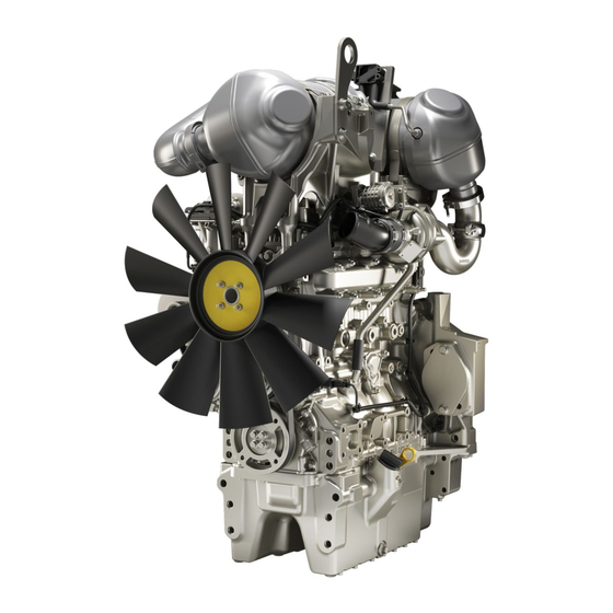
Model View Illustrations The following model views show typical features of the engine. Due to individual applications, your engine may appear different from the illustrations. 904J-E36TA Industrial Engine Views Illustration 22 g06297496 Typical example (1) Selective Catalytic Reduction (SCR) - Page 27 M0092609-05 Product Information Section Model View Illustrations Illustration 23 g06297569 Typical example (15) Front lifting eye (20) Electronic Control Module (ECM), (24) Coolant intake (16) Rear lifting eyes location for transportation only (25) Drive belt (17) Actuator for turbocharger (21) Idler for drive belt (26) Coolant outlet (18) Turbocharger (22) Adjuster for drive belt...
- Page 28 M0092609-05 Product Information Section Model View Illustrations 904J-E28T and 904J-E28TA Industrial Engine Views Illustration 24 g06481332 Typical example (1) Diesel Particulate Filter (DPF) and Diesel (4) Throttle control valve (8) Oil gauge (Dipstick) Oxidation Catalyst (DOC) combined (5) Alternator (9) Oil drain plug (2) Engine harness interface (6) Oil filter assembly (10) Starting motor...
- Page 29 M0092609-05 Product Information Section Model View Illustrations Illustration 25 g06481335 Typical example (12) Oil filler (upper) (17) Air intake from air cleaner (21) Coolant intake (13) Front lifting eye (18) Electronic Control Module (ECM), (22) Drive belt (14) Rear lifting eyes location for transportation only (23) Coolant outlet (15) Actuator for turbocharger...
- Page 30 M0092609-05 Product Information Section Model View Illustrations Loose or Off Engine Components Illustration 26 g06297651 Typical example (1) Primary fuel filter, combined with electric (4) Coolant diverter valve (10) Inlet temperature sensor fuel priming pump and Water-In-Fuel (5) Diesel Exhaust Fluid (DEF) pump with (11) Exhaust assembly (WIF) sensor DEF pump filter...
- Page 31 M0092609-05 Product Information Section Model View Illustrations 904J-E36TA Industrial Engine Views Illustration 27 g06511376 Typical example (1) Selective Catalytic Reduction (SCR) (5) Air intake from air charge cooler (9) Oil drain plug (1 of 2) (2) Diesel Exhaust Fluid (DEF) injector...
- Page 32 M0092609-05 Product Information Section Model View Illustrations Illustration 28 g06511390 Typical example (13) Rear lifting eyes (18) Oil filler (24) Fan pulley (14) Actuator for turbocharger (19) Oil drain plug (2 of 2) (25) Coolant outlet (15) Turbocharger (20) Automatic adjuster for drive belt (26) Air intake from air cleaner (16) Electronic Control Module (ECM), (21) Coolant pump pulley...
- Page 33 M0092609-05 Product Information Section Model View Illustrations Loose or Off Engine Components Illustration 29 g06297651 Typical example (1) Primary fuel filter, combined with electric (4) Coolant diverter valve (10) Inlet temperature sensor fuel priming pump and Water-In-Fuel (5) Diesel Exhaust Fluid (DEF) pump with (11) Exhaust assembly (WIF) sensor DEF pump filter...
- Page 34 Product Description i07943897 Product Description 904J-E36TA Industrial Engine The Perkins 904J-E36TA industrial engine is a single turbocharged, air to air charge cooled engine with an engine prefix of FW. The engine aftertreatment system is configured: • Diesel Oxidation Catalyst (DOC)
- Page 35 M0092609-05 Product Information Section Product Description There are three types of diagnostic codes: active, (Table 2, contd) logged, and event. Aspiration Turbocharged and Turbo- charged charge cooled Most of the diagnostic codes are logged and stored in the ECM. For additional information, refer to the Compression Ratio 17:1 Operation and Maintenance Manual, “Engine...
- Page 36 “Overhaul Considerations” topic (Maintenance Section). Aftermarket Products and Perkins Engines Perkins does not warrant the quality or performance of non-Perkins fluids and filters. When auxiliary devices, accessories, or consumables (filters, additives, catalysts) which are made by other manufacturers are used on Perkins products, the Perkins warranty is not affected simply because of such use.
-
Page 37: Product Identification Information
M0092609-05 Product Information Section Product Identification Information Product Identification Perkins dealers or Perkins distributors need all these numbers to determine the components that were Information included with the engine. This information permits accurate identification of replacement part numbers. The numbers for fuel setting information for electronic i07373047 engines are stored within the flash file. - Page 38 M0092609-05 Product Information Section Emissions Certification Film i07944182 Reference Information Information for the following items may be needed to order parts. Locate the information for your engine. Record the information in the appropriate space. Make a copy of this list for a record. Keep the information for future reference.
-
Page 39: Operation Section
There are several different designs of lifting eyes. The following sections give examples of lifting eyes on the engine, engine, and aftertreatment and factory installed radiator. Consult your Perkins distributor for information regarding fixtures for proper engine lifting. - Page 40 This action is for both safety and quality reasons. i07621581 Product Storage (Engine and Aftertreatment) Perkins are not responsible for damage which may occur when an engine is in storage after a period in service.
- Page 41 For maintenance procedures refer to this Operation The building must be kept at a constant temperature. and Maintenance Manual. Engines that are filled with Perkins ELC will have coolant protection to an ambient temperature of Monthly Checks −36° C (−32.8° F). The engine must not be subjected to extreme variations in temperature or humidity.
- Page 42 M0092609-05 Operation Section Engine and Aftertreatment Removal from Storage DEF has a limited life, refer to table 3 for the time and temperature range. DEF that is outside this range MUST be replaced. On removal from storage the DEF quality in the tank must be tested with a refractometer.
-
Page 43: Features And Controls
M0092609-05 Operation Section Features and Controls Features and Controls Intake manifold pressure – The intake manifold pressure sensor checks the rated pressure in the engine manifold. i07925952 Fuel rail pressure – The fuel rail pressure sensor Alarms and Shutoffs measures the high pressure or low pressure in the fuel rail. - Page 44 Determine and correct the cause of any significant change in the readings. Consult your Perkins dealer or your Perkins distributor for assistance. Some engine applications are equipped with Indicator Lamps.
- Page 45 3. Inspect the cooling system for leaks. If necessary, consult your Perkins dealer or your Perkins distributor for assistance.
- Page 46 M0092609-05 Operation Section Monitoring System The lamps will illuminate for 2 seconds to check that the lamps are functioning when the keyswitch is turned to the ON position. If any of the lamps stay illuminated, or a lamp fails to be illuminated the reason should be investigated immediately.
- Page 47 1. One or more of the shutdown values for diagnostic code. the engine protection strategy has been Contact your Perkins dealer or your Perkins exceeded. distributor. 2. A serious active diagnostic code has been detected.
- Page 48 DOC – Diesel Oxidation Catalyst DPF – Diesel Particulate Filter SCR – Selective Catalytic Reduction ECM – Electronic Control Module NOx – Nitrogen Oxides 904J-E36TA Industrial Engine Illustration 38 g06299856 Typical example (1) Engine 47-pin interface connector (5) Coolant temperature sensor...
- Page 49 M0092609-05 Operation Section Sensors and Electrical Components Illustration 39 g06299988 Typical example (12) Differential pressure sensor (15) Injector 3 and injector 4 (18) Engine oil pressure switch (13) NRS valve (16) Actuator for turbocharger (19) Fuel rail pressure sensor (14) Injector 1 and injector 2 (17) Crankshaft speed/timing sensor...
- Page 50 M0092609-05 Operation Section Sensors and Electrical Components Illustration 40 g06300327 Typical example (20) DEF Injector (22) Temperature sensor controller (A) DPF temperature probe (21) DPF Differential pressure sensor connection with 3 probes across (B) DOC temperature probe aftertreatment (C) SCR temperature probe...
- Page 51 M0092609-05 Operation Section Sensors and Electrical Components Illustration 41 g06511813 Industrial engine equipped with a balancer (23) DPF Differential pressure sensor (25) Temperature sensor controller (A) DOC temperature probe (24) DEF Injector connection with 3 probes across (B) DPF temperature probe aftertreatment (C) SCR temperature probe...
- Page 52 M0092609-05 Operation Section Sensors and Electrical Components 904J-E36TA Off Engine Sensors and Electrical Components Illustration 42 g06300407 Typical example (1) ECM (4) water in fuel switch (7) DEF pump (2) Air intake temperature sensor (Air (5) Coolant diverter valve (8) NOx sensors...
- Page 53 M0092609-05 Operation Section Sensors and Electrical Components 904J-E28T and 904J-E28TA Industrial Engines Illustration 43 g06481405 Typical example (1) Engine 47-pin interface connector (6) Starting motor (10) Inlet Manifold Temperature Sensor (2) Inlet throttle valve (7) Camshaft speed/timing sensor (11) Inlet Manifold Pressure Sensor (3) Temperature sensor pre-NRS valve (8) Fuel temperature sensor (12) Temperature sensor post NRS valve...
- Page 54 M0092609-05 Operation Section Sensors and Electrical Components Illustration 44 g06481410 Typical example (13) NRS Differential pressure sensor (15) Injector 1 and injector 2 (Injector 3 and (17) Engine oil pressure switch (14) NRS valve injector 4 not shown) (18) Fuel rail pressure sensor (16) Crankshaft speed/timing sensor...
- Page 55 M0092609-05 Operation Section Sensors and Electrical Components Illustration 45 g06481414 Typical example (19) Temperature sensor controller with 2 (20) Tube assembly for Differential pressure (A) DPF temperature probe probes across aftertreatment (in (21) DPF Differential pressure sensor (B) DOC temperature probe transport position) (22) Tube assembly for Differential pressure...
- Page 56 M0092609-05 Operation Section Sensors and Electrical Components 904J-E28T and 904J-E28TA Off Engine Sensors and Electrical Components Illustration 46 g06481423 Typical example (1) ECM (2) Air intake temperature sensor (Air (3) Priming pump Cleaner), If equipped (4) Water in fuel switch...
-
Page 57: Engine Diagnostics
The sequence of flashes represents the system diagnostic message. Count the first sequence of flashes in Perkins Electronic Engines have the capability to order to determine the first digit of the flash code. perform a self-diagnostics test. When the system... - Page 58 M0092609-05 Operation Section Engine Operation with Intermittent Diagnostic Codes Note: If the customer has selected “DERATE” and if there is a low oil pressure condition, the Electronic Control Module (ECM) will limit the engine power until the problem is corrected. If the oil pressure is within the normal range, the engine may be operated at the rated speed and load.
-
Page 59: Engine Starting
M0092609-05 Operation Section Engine Starting Engine Starting i08165229 Cold Weather Starting i08171598 Before Starting Engine Do not use aerosol types of starting aids such as Perform the required daily maintenance and other ether. Such use could result in an explosion and periodic maintenance before the engine is started. - Page 60 M0092609-05 Operation Section Starting the Engine 5. Repeat step 2 through step 4 if the engine fails to 3. When the warning light for the glow plugs is start. extinguished, turn the keyswitch to the START position to engage the electric starting motor and Note: After starting, the engine may be held at low crank the engine.
- Page 61 The batteries must be replaced or charged to the NOTICE proper voltage with a battery charger after the engine For 904J-E36TA industrial engine, ensure that a 12 is stopped. Many batteries which are considered VDC or 24 VDC battery source is used to start the en- unusable are still rechargeable.
- Page 62 M0092609-05 Operation Section After Starting Engine • Allow the engine to idle for 3 to 5 minutes, or allow the engine to idle until the water temperature indicator begins to rise. Check all gauges during the warm-up period. Constant speed engines should be allowed to operate at low idle for 3 minutes before used at operational speed.
-
Page 63: Engine Operation
Aftertreatment System emissions be reported to the end user. The exhaust gases and hydrocarbon particles from 904J-E36TA Industrial Engine the engine first pass through Diesel Oxidation Catalyst (DOC). Some of the gasses and matter are For engine model FW, 903.75 g/kWh was determined oxidized as the gasses pass through the DOC. - Page 64 EU type approval certificate. This CO The efficiency of the engine can affect the fuel measurement results from testing over a fixed test economy. Perkins design and technology in cycle, under laboratory conditions, with a parent manufacturing provides maximum fuel efficiency in engine representative of the engine family.
-
Page 65: Aftertreatment Operation
NOTICE Any warning should be investigated immediately. Allow at least 2 minutes after shutting down the en- Contact your Perkins dealer or your Perkins gine before you turn the battery disconnect switch to Distributor if further assistance is required. The OFF. - Page 66 M0092609-05 Operation Section Selective Catalytic Reduction Warning System • Inducement Categories The Inducements are • At Level 3 cycling the keyswitch will give 20 separated into categories. DEF Levels have minutes override at full power, before the inducement fault codes separate from the other shutdown or idle is triggered.
- Page 67 The stop lamp will be on solid Contact your Perkins dealer or your Perkins Distributor at level 1 warning, do not let the fault develop. Table 6 World-Wide Reduced Performance Setting Category 2 Fault (Non-Tampering Dosing and Interruption)
- Page 68 Emission malfunction lamp will be on solid lamp will flash lamp will flash lamp will flash The stop lamp will be on solid Contact your Perkins dealer or your Perkins Distributor at level 1 warning, do not let the fault develop.
- Page 69 The stop lamp will activate Contact your Perkins dealer or your Perkins Distributor at level 1 warning, do not let the fault develop. Table 9 World-Wide Reduced Time Setting Category 2 Fault (Non-Tampering Dosing Interruption)
- Page 70 The stop lamp will activate Contact your Perkins dealer or your Perkins Distributor at level 1 warning, do not let the fault develop. World-Wide DEF Level Warnings Two options are available but only one option will be enabled.
- Page 71 M0092609-05 Operation Section Selective Catalytic Reduction Warning System Table 12 World-Wide DEF Level Option 2 Normal operation Initial indication Level 1 Level 2 Level 3 Inducement Trigger Above 19 percent Below 19 percent Below 12.5 percent 6 Percent reading 0 Percent reading Inducement None None...
-
Page 72: Cold Weather Operation
Perkins Diesel Engines can operate effectively in start. cold weather. During cold weather, the starting and the operation of the diesel engine depends on the •... - Page 73 A block heater can be 120 V ac temperature is 80° C (176° F) minimum. Carbon 600W or 220 V ac 550W. Consult your Perkins dealer deposit on the valve stems will be kept at a minimum.
- Page 74 This return ensures that coolant flows around the engine Perkins recommends a warning device for the inlet under cold operating conditions. The water manifold temperature and/or the installation of an temperature regulator begins to open when the inlet air temperature gauge.
- Page 75 M0092609-05 Operation Section Fuel Related Components in Cold Weather Cold Filter Plugging Point (CFPP) is a temperature at Drain the water and sediment from any fuel storage which a particular fuel will pass through a tank at the following intervals: weekly, service standardized filtration device.
-
Page 76: Engine Stopping
M0092609-05 Operation Section Engine Stopping Engine Stopping Note: There may be regulations that define the requirements for the operator and/or support personnel to be present when the engine is running. i07693085 Stopping the Engine Leaving the machine unattended when the engine is running may result in personal injury or death. - Page 77 M0092609-05 Operation Section After Stopping Engine • Check the coolant for correct antifreeze protection and the correct corrosion protection. Add the correct coolant/water mixture, if necessary. Contact with high pressure fuel may cause fluid penetration and burn hazards. High pressure fuel •...
-
Page 78: Maintenance Section
M0092609-05 Maintenance Section Refill Capacities Maintenance Section Table 13 904J-E36TA Industrial Engine Refill Capacities Refill Capacities Compartment or System Capacity 8 to 10.6 L Crankcase Oil Sump i08024095 (2.11360 to 2.80052 US gal) Refill Capacities These values are the approximate capacities for the crankcase oil sump which includes the standard factory installed oil filters. - Page 79 Table 18 Table 15 DEF Tank Capacity 904J-E36TA Industrial Engine With a Balancer Oil Pan 19 L (5 US gal) Refill Capacities OEM tank size shape, and capacities could be different. Compartment or System...
- Page 80 To meet the “EMA Recommended Guideline on Diesel Engine designed life of the product, the use of the Oil”. In addition to Perkins definitions, there are other definitions that will be of assistance in purchasing appropriate engine oil is essential. The oil lubricants.
- Page 81 This analysis allows technicians to determine the amount of Perkins does not recommend the use of aftermarket deterioration of the oil during use. This analysis additives in oil. The use of aftermarket additives is...
- Page 82 M0092609-05 Maintenance Section General Fuel Information • CFR Co-ordinating Fuel Research NOTICE The footnotes are key part of the Perkins "Specifica- • ULSD Ultra Low Sulfur Diesel tion for Distillate Diesel Fuel" Table. Read ALL of the footnotes. • RME Rape Methyl Ester •...
- Page 83 M0092609-05 Maintenance Section General Fuel Information Table 20 "Perkins Specification for Distillate Diesel Fuel" Property UNITS Requirements “ASTM”Test “ISO/Other”Test Aromatics %Volume 35% maximum “D1319” “ISO 3837” %Weight 0.01% maximum “D482” “ISO 6245” Carbon Residue on 10% %Weight 0.20% maximum “D524”...
- Page 84 EPA and other appropriate regulatory agencies. NOTICE Operating with fuels that do not meet the Perkins rec- ommendations can cause the following effects: Start- ing difficulty, reduced fuel filter service life, poor combustion, deposits in the fuel injectors, signifi- cantly reduce service life of the fuel system.
- Page 85 “Operation and Maintenance Manual” Fluid Recommendations for EN16709 B20 specification - Europe more information. All the fuels must comply with the specification in the table for the Perkins Specification Distillate Diesel Fuel. Diesel Fuel Characteristics Perkins recommends kinematic viscosities of 1.4 and 4.5 mm2/sec that is delivered to the fuel injection...
- Page 86 Protection Agency (EPA) and European Certification wear scar diameter than 0.52 mm (0.0205 inch) will fuels. Perkins does not certify engines on any other lead to reduced service life and premature failure of fuel. The user of the engine has the responsibility of the fuel system.
- Page 87 20 hours or more as per EN 15751. If the test shows that the fuel has • Perkins recommend the use of oil analysis to degraded, fuel tank must be drained and engine check the quality of the engine oil if biodiesel fuel flushed by running with the fresh high-quality diesel fuel.
- Page 88 “Operation and Maintenance Manual” Fluid Recommendations If biodiesel or biodiesel blends of fuel are to be used, Perkins require the use of Perkins fuel cleaner. The Fuel for Cold-Weather Operation use of the fuel is to remove deposits within the fuel system that is created with the use of biodiesel.
- Page 89 Note: Perkins fuel cleaner is compatible with existing water or less. and U.S. EPA Tier 4 nonroad certified diesel engine • Perkins recommends the use of bulk fuel filter / emission control catalysts and particulate filters. coalescer units which clean the fuel of both...
- Page 90 Specification water. Caution should be used when dispensing DEF near an engine that has recently been running. DEF that is used in Perkins engines must meet the Spilling DEF onto hot components will cause harmful vapors. ISO specification 22241-1 for quality. The ISO...
- Page 91 M0092609-05 Maintenance Section Fluid Recommendations • Chromium Nickel Molybdenum (CrNiMo) NOTICE Never operate an engine without water temperature • Titanium regulators in the cooling system. Water temperature regulators help to maintain the engine coolant at the Non-metallic materials: proper operating temperature. Cooling system prob- lems develop without water...
- Page 92 • Cavitation of the water pump relies on organic inhibitors for corrosion and cavitation protection. Also known as Organic Acid For optimum performance, Perkins recommends a Technology (OAT) coolant. 50 percent by volume of glycol in the finished coolant (also referred to as 1:1 mixture).
- Page 93 ELC is an ethylene glycol base coolant. However, ELC contains organic corrosion inhibitors and antifoam agents with low amounts of nitrite. Perkins ELC has NOTICE been formulated with the correct amount of these A commercial heavy-duty antifreeze that meets additives to provide superior corrosion protection for “ASTM D4985”...
- Page 94 8. Repeat Steps 6 and repeat steps 7 until the To change from heavy-duty antifreeze to the Perkins system is completely clean. ELC, perform the following steps: 9. Fill the cooling system with the Perkins Premixed ELC. NOTICE Care must be taken to ensure that all fluids are con-...
- Page 95 Coolants that conform to “ASTM D4985” and do not regulations. Flush the system with a 5 to 10 conform to “ASTM D6210” will require addition of percent solution of Perkins ELC. Fill the system SCA at initial fill. with the Perkins ELC.
- Page 96 3. Dissolve a suitable cleaning agent in water: use non-foaming detergent to clean oil contamination or a cooling system cleaner to clean deposits. Consult your Perkins dealer for suitable product. 4. Run the engine for approximately 30 minutes, leave the engine to cool down, and drain the...
-
Page 97: Maintenance Recommendations
Consult the OEM of the equip- To relieve the pressure from the coolant system, turn ment or your Perkins dealer regarding welding on a chassis frame or rail. off the engine. Allow the cooling system pressure cap to cool. - Page 98 M0092609-05 Maintenance Section Welding on Engines with Electronic Controls 1. Stop the engine. Turn the switched power to the OFF position. 2. Ensure that the fuel supply to the engine is turned off. 3. Disconnect the negative battery cable from the battery.
- Page 99 • Failure to use recommended fuel, lubricants, and Refer to the standards for the engine or consult your coolant/antifreeze Perkins distributor to determine if the engine is operating within the defined parameters. Severe service operation can accelerate component wear. Engines that operate under severe conditions...
-
Page 100: Maintenance Interval Schedule
M0092609-05 Maintenance Section Maintenance Interval Schedule “ Fuel System Secondary Filter - Replace“..129 i08187495 Maintenance Interval Schedule Every 1000 Service Hours “ Belt - Inspect“ ......103 “... -
Page 101: Battery - Replace
Aftercooler Core - Clean/Test Alternator - Inspect (Air-To-Air Aftercooler) Perkins recommends a scheduled inspection of the alternator. Inspect the alternator for loose The air-to-air aftercooler is OEM installed in many connections and correct battery charging. Check the applications. Please refer to the OEM specifications ammeter (if equipped) during engine operation in for information that is related to the aftercooler. -
Page 102: Battery Or Battery Cable - Disconnect
M0092609-05 Maintenance Section Battery Electrolyte Level - Check The battery cables or the batteries should not be All lead-acid batteries contain sulfuric acid which can burn the skin and clothing. Always wear a removed with the battery cover in place. The bat- face shield and protective clothing when working tery cover should be removed before any servic- on or near batteries. -
Page 103: Belt - Inspect
M0092609-05 Maintenance Section Belt - Inspect 2. Disconnect the negative battery terminal. Ensure • Inspect the belt for cracks, splits, glazing, grease, displacement of the cord and evidence of fluid that the cable cannot contact the terminal. When contamination. four 12 V batteries are involved, 2 negative connections must be disconnected. -
Page 104: Coolant (Commercial Heavy-Duty) - Change
M0092609-05 Maintenance Section Coolant (Commercial Heavy-Duty) - Change • The fuel has entered the cooling system and the coolant is contaminated. NOTICE When any servicing or repair of the engine cooling system is performed, the procedure must be per- formed with the engine on level ground. Level ground will allow you to check accurately the coolant level. - Page 105 This operation will suitable cleaning agent to remove any debris. allow any air in the system to be purged. Decrease Refer to your Perkins dealer or distributor for the engine speed to low idle. Stop the engine. suitable cleaning agents.
-
Page 106: Coolant (Commercial Heavy-Duty) - Change
To open the cooling system filler cap, suitable cleaning agent to remove any debris. stop the engine and wait until the cooling system Refer to your Perkins dealer or distributor for components are cool. Loosen the cooling system suitable cleaning agents. -
Page 107: Coolant (Elc) - Change
M0092609-05 Maintenance Section Coolant (ELC) - Change 3. Fill the cooling system with clean water and install 4. Clean the cooling system filler cap. Inspect the the cooling system filler cap. gasket that is on the cooling system filler cap. If the gasket that is on the cooling system filler cap is 4. - Page 108 2. Start and run the engine at low idle. Increase the engine rpm to high idle. Operate the engine to For information regarding the disposal and the recycling of used coolant, consult your Perkins dealer open the engine thermostat. An open thermostat or Perkins distributor.
-
Page 109: Def Filler Screen (Emission Related Component) - Clean
M0092609-05 Maintenance Section Coolant Level - Check 4. Clean the cooling system filler cap. Inspect the gasket that is on the cooling system filler cap. If the gasket that is on the cooling system filler cap is damaged, discard the old cooling system filler cap and install a new cooling system filler cap. -
Page 110: Def Manifold Filters (Emission Related Component) - Replace
M0092609-05 Maintenance Section DEF Manifold Filters (Emission Related Component) - Replace i07383199 DEF Manifold Filters (Emission Related Component) - Replace Illustration 62 g03725939 Illustration 63 g06302888 Typical example Typical example 1. Ensure that the area around cap on the Diesel 1. -
Page 111: Diesel Exhaust Fluid (Emission Related Component) - Fill
M0092609-05 Maintenance Section Diesel Exhaust Fluid (Emission Related Component) - Fill 1. Before filling the DEF tank, ensure that the DEF i07383319 lines have been purged. Purging of the DEF lines Diesel Exhaust Fluid will take place, after the engine has stopped. Only (Emission Related after the DEF lines have purged, should the DEF tank be filled. -
Page 112: Diesel Exhaust Fluid Filter (Emission Related Component) - Replace
M0092609-05 Maintenance Section Diesel Exhaust Fluid Filter (Emission Related Component) - Replace 1. Ensure that the area around the DEF filter is clean i07383609 and free from dirt. Use a 27mm Bi-Hex socket to Diesel Exhaust Fluid Filter remove filter cap (4). (Emission Related 2. -
Page 113: Diesel Exhaust Fluid Tank - Flush
M0092609-05 Maintenance Section Diesel Exhaust Fluid Injector (Emission Related Component) - Replace i07385681 i07383720 Diesel Exhaust Fluid Injector Diesel Exhaust Fluid Tank - (Emission Related Flush Component) - Replace Required Tools Table 31 Required Tools Part Description Tool Part Number Plugs Flushing Procedure 1. - Page 114 M0092609-05 Maintenance Section Diesel Exhaust Fluid Tank - Flush Illustration 69 g06357825 Typical example (2) Manifold (DEF heater) (7) Filter 5. Remove the filter from the manifold (DEF heater). Refer to Disassembly and Assembly, “Manifold Illustration 68 g03708638 (DEF Heater) - Remove and Install” for the correct Typical example procedure.
-
Page 115: Engine - Clean
M0092609-05 Maintenance Section Driven Equipment - Check 15. Perform the “Aftertreatment System Functional Test” in the electronic service tool. This test will verify that the DEF system is working correctly following the flush and filter replacement. i02151646 Driven Equipment - Check Refer to the OEM specifications for more information on the following maintenance recommendations for the driven equipment:... -
Page 116: Engine Air Cleaner Element - Replace
Servicing the Air Cleaner Elements Note: The air filter system may not have been provided by Perkins. The procedure that follows, is for a typical air filter system. Refer to the OEM information for the correct procedure. -
Page 117: Engine Air Cleaner Service Indicator - Inspect
M0092609-05 Maintenance Section Engine Air Cleaner Service Indicator - Inspect 2. Inspect the top cover (1) and if necessary remove top cover to clean cover. Ensure that dirt cannot enter the air cleaner system with top cover removed. If necessary, clean top cover and install. 3. -
Page 118: Engine Air Precleaner - Check/Clean
Refer to the OEM information for the recommended torques. i07819526 When the engine mounts are supplied by Perkins the maintenance procedure will be supplied in the Engine Air Precleaner - Check/ Disassembly and Assembly manual for your engine. -
Page 119: Engine Oil Sample - Obtain
The condition of the engine lubricating oil may be checked at regular intervals as part of a preventive maintenance program. Perkins include an oil sampling valve as an option. The oil sampling valve (if equipped) is included in order to regularly sample the engine lubricating oil. -
Page 120: Engine Oil And Filter - Change
M0092609-05 Maintenance Section Engine Oil and Filter - Change Perkins recommends using a sampling valve in order The sample can be checked for the following: the to obtain oil samples. The quality and the consistency quality of the oil, the existence of any coolant in the... - Page 121 24 N·m (212 lb in). If the engine is operated in severe service conditions, Draining the Engine Lubricating Oil Perkins recommends the use of engine oil sampling. Refer to this Operation and Maintenance Manual, From an Oil Pan Equipped With a Engine Oil sample - Obtain for more information.
- Page 122 M0092609-05 Maintenance Section Engine Oil and Filter - Change Illustration 79 g06511911 Typical example of an engine oil pan with a balancer 1. Place a suitable container below oil drain plug (1) and oil drain plug (5). 2. Remove oil drain plug (1) and oil drain plug (5) from engine oil pan (3) and allow the oil to drain into the container for storage or disposal.
- Page 123 M0092609-05 Maintenance Section Engine Oil and Filter - Change 5. Tighten oil drain plug (1) and oil drain plug (5) to a 5. Tighten cap (1) to a torque of 24 N·m (212 lb in) torque of 24 N·m (212 lb in). Remove container Fill the Oil Pan below oil drain plug (1) and oil drain plug (5).
- Page 124 M0092609-05 Maintenance Section Fuel System - Prime Electric Fuel Priming Pump 2. Fill the oil pan with the correct amount of new engine lubricating oil. Refer to this Operation and Use the following procedure to remove air from the Maintenance Manual, “Refill Capacities” for more fuel system: information on refill capacities.
-
Page 125: Fuel System Primary Filter (Water Separator) Element - Replace
M0092609-05 Maintenance Section Fuel System Primary Filter (Water Separator) Element - Replace Note: As the fuel system is primed, the pressure will NOTICE increase within the fuel system and this increase in Ensure that the engine is stopped before any servic- pressure can be felt during priming. - Page 126 M0092609-05 Maintenance Section Fuel System Primary Filter (Water Separator) Element - Replace Install the New Filter Element Note: If a strap wrench is required to loosen the filter bowl (5), ensure that the strap is positioned in the middle of the ribbed section. To avoid damage or mechanical failure, do not position the strap around the clear area.
- Page 127 M0092609-05 Maintenance Section Fuel System Primary Filter (Water Separator) Element - Replace 6. The secondary filter element (if equipped) must be Note: If a strap wrench is required to loosen the filter bowl (5), ensure that the strap is positioned in the replaced at the same time as the primary filter middle of the ribbed section.
- Page 128 M0092609-05 Maintenance Section Fuel System Primary Filter/Water Separator - Drain Install the New Filter Element 6. The secondary filter element (if equipped) must be replaced at the same time as the primary filter element. Refer to the Operation and Maintenance Manual, “Fuel System Secondary Filter - Replace”.
-
Page 129: Fuel System Secondary Filter - Replace
M0092609-05 Maintenance Section Fuel System Secondary Filter - Replace Remove the Element 1. Turn the fuel supply valve (if equipped) to the OFF position before performing this maintenance. 2. Place a suitable container under the fuel filter to catch any fuel that might spill. Clean up any spilled fuel. -
Page 130: Fuel Tank Water And Sediment - Drain
M0092609-05 Maintenance Section Fuel Tank Water and Sediment - Drain 3. Do not use a tool to install the filter assembly. Tighten the assembly by hand. Install the filter bowl (2). Turn the filter bowl clockwise until the filter bowl locks into position against the stops. 4. -
Page 131: Hoses And Clamps - Inspect/Replace
M0092609-05 Maintenance Section Hoses and Clamps - Inspect/Replace Check the fuel daily. Allow five minutes after the fuel • Cracking tank has been filled before draining water and • Softness sediment from the fuel tank. Fill the fuel tank after operating the engine in order to •... -
Page 132: Starting Motor - Inspect
Refer to the Systems Operation, Testing and Adjusting Manual, “Electric Starting System - Test” for more information on the checking procedure and for specifications consult your Perkins dealer or your Perkins distributor for assistance. Illustration 93 g06304904... - Page 133 M0092609-05 Maintenance Section Walk-Around Inspection 1. Ensure that the turbocharger is clean and free from NOTICE dirt before removing components for inspection. For any type of leak (coolant, lube, or fuel) clean up the fluid. If leaking is observed, find the source and 2.
-
Page 134: Water Pump - Inspect
M0092609-05 Maintenance Section Water Pump - Inspect Engine Aftertreatment After the engine has stopped, wait 10 minutes to allow the fuel pressure to be purged from the high- pressure fuel lines before any service or repair is Check the condition of the coolant lines, Diesel performed. -
Page 135: Warranty Section
Emissions Warranty. For a full warranty statement contact your Perkins dealer or your Perkins distributor. For customers that have a valid user name and password, for perkins. com. Login then go to TIPSS, and the warranty information can be accessed. -
Page 136: Reference Information Section
M0092609-05 Reference Information Section Reference Materials Reference Information Section Reference Materials i05204675 Maintenance Log Table 32 Engine Model Customer Identifier Arrangement Number Serial Number Service Quantity Of Service Item Date Authorization Hours Fuel (continued) - Page 137 Contact your local Perkins Distributor Reference Material now and the distributor can provide you with a quote in minutes. You can locate your nearest Perkins (Extended Service Contract) Distributor by visiting: www.perkins.com Extended Service Contracts - purchased in minutes, NOTICE protected for years.
-
Page 138: Index
M0092609-05 Index Section Index Flush ............108 Coolant Level - Check ........109 Additional Messages ........12 Crushing Prevention and Cutting Prevention.. 20 After Starting Engine ........61 After Stopping Engine ........76 Aftercooler Core - Clean/Test (Air-To-Air Aftercooler) ..........101 DEF Filler Screen (Emission Related Aftercooler Core - Inspect ...... - Page 139 M0092609-05 Index Section Oil and Filter Change Intervals ....120 Fuel Related Components in Cold Weather ... 75 Replace the Oil Filter Element....123 Fuel Filters ........... 75 Engine Oil Level - Check........118 Fuel Heaters ..........75 After Operating the Engine ......119 Fuel Tanks ...........
- Page 140 904J-E28T and 904J-E28TA Industrial Engine DEF System..........79 Views............28 Lubrication System for Engines Equipped 904J-E36TA Industrial Engine Views ..26, 31 With a Balancer Oil Pan......78 Loose or Off Engine Components ..30, 33 Lubrication System for Engines Equipped Monitoring System (Engine Indicators and With a Standard Oil Pan ......
- Page 141 M0092609-05 Index Section 904J-E28T and 904J-E28TA Industrial Engines ............53 904J-E36TA Industrial Engine..... 48 Severe Service Application ......99 Environmental Factors......... 99 Incorrect Maintenance Procedures ..... 99 Incorrect Operating Procedures ....99 Starting Motor - Inspect ......... 132 Starting the Engine.......... 60 Starting the Engine ........
- Page 143 Product and Dealer Information Note: For product identification plate locations, see the section “Product Identification Information” in the Operation and Maintenance Manual. Delivery Date: Product Information Model: Product Identification Number: Engine Serial Number: Transmission Serial Number: Generator Serial Number: Attachment Serial Numbers: Attachment Information: Customer Equipment Number: Dealer Equipment Number:...
- Page 144 M0092609 ©2021 Perkins Engines Company Limited All Rights Reserved January 2021...