Sign In
Upload
Download
Table of Contents
Contents
Add to my manuals
Delete from my manuals
Share
URL of this page:
HTML Link:
Bookmark this page
Add
Manual will be automatically added to "My Manuals"
Print this page
×
Bookmark added
×
Added to my manuals
Manuals
Brands
Perkins Manuals
Engine
4006
User handbook manual
Perkins 4006 User Handbook Manual
Diesel engine
Hide thumbs
1
2
3
4
Table Of Contents
5
6
7
8
9
10
11
12
13
14
15
16
17
18
19
20
21
22
23
24
25
26
27
28
29
30
31
32
33
34
35
36
37
38
39
40
41
42
43
44
45
46
47
48
49
50
51
52
53
54
55
56
57
58
59
page
of
59
Go
/
59
Contents
Table of Contents
Bookmarks
Table of Contents
Table of Contents
Brief Description of the 4006/8 Diesel Engines
General Information
Diesel Engine Data
Torque Settings
Lubricating Oil Recommendations
Fuel Specification
Operating Instructions
Preparation for Initial Start
Batteries
Priming the Lubrication System
Filling Cooling System
Priming the Fuel System
Instrument Panel (Engine Mounted)
Exhaust Temperature Gauge (Engine Mounted)
Normal Starting Procedure
Engine Shutdown
Light Load Operation and Standby Generating Sets
Maintenance Procedures
Fault Tracing Chart
Wiring Diagram Cav Starter, with Repeater Relay
Wiring Diagram Cav Starter, Without Repeater Relay
Wiring Diagram Cav Starter with Repeater Relay
Wiring Diagram Engine Without Repeater (Manual Start)
Wiring Diagram Prestolite Starter with Repeater Relay
Wiring Diagram Prestolite Starter Without Repeater Relay
Advertisement
Quick Links
1
Brief Description of the 4006/8 Diesel Engines
2
Diesel Engine Data
3
Torque Settings
4
Fuel Specification
5
Maintenance Procedures
6
Wiring Diagram Cav Starter, with Repeater Relay
Download this manual
TSL4184E
May 1998
User's
Handbook
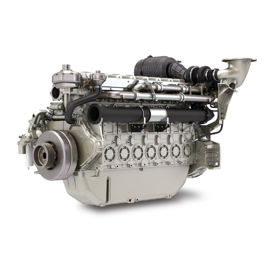
Perkins 4006 and 4008 Diesel
4006
4008
Table of
Contents
Previous
Page
Next
Page
1
2
3
4
5
Advertisement
Table of Contents
Need help?
Do you have a question about the 4006 and is the answer not in the manual?
Ask a question
Questions and answers
Related Manuals for Perkins 4006
Engine Perkins 4006-23TAG1A User Handbook Manual
4000 series inline diesel engine (46 pages)
Engine Perkins 4006-23TAG2A User Handbook Manual
4000 series inline diesel engine (46 pages)
Engine Perkins 4006-23TAG3A User Handbook Manual
4000 series inline diesel engine (46 pages)
Engine Perkins 4008 User Handbook Manual
Diesel engine (59 pages)
Engine Perkins 400 Series Operation And Maintenance Manual
Industrial engine (80 pages)
Engine Perkins 400 Series Operation And Maintenance Manual
Industrial engines (100 pages)
Engine Perkins 400 Series Operation And Maintenance Manual
Industrial engine (88 pages)
Engine Perkins 400 Series User Handbook Manual
4000 series diesel engine (76 pages)
Engine Perkins 4006D-E23TA Operation And Maintenance Manual
Industrial engines (88 pages)
Engine Perkins 4006-23 Operation And Maintenance Manual
Industrial engines (88 pages)
Engine Perkins 4008-30 Operation And Maintenance Manual
Industrial engines (102 pages)
Engine Perkins 4008-30 SD8 Systems Operation, Testing And Adjustment
Industrial engine (42 pages)
Engine Perkins 400A Series Operation And Maintenance Manual
Industrial engines (100 pages)
Engine Perkins 400D Series Operation And Maintenance Manual
Industrial engines (100 pages)
Engine Perkins 400C Operation And Maintenance Manual
Industrial engine (88 pages)
Engine Perkins 4006 TRS Gas Operation And Maintenance Manual
(90 pages)
This manual is also suitable for:
4008
Table of Contents
Save PDF
Print
Rename the bookmark
Delete bookmark?
Delete from my manuals?
Login
Sign In
OR
Sign in with Facebook
Sign in with Google
Upload manual
Upload from disk
Upload from URL


Need help?
Do you have a question about the 4006 and is the answer not in the manual?
Questions and answers