Table of Contents
Advertisement
Advertisement
Table of Contents

Related Manuals for Perkins M92B


Summary of Contents for Perkins M92B
- Page 1 Part No N37347 ® User’s Handbook M92B...
- Page 3 © Proprietary information of Wimborne Marine Power Centre, all rights reserved. The information is correct at the time of print. Published in December 2013 by Wimborne Marine Power Centre, Wimborne, Dorset, England BH21 7PW Tel: +44(0)1202 796000 Fax: +44(0)1202 796001 E -mail: Marine@Perkins.com www.perkins.com/Marine...
- Page 4 Title N37347...
-
Page 5: Table Of Contents
Introduction ........................1 How to care for your engine ..................2 General safety precautions ..................4 Engine guarantee ......................5 Perkins companies .......................6 2 Engine views .....................9 Introduction ........................9 Front and left side view (A) of the engine ............9 Rear and right side view (B) of the engine .............10 3 Operation instructions ................ - Page 6 Contents N37347 How to check the specific gravity of the coolant .............23 How to drain the raw water system ................24 How to check the impeller of the raw water pump ...........25 How to check the drive belt ..................26 How to adjust the belt tension ................26 How to renew the element of the fuel filter ...............27 Fuel pre-filter ....................27 Atomiser maintenance ....................28...
- Page 7 N37347 Contents POWERPART recommended consumable products ..........51 9 General data .....................53 Engine .......................53 Reverse gearbox ....................53...
- Page 8 Contents N37347...
-
Page 9: General Information
Chapter 1 General information Introduction The Perkins M92B marine engine is the latest development from Perkins Engines Company Limited together with Wimborne Marine Power Centre. The engine is designed specifically for use in commercial and pleasure boat applications. Over sixty years of diesel production experience, together with the latest technology, have been applied to the manufacture of your engine to give you reliable and economic power. -
Page 10: How To Care For Your Engine
Ensure that all adjustments and repairs are done by personnel who have had the correct training. Perkins distributors have this type of personnel available. You can also obtain parts and service from your Perkins distributor. - Page 11 N37347 Chapter 1 Page 3...
-
Page 12: General Safety Precautions
• Do not clean an engine while it runs. If cold cleaning fluids are applied to a hot engine, certain components on the engine may be damaged. • Fit only genuine Perkins parts. Page 4... -
Page 13: Engine Guarantee
Chapter 1 Engine guarantee If a claim under guarantee is necessary, the boat owner should make a guarantee claim on the nearest Perkins marine distributor or an approved dealer. If it is difficult to find a Perkins distributor or an approved dealer, consult the Service Department of Wimborne Marine Power Centre, Wimborne. -
Page 14: Perkins Companies
2-2-19 Akasaka, Minato-ku, Tokyo 107-0052, Japan. Telephone: 0081 (0) 3 3560 3878 Fax: 0081 (0) 3 3560 3877 Singapore Perkins Engines (Asia Pacific) pte Ltd 20 Harbour Drive #07-06A, PSA Vista Singapore 117612 Telephone: (65) 874 7712 Fax: (65) 874 7722... - Page 15 Telex: 32501 Perken G Fax: 001 305 442 7419 In addition to the above companies, there are Perkins distributors in most countries. Perkins Engines Company Ltd., Peterborough or one of the above companies can provide details. The managers of the marine business for Perkins are:...
- Page 16 Chapter 1 N37347 Page 8...
-
Page 17: Engine Views
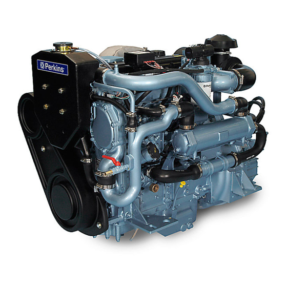
N37347 Chapter 2 Engine views Introduction Perkins engines are built for specific applications and the views that follow do not necessarily match your engine’s specification. Location of engine parts Front and left side view (A) of the engine Air cleaner... -
Page 18: Rear And Right Side View (B) Of The Engine
Chapter 2 N37347 Rear and right side view (B) of the engine 17. Front lifting eye 18. Calorifier fitting (feed) 19. Alternator 20. Exhaust elbow 21. Oil filter 22. Starter 23. Lubricating oil sump 24. Sump pump 25. Exhaust manifold 26. -
Page 19: Operation Instructions
N37347 Chapter 3 Operation instructions How to start the engine The instrument control panel for single and twin engine installations is shown in figure (A). The switches are protected from the entry of water, but if the control panel is in an exposed location, it should be protected by a cover when not in use. -
Page 20: Basic Control Panel
Chapter 3 N37347 Basic control panel The basic control panel shown in figure (B). The switches are protected from the entry of water, but if the control panel is in an exposed location, it should be protected by a cover when not in use. Below is a description of the instrument and switches on the auxiliary panel. -
Page 21: Engine Wiring Harness
N37347 Chapter 3 Engine Wiring Harness, The engine wiring harness is designed convey information to and from the engine instrument / control panel. Within the harness is a circuit breaker and a –ve earth fuse to protect the wiring in the event of a short circuit as well as control relays, all of which are housed in an enclosure adjacent to the alternator. -
Page 22: How To Start The Engine
Chapter 3 N37347 How to start the engine Use only this procedure to start the engine; it has been designed to protect the engine and the environment. Several factors affect engine start, for example: • The power of the batteries •... -
Page 23: How To Stop The Engine
The idle or maximum speed settings must not be changed by the engine operator, because this can damage the engine or the transmission. The warranty of the engine can be affected if the seals on the fuel injection pump are broken during the warranty period by a person who is not approved by Perkins. Running-in A gradual running-in of a new engine is not necessary. -
Page 24: Free Rotation Of The Propeller Shaft Or "Trailing
Chapter 3 N37347 Free rotation of the propeller shaft or “trailing” The propeller shaft of both the Newage PRM 500D and the Hurth 45 A reverse gearboxes can be allowed to turn continuously with the control lever in the neutral position. The recommendations of the manufacturer of the reverse gearbox must be followed. -
Page 25: Emergency Procedures
N37347 Chapter 3 Emergency procedures If the engine stops Check that the fuel supply valve (if fitted) is in the open position. Check the fuel pre-filter (if fitted) and the fuel filters for water. If a warning light for water in the fuel is fitted, and it is illuminated, water has entered the pre-filter. - Page 26 Chapter 3 N37347 Page 18...
-
Page 27: Preventive Maintenance
N37347 Chapter 4 Preventive maintenance Preventive maintenance periods These preventive maintenance periods apply to average conditions of operation. Check the periods given by the manufacturer of the boat in which the engine is installed. If necessary, use the shorter periods. When the operation of the engine must conform to the local regulations these periods and procedures may need to be adapted to ensure correct operation of the engine. -
Page 28: Schedules
Chapter 4 N37347 Schedules The schedules which follow must be applied at the interval (hours or months) which occur first. A First service at 25/50 hours D Every 500 hours or 12 months G Non-scheduled maintenance B Every day or every 8 hours E Every 1000 hours C Every 250 hours or 12 months F Every 2000 hours... -
Page 29: How To Fill The Coolant Circuit
N37347 Chapter 4 How to fill the coolant circuit Warning! If coolant is to be added to the circuit during service, allow the engine to cool before the coolant is added. Remove the filler cap slowly as dangerous coolant could be discharged if the coolant is still hot and the system is under pressure. -
Page 30: How To Drain The Coolant Circuit
Chapter 4 N37347 How to drain the coolant circuit Warnings! • Do not drain the coolant while the engine is still hot and the system is under pressure because dangerous hot coolant can be discharged. • Discard used coolant in a safe place and in accordance with local regulations. Remove the filler cap of the coolant circuit. -
Page 31: How To Check The Specific Gravity Of The Coolant
N37347 Chapter 4 How to check the specific gravity of the coolant For mixtures which contain inhibited ethylene glycol: Operate the engine until it is warm enough to open the thermostat. Continue to run the engine until the coolant has circulated the cooling system. Stop the engine. -
Page 32: How To Drain The Raw Water System
Chapter 4 N37347 How to drain the raw water system Caution: The raw water system cannot be drained completely. If the system is drained for engine preservation purposes or for protection from frost, the system must be filled again with an approved antifreeze mixture. See “Coolant specification”... -
Page 33: How To Check The Impeller Of The Raw Water Pump
N37347 Chapter 4 How to check the impeller of the raw water pump Ensure that the seacock is closed. Release the six setscrews which fasten the end plate of the raw water pump and remove the plate. When the end plate of the raw water pump is removed, some raw water will flow from the pump. Remove the rubber end cap (H1) and then pull the impeller from the shaft. -
Page 34: How To Check The Drive Belt
- 45N (10 lbf) 4,5 kgf - the correct deflection of the belt is 10 mm (3/8 in). How to adjust the belt tension The alternator is driven by a drive belt of a specific design. Use only a Perkins POWERPART drive belt. If this is not done, an early failure of the belt may occur. -
Page 35: How To Renew The Element Of The Fuel Filter
Warning! Discard the used canister and fuel oil in a safe place and in accordance with local regulations. Caution: It is important that only the genuine Perkins parts are used. The use of wrong parts could damage the fuel injection equipment. -
Page 36: Atomiser Maintenance
Chapter 4 N37347 Atomiser maintenance Caution: A faulty atomiser must be renewed by a person who has had the correct training. Atomiser faults Caution: A faulty atomiser must be renewed by a person who has had the correct training. Regular maintenance of the atomisers is not necessary. The atomiser nozzles should be renewed and not cleaned, and renewed only if an atomiser fault occurs. -
Page 37: How To Remove And To Fit An Atomiser
N37347 Chapter 4 How to remove and to fit an atomiser How to remove Warning! The combustible material of some components of the engine (for example certain seals) can become extremely dangerous if it is burned. Never allow this burnt material to come into contact with the skin or with the eyes. -
Page 38: How To Fit
Chapter 4 N37347 How to fit Remove all covers and caps from the component and connections. Put a new seat washer into the seat recess in the cylinder head. Note: Some new atomiser’s have the seat washer (P3) fitted on the atomiser. Ensure that the atomiser seal (P2) is not damaged. -
Page 39: How To Eliminate Air From The Fuel System
N37347 Chapter 4 How to eliminate air from the fuel system Cautions: • Under no circumstances should any attempt be made to remove the electric fuel lift pump from the filter head as it is not a serviceable item. • Do not operate the engine until the air is eliminated from the fuel injection pump. •... -
Page 40: How To Renew The Lubricating Oil
Chapter 4 N37347 How to renew the lubricating oil Warning! Discard the used lubricating oil in a safe place and in accordance with local regulations. Note: Renew the filter canister when the lubricating oil is renewed. Using the sump drain pump (S1). Pump the lubricating oil into a suitable container with a capacity of approximately 10 litres (17.5 pints), the lubricating oil should be drained while it is still hot. -
Page 41: How To Renew The Canister Of The Lubricating Oil Filter
Do not fill the sump past the notch on the dipstick. Cautions: • The canister contains a valve and special tube to ensure that lubricating oil does not drain from the filter. • Therefore, ensure that the correct Perkins POWERPART canister is used. Page 33... -
Page 42: How To Renew The Lubricating Oil Of The Newage Prm 500D Reverse Gearbox
Chapter 4 N37347 How to renew the lubricating oil of the Newage PRM 500D reverse gearbox Caution: In service the lubricating oil of these reverse gearboxes should be checked with the lubricating oil cold. Always check the lubricating oil level before the transmission is used. Put a suitable container with a capacity of at least 3 litres (5 pints) under the reverse gearbox. -
Page 43: How To Renew The Lubricating Oil Of The Zf 45 A Reverse Gearbox
N37347 Chapter 4 How to renew the lubricating oil of the ZF 45 A reverse gearbox Note: When the lubricating oil of the reverse gearbox is renewed, the filter element should also be renewed. Turn the filler cap (W1) counter-clockwise with a 6 mm Allen Key (W2) and remove the cap together with the filter that is fitted to the cap. -
Page 44: Air Filter
Chapter 4 N37347 Air filter Caution: Do not operate the engine if there is a blockage in the air filter or the induction hose. This can cause lubricating oil to enter the cylinders through the breather valve. Environmental conditions have an important effect on the frequency at which the air filter needs service. Air filters have automatic dust valves (Z1) through which dust is expelled from the filter. -
Page 45: Restriction Indicator
N37347 Chapter 4 Restriction indicator The restriction indicator is fitted on the air filter outlet or between the air filter and the induction manifold. When the red warning indicator (BB1) is seen through the clear panel (BB2) after the engine has stopped, the air filter element must be removed for service. -
Page 46: How To Check The Valve Tip Clearances
Chapter 4 N37347 How to check the valve tip clearances The valve tip clearances are checked between the top of the valve stem and the rocker lever (CC), with the engine cold. The correct clearance for inlet valves is 0,20 mm (0.008 in) and 0,45 mm (0.018 in) for exhaust valves. -
Page 47: Seacock Strainer
Specialist manufacturers will advise on the maintenance of these anodes. Supplementary tools A general tool kit and an on-board spares kit are available from your Perkins distributor. It is recommended that the tools and other parts, listed below, are also retained on-board:... - Page 48 Chapter 4 N37347 Page 40...
-
Page 49: Engine Fluids
If you need advice on adjustments to an engine setting or to the lubricating oil change periods which may be necessary because of the standard of the available fuel, consult your nearest Perkins distributor or Wimborne Marine Power Centre,... -
Page 50: Lubricating Oil Specification
Chapter 5 N37347 Lubricating oil specification Use only a good quality lubricating which is not less than the specification below: Engines should use a good quality lubricating oil to the minimum specification of: API CG-4 API CH-4 ACEA E3 ACEA E5 The type of lubricating oil to be used may be affected by the quality of the fuel which is available.. -
Page 51: Coolant Specification
N37347 Chapter 5 Coolant specification The quality of the coolant which is used can have a great effect on the efficiency and life of the cooling system. The recommendations indicated below can help to maintain a good cooling system and to protect it against frost and/or corrosion. - Page 52 Chapter 5 N37347 Page 44...
-
Page 53: Fault Diagnosis
N37347 Chapter 6 Fault diagnosis Problems and possible causes Possible causes Engine problem Checks by the Checks by the user workshop personnel The starter motor turns the engine too slowly 1, 2, 3, 4 5, 6, 7, 8, 9, 10, 12, 13, 34, 35, 36, 37, 38, 42, The engine does not start 14, 15, 17... -
Page 54: List Of Possible Causes
Chapter 6 N37347 List of possible causes 1. Battery capacity low. 2. Bad electrical connections. 3. Fault in starter motor. 4. Wrong grade of lubricating oil. 5. Starter motor turns engine too slowly. 6. Fuel tank empty. 7. Fault in stop solenoid, contacts or cables. 8. - Page 55 N37347 Chapter 6 46. Crankshaft bearings are worn or damaged. 47. Lubricating oil pump is worn. 48. Relief valve does not close. 49. Relief valve does not open. 50. Relief valve spring is broken. 51. Fault in suction pipe of lubricating oil pump. 52.
- Page 56 Chapter 6 N37347 Page 48...
-
Page 57: Engine Preservation
N37347 Chapter 7 Engine preservation Introduction The recommendations indicated below are designed to prevent damage to the engine when it is withdrawn from service for a prolonged period. Use these procedures after the engine is withdrawn from service. The instructions for the use of POWERPART products are given on the outside of each container. Procedure Completely clean the outside of the engine. -
Page 58: How To Add Antifreeze To The Raw Water System For Engine Preservation Purposes
If the engine protection is done correctly according to the above recommendations, no corrosion damage will normally occur. Perkins or Wimborne Marine Power Centre are not responsible for damage which may occur when an engine is in storage after a period in service. -
Page 59: Parts And Service
Parts and service Introduction If problems occur with your engine or with the components fitted onto it, your Perkins distributor can make the necessary repairs and will ensure that only the correct parts are fitted and that the work is done correctly. - Page 60 Chapter 8 N37347 POWERPART Lay-Up 1 A diesel fuel additive for protection against corrosion. Part number 1772204. POWERPART Lay-Up 2 Protects the inside of the engine and of other closed systems. Part number 1762811. POWERPART Lay-Up 3 Protects outside metal parts. Part number 1734115. POWERPART Metal repair putty Designed for external repair of metal and plastic.
-
Page 61: General Data
12V system ......................One 12V, 520A to BS3911 24V system ......................Two 12V, 440A to BS3911 Weight of the M92B engine (wet) ..................... 423 kg (933 lb) Weight of the engine with a PRM 500D reverse gearbox ............504 kg (1111 lb) Weight of the engine with a ZF 45 A reverse gearbox ............ - Page 62 Chapter 9 N37347 Page 54...
- Page 63 California Proposition 65 Warning Diesel engine exhaust and some of its constituents are known to the State of California to cause cancer, birth defects, and other reproductive harm.
- Page 64 Wimborne Marine Power Centre subsequently. 22 Cobham Road, Part No. N37347 issue 7 Ferndown Industrial Estate, Produced in England ©2013 by Wimborne Wimborne, Dorset, BH21 7PW, England. Marine Power Centre Tel: +44 (0)1202 796000, Fax: +44 (0)1202 796001 E-mail: Marine@Perkins.com Web: www.perkins.com/Marine...
Need help?
Do you have a question about the M92B and is the answer not in the manual?
Questions and answers
i have tanks in a boat which are above the m92b engine i want to disconnect the electrical fuelpump which is mounted on the filter is this possible or forbidden how to do this i cannt find it in the manual
No, it is not possible to disconnect the electric fuel lift pump from the filter head of a Perkins M92B engine, as it is not a serviceable item.
This answer is automatically generated