
Subscribe to Our Youtube Channel
Related Manuals for Perkins 904D-E28T


Summary of Contents for Perkins 904D-E28T
- Page 1 M0108133-04 (en-us) January 2021 Operation and Maintenance Manual 904D-E28T and 904D-E36TA Industrial Engine FT (Engine) FE (Engine)
- Page 2 If a tool, procedure, work method or operating technique that is not specifically recommended by Perkins is used, you must satisfy yourself that it is safe for you and for others. You should also ensure that you are authorized to perform this work, and that the product will not be damaged or become unsafe by the operation, lubrication, maintenance or repair procedures that you intend to use.
-
Page 3: Table Of Contents
M0108133-04 Table of Contents Table of Contents Maintenance Section Refill Capacities..........55 Foreword ............4 Maintenance Recommendations ....72 Safety Section Maintenance Interval Schedule....... 75 Safety Messages..........6 Warranty Section General Hazard Information......10 Warranty Information........102 Burn Prevention..........13 Reference Information Section Fire Prevention and Explosion Prevention.. -
Page 4: Foreword
State of arises regarding your engine, or this manual, please California to cause cancer, birth defects, consult with your Perkins dealer or your Perkins distributor for the latest available information. and other reproductive harm. WARNING – This product can... - Page 5 Perkins distributor offers various options regarding overhaul programs. If you experience a major engine failure, there are also numerous after failure overhaul options available. Consult with your Perkins dealer or your Perkins distributor for information regarding these options.
-
Page 6: Safety Section
Replace any warning sign that is damaged or missing. If a warning sign is attached to a part of the engine that is replaced, install a new warning sign on the replacement part. Your Perkins dealer or your Perkins distributor can provide new warning signs. - Page 7 M0108133-04 Safety Section Safety Messages 904D-E36TA Industrial Engine Illustration 1 g06504861 Typical example (1) Universal Warning label (2) Hand (High Pressure) Warning label...
- Page 8 M0108133-04 Safety Section Safety Messages 904D-E28T Industrial Engine Illustration 2 g06536564 Typical example (1) Universal Warning label (2) Hand (High Pressure) Warning label Universal Warning 1 Do not operate or work on this equipment unless you have read and understand the instructions and warnings in the Operation and Maintenance Manuals.
- Page 9 M0108133-04 Safety Section Safety Messages The universal warning labels are located in two positions. One label is on the front over the engine, the other label is on the right side of the engine. Hand (High Pressure) 2 Contact with high pressure fuel may cause fluid penetration and burn hazards.
-
Page 10: General Hazard Information
M0108133-04 Safety Section General Hazard Information The ether warning label is installed on the air cleaner • Ensure that all protective guards and all covers close to the intake. The location will depend on the are secured in place on the engine. application. - Page 11 Refer to the OEM information for any procedures that are required to • Perkins recommend that you do not stand next to relieve the hydraulic pressure. an exposed running engine unless it is necessary when carrying out daily checks or maintenance procedures.
- Page 12 Perkins equipment and replacement parts comply with applicable regulations and requirements where The removal of sulfur and other compounds in ultra- originally sold. Perkins recommends the use of only low sulfur diesel fuel (ULSD fuel) decreases the genuine Perkins replacement parts.
-
Page 13: Burn Prevention
• Wear an approved respirator if there is no other good hygiene, and adhering to safe work practices way to control the dust. when handling the equipment or parts. Perkins also recommends the following: • Comply with applicable rules and regulations for the work place. - Page 14 M0108133-04 Safety Section Burn Prevention Cooling system conditioner contains alkali. Alkali can cause personal injury. Do not allow alkali to contact the skin, the eyes, or the mouth. Contact with high pressure fuel may cause fluid penetration and burn hazards. High pressure fuel Oils spray may cause a fire hazard.
-
Page 15: Fire Prevention And Explosion Prevention
Material safety Data sheets for detailed property damage, or engine damage could result. information. If the application involves the presence of combustible gases, consult your Perkins dealer and/ Batteries or your Perkins distributor for additional information about suitable protection devices. - Page 16 M0108133-04 Safety Section Fire Prevention and Explosion Prevention After the engine has stopped, you must wait for 10 minutes to allow the fuel pressure to be purged from the high-pressure fuel lines before any service or repair is performed on the engine fuel lines. The 10 minute wait will also allow static charge to dissipate from the low-pressure fuel system.
-
Page 17: Crushing Prevention And Cutting Prevention
Leaks can cause fires. Consult your Perkins dealer or your Perkins distributor for replacement parts. Refer to the Original Equipment Manufacturer (OEM) for the location of foot and hand holds for your Replace the parts if any of the following conditions specific application. - Page 18 M0108133-04 Safety Section High Pressure Fuel Lines Illustration 14 g06334696 (1) High-pressure line (4) High-pressure line (7) High-pressure line (2) High-pressure line (5) Fuel transfer line that is high pressure (8) High-pressure fuel manifold (rail) (3) High-pressure line (6) High-pressure pump The high-pressure fuel lines are the fuel lines that are Do not check the high-pressure fuel lines with the between the high-pressure fuel pump and the high-...
-
Page 19: Before Starting Engine
M0108133-04 Safety Section Before Starting Engine • Do not operate the engine with a fuel leak. If there All protective guards and all protective covers must be installed if the engine must be started to perform is a leak, do not tighten the connection, to stop the service procedures. -
Page 20: Engine Stopping
These engines are equipped with a glow plug starting Grounding Practices aid in each cylinder which heats the intake air to improve starting. Some Perkins engines may have a cold starting system that is controlled by the ECM which allows a controlled flow of ether into the engine. -
Page 21: Engine Electronics
VDC or 24 VDC battery source is used to start the en- Failure to follow this instruction could result in gine. For 904D-E28T industrial engines, use a 12 personal injury or death. VDC battery source to start the engine. Never at-... - Page 22 However, the monitoring system and the engine monitoring control will be similar for all engines. Note: Many of the engine control systems and display modules that are available for Perkins engines will work in unison with the Engine Monitoring System. Together, the two controls will provide the engine monitoring function for the specific engine application.
-
Page 23: Product Information Section
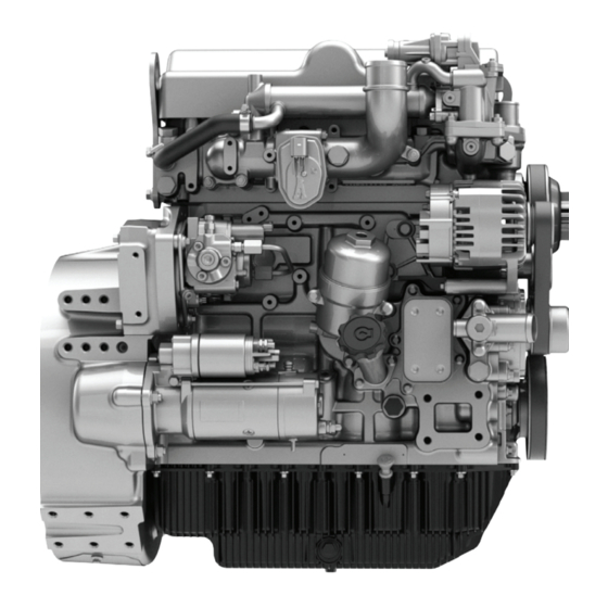
M0108133-04 Product Information Section General Information Product Information Section General Information i08131199 Model View Illustrations The following model views show typical features of the engine. Due to individual applications, your engine may appear different from the illustrations. - Page 24 M0108133-04 Product Information Section Model View Illustrations 904D-E28T Industrial Engine Views Illustration 17 g06561996 Typical example (1) Engine harness interface (5) Oil filter assembly (9) Starting motor (2) NOx Reduction System (NRS) valve (6) Oil filler (lower) (10) High-pressure fuel pump...
- Page 25 M0108133-04 Product Information Section Model View Illustrations Illustration 18 g06559846 Typical example (11) Rear lifting eyes (15) Electronic Control Module (ECM), (19) Fan drive pulley (12) Actuator for turbocharger location for transportation only (20) Drive belt (13) Turbocharger (16) Adjuster for drive belt (21) Coolant outlet (14) Air intake from air cleaner (17) Coolant pump pulley...
- Page 26 M0108133-04 Product Information Section Model View Illustrations 904D-E36TA Industrial Engine Views Illustration 19 g06480143 Typical example (1) Engine harness interface (5) Oil filter assembly (9) Starting motor (2) NOx Reduction System (NRS) valve (6) Oil filler (lower) (10) High-pressure fuel pump (3) Air intake from air charge cooler (7) Oil gauge (Dipstick) (4) Alternator...
- Page 27 M0108133-04 Product Information Section Model View Illustrations Illustration 20 g06480156 Typical example (11) Front lifting eye (16) Electronic Control Module (ECM), (20) Fan drive pulley (12) Rear lifting eyes location for transportation only (21) Drive belt (13) Actuator for turbocharger (17) Adjuster for drive belt (22) Coolant outlet (14) Turbocharger...
- Page 28 Product Description 904D-E28T Industrial Engine The Perkins 904D-E28T industrial engine is a single turbocharged engine with an engine prefix of FE. Note: The front end of the engine is opposite the flywheel end of the engine. The left and the right sides of the engine are determined from the flywheel end.
- Page 29 The engine operating conditions are monitored. The Electronic Control Module (ECM) controls the The Perkins 904D-E36TA industrial engine is a single response of the engine to these conditions and to the turbocharged, air to air charge cooled engine with an demands of the operator.
- Page 30 Aftermarket Products and Perkins Diagnostics” topic (Operation Section). Engines Engine Cooling and Lubrication Perkins does not warrant the quality or performance of non-Perkins fluids and filters. The cooling system and lubrication system consists of the following components: When auxiliary devices, accessories, or consumables (filters, additives, catalysts) which are •...
-
Page 31: Product Identification Information
Emissions Certification Film Illustration 24 g06505322 Typical example (1) Engine serial number plate location Perkins engines are identified by an engine serial number. An example of an engine number is FT*****U000001D. ***** The list number for the engine Type of engine... - Page 32 M0108133-04 Product Information Section Reference Information The engine emission label is typically installed on the flywheel housing at Position (X). An extra engine emission label may be supplied loose. i07989955 Reference Information Information for the following items may be needed to order parts.
-
Page 33: Operation Section
Only load the eyebolts and the brackets under ten- sion. Remember that the capacity of an eyebolt is Consult your Perkins dealer for information regarding less as the angle between the supporting members fixtures for correct engine lifting. - Page 34 4. Remove the drive belt from the engine. Sealed Coolant System Perkins are not responsible for damage which may Ensure that the cooling system is filled with Perkins occur when an engine is in storage after a period in ELC, or an antifreeze that meets “ASTM D6210”...
-
Page 35: Features And Controls
M0108133-04 Operation Section Features and Controls Features and Controls Intake manifold pressure – The intake manifold pressure sensor checks the rated pressure in the engine manifold. i07797317 Fuel rail pressure – The fuel rail pressure sensor Alarms and Shutoffs measures the high pressure or low pressure in the fuel rail. - Page 36 Determine and correct the cause of any significant procedures: change in the readings. Consult your Perkins dealer or your Perkins distributor for assistance. 1. Reduce the load on the engine. Some engine applications are equipped with 2.
- Page 37 M0108133-04 Operation Section Sensors and Electrical Components Indicator Lamps • Shutdown lamp • Warning lamp • Low oil pressure lamp • Wait to start lamp (Glow plug warning lamp) For information, refer to this manual, “Monitoring System (Table for the Indicator Lamps)” for the sequence of operation of the shutdown lamp and the warning lamp.
- Page 38 M0108133-04 Operation Section Sensors and Electrical Components Illustration 29 g06538268 Typical example (1) Engine 47-pin interface connector (5) Control valve for high-pressure fuel (8) Camshaft speed/timing sensor (2) Air inlet temp sensor pump (9) Pre-NRS temperature sensor (3) Coolant temperature sensor (6) Fuel temperature sensor (10) Inlet manifold temperature sensor (4) Alternator...
- Page 39 M0108133-04 Operation Section Sensors and Electrical Components Illustration 30 g06538269 Typical example (12) NRS valve (14) Crankshaft speed/timing sensor (16) Fuel rail pressure sensor (13) Injector 1, 2, 3 and injector 4 (15) Engine oil pressure switch...
- Page 40 M0108133-04 Operation Section Sensors and Electrical Components Off Engine Sensors and Electrical Components Illustration 31 g06481423 Typical example (1) ECM (2) If equipped, Air intake temperature (3) Priming pump sensor (Air Cleaner) (4) Water in fuel switch...
-
Page 41: Engine Diagnostics
The sequence of flashes represents the system diagnostic message. Count the first sequence of flashes in Perkins Electronic Engines have the capability to order to determine the first digit of the flash code. perform a self-diagnostics test. When the system... - Page 42 M0108133-04 Operation Section Engine Operation with Intermittent Diagnostic Codes Note: If the customer has selected “DERATE” and if there is a low oil pressure condition, the Electronic Control Module (ECM) will limit the engine power until the problem is corrected. If the oil pressure is within the normal range, the engine may be operated at the rated speed and load.
-
Page 43: Engine Starting
M0108133-04 Operation Section Engine Starting Engine Starting i08165229 Cold Weather Starting i08158794 Before Starting Engine Do not use aerosol types of starting aids such as Perform the required daily maintenance and other ether. Such use could result in an explosion and periodic maintenance before the engine is started. - Page 44 M0108133-04 Operation Section Starting the Engine 5. Repeat step 2 through step 4 if the engine fails to 3. When the warning light for the glow plugs is start. extinguished, turn the keyswitch to the START position to engage the electric starting motor and Note: After starting, the engine may be held at low crank the engine.
- Page 45 Maintenance Manual, “Battery - Replace” and starting and will damage the electrical system. Testing and Adjusting Manual, “Battery - Test”. For 904D-E28T industrial engines, use a 12 VDC bat- tery source to start the engine. i08165244 For 904D-E36TA industrial engines, ensure that a 12...
- Page 46 M0108133-04 Operation Section After Starting Engine • Allow the engine to idle for 3 to 5 minutes, or allow the engine to idle until the water temperature indicator begins to rise. Check all gauges during the warm-up period. Constant speed engines should be allowed to operate at low idle for 3 minutes before used at operational speed.
-
Page 47: Engine Operation
Emissions regulations require that the value of the emissions be reported to the end user. For the 904D-E28T engine, 831.2 g/kWh was determined to be the CO value during the EU type approval process. - Page 48 Fuel Conservation Practices The efficiency of the engine can affect the fuel economy. Perkins design and technology in manufacturing provides maximum fuel efficiency in all applications. Follow the recommended procedures to attain optimum performance for the life of the engine.
-
Page 49: Cold Weather Operation
Perkins Diesel Engines can operate effectively in start. cold weather. During cold weather, the starting and the operation of the diesel engine depends on the •... - Page 50 A block heater can be 120 V ac temperature is 80° C (176° F) minimum. Carbon 600W or 220 V ac 550W. Consult your Perkins dealer deposit on the valve stems will be kept at a minimum.
- Page 51 This return ensures that coolant flows around the engine Perkins recommends a warning device for the inlet under cold operating conditions. The water manifold temperature and/or the installation of an temperature regulator begins to open when the inlet air temperature gauge.
- Page 52 M0108133-04 Operation Section Fuel Related Components in Cold Weather Be aware of these properties when diesel fuel is Drain the water and sediment from any fuel storage purchased. Consider the average ambient air tank at the following intervals: weekly, service temperature for the engines application.
-
Page 53: Engine Stopping
M0108133-04 Operation Section Engine Stopping Engine Stopping i07797387 After Stopping Engine i07797382 Stopping the Engine Note: Before you check the engine oil, do not operate the engine. Wait for at least 30 minutes after the engine has stopped to allow the engine oil to return to the oil pan. - Page 54 M0108133-04 Operation Section After Stopping Engine • Allow the engine to cool. Check the coolant level. • Check the coolant for correct antifreeze protection and the correct corrosion protection. Add the correct coolant/water mixture, if necessary. • Perform all required periodic maintenance on all driven equipment.
-
Page 55: Maintenance Section
M0108133-04 Maintenance Section Refill Capacities Maintenance Section Table 5 904D-E28T Industrial Engine Refill Capacities Refill Capacities Compartment or System Capacity Engine Only 3.9 L (1.03038 US gal) i08134372 External System Per OEM Refill Capacities The External System includes a radiator or an expansion tank with the following components: heat exchanger and piping. - Page 56 The fuel must meet the minimum requirements that are stated in table 7 . NOTICE The footnotes are a key part of the Perkins Specifica- tion for Distillate Diesel Fuel Table. Read ALL of the footnotes. Table 7...
- Page 57 M0108133-04 Maintenance Section General Fuel Information (Table 7, contd) Distillation °C 10% at 282 °C (539.6 °F) “D86” “ISO 3405” maximum 90% at 360 °C (680 °F) maximum Density at 15 °C (59 °F) Kg / M 800 minimum and 860 No equivalent test “ISO 3675”...
- Page 58 The viscosity of the fuel is significant because fuel NOTICE serves as a lubricant for the fuel system components. Operating with fuels that do not meet the Perkins rec- Fuel must have sufficient viscosity to lubricate the ommendations can cause the following effects: Start-...
- Page 59 Since jet fuel specifications do not mention cetane requirements, Diesel engines have an ability to burn wide variety of Perkins recommends that a fuel sample is taken to fuels. Below is a list of typically encountered fuel determine the cetane number.
- Page 60 Protection Agency (EPA) and European Certification viscosity at the fuel injection pump. Perkins fuels. Perkins does not certify engines on any other recommends that the actual viscosity of the fuel, be fuel. The user of the engine has the responsibility of measured to determine if a fuel cooler is needed.
- Page 61 Rancimant test), and sediment (“ISO12937”). For standby generator sets • Perkins recommends the use of oil analysis to oxidation stability of biodiesel blend must be 20 hours check the quality of the engine oil if biodiesel fuel or more as per “EN15751”.
- Page 62 Group 2 for detail and conditions of use of the If biodiesel or biodiesel blends of fuel are to be used, aviation kerosene fuels. Perkins require the use of Perkins fuel cleaner. For more information on the use of biodiesel and biodiesel blends refer to “Biodiesel Fuel”.
- Page 63 Biomass to liquid (BTL), Gas to liquid (GTL) and Coal • Perkins recommends the use of bulk fuel filter / to liquid (CTL). Hydrotreating of vegetable oils and coalescer units which clean the fuel of both...
- Page 64 M0108133-04 Maintenance Section Fluid Recommendations Table 8 NOTICE If the engine is to be stored in, or shipped to an area Acceptable Water with below freezing temperatures, the cooling system Property Maximum Limit must be either protected to the lowest outside tem- perature or drained completely to prevent damage.
- Page 65 Refer to Table 9 and refer to table 10 . Coolant Recommendations Table 9 The following three glycol-based coolants are Ethylene Glycol recommended for use in Perkins diesel engines: Concentration Freeze Protection Preferred – Perkins ELC −36 °C (−33 °F) 50 Percent −51 °C (−60 °F)
- Page 66 Cleaning agents agents with low amounts of nitrite. Perkins ELC has are only required if the system has been been formulated with the correct amount of these...
- Page 67 M0108133-04 Maintenance Section Fluid Recommendations 9. Fill the cooling system with the Perkins Premixed NOTICE ELC. Care must be taken to ensure that all fluids are con- tained during performance of inspection, mainte- ELC Cooling System Contamination nance, testing, adjusting and the repair of the product.
- Page 68 X is the amount of SCA that is required. manufacturer and are compatible with coolant. Table 15 is an example for using the equation that is Perkins engine cooling systems should be tested at in Table 14 . 250 hour intervals for the concentration of SCA.
- Page 69 7. Fill the system with new coolant. “EMA Recommended Guideline on Diesel Engine Oil”. In addition to Perkins definitions, there are other i08153799 definitions that will be of assistance in purchasing lubricants. Recommended oil viscosities can be Fluid Recommendations found in this publication, “Fluid Recommendations/...
- Page 70 Lubricant Viscosity Recommendations Aftermarket Oil Additives for Direct Injection (DI) Diesel Engines Perkins does not recommend the use of aftermarket additives in oil. It is not necessary to use aftermarket The correct SAE viscosity grade of oil is determined additives to achieve the engines maximum service by the minimum ambient temperature during cold life or rated performance.
- Page 71 M0108133-04 Maintenance Section Engine Oil Specification • The Oil Condition Analysis determines the loss of the oils lubricating properties. An infrared analysis is used to compare the properties of new oil to the properties of the used oil sample. This analysis allows technicians to determine the amount of deterioration of the oil during use.
-
Page 72: Maintenance Recommendations
Consult the OEM of the equip- To relieve the pressure from the coolant system, turn ment or your Perkins dealer regarding welding on a chassis frame or rail. off the engine. Allow the cooling system pressure cap to cool. - Page 73 M0108133-04 Maintenance Section Welding on Engines with Electronic Controls 1. Stop the engine. Turn the switched power to the OFF position. 2. Ensure that the fuel supply to the engine is turned off. 3. Disconnect the negative battery cable from the battery.
- Page 74 • Failure to use recommended fuel, lubricants, and Refer to the standards for the engine or consult your coolant/antifreeze Perkins distributor to determine if the engine is operating within the defined parameters. Severe service operation can accelerate component wear. Engines that operate under severe conditions...
-
Page 75: Maintenance Interval Schedule
M0108133-04 Maintenance Section Maintenance Interval Schedule “ Water Pump - Inspect“..... 101 i08159141 Maintenance Interval Schedule Every 2000 Service Hours “... -
Page 76: Battery - Replace
Aftercooler Core - Clean/Test Alternator - Inspect (Air-To-Air Aftercooler) Perkins recommends a scheduled inspection of the alternator. Inspect the alternator for loose The air-to-air aftercooler is OEM installed in many connections and correct battery charging. Check the applications. Please refer to the OEM specifications ammeter (if equipped) during engine operation in for information that is related to the aftercooler. -
Page 77: Battery Or Battery Cable - Disconnect
M0108133-04 Maintenance Section Battery Electrolyte Level - Check The battery cables or the batteries should not be All lead-acid batteries contain sulfuric acid which can burn the skin and clothing. Always wear a removed with the battery cover in place. The bat- face shield and protective clothing when working tery cover should be removed before any servic- on or near batteries. -
Page 78: Belt - Inspect
M0108133-04 Maintenance Section Belt - Inspect 4. Clean all disconnected connection and battery • More than one section of the belt is displaced in one rib of a maximum length of 50.8 mm (2 inch). terminals. 5. Use a fine grade of sandpaper to clean the To replace the belt, refer to Disassembly and Assembly, “Alternator Belt - Remove and Install”. -
Page 79: Coolant (Commercial Heavy-Duty) - Change
M0108133-04 Maintenance Section Coolant (Commercial Heavy-Duty) - Change • The fuel has entered the cooling system and the coolant is contaminated. NOTICE When any servicing or repair of the engine cooling system is performed, the procedure must be per- formed with the engine on level ground. Level ground will allow you to check accurately the coolant level. - Page 80 This operation will suitable cleaning agent to remove any debris. allow any air in the system to be purged. Decrease Refer to your Perkins dealer or distributor for the engine speed to low idle. Stop the engine. suitable cleaning agents.
- Page 81 To open the cooling system filler cap, suitable cleaning agent to remove any debris. stop the engine and wait until the cooling system Refer to your Perkins dealer or distributor for components are cool. Loosen the cooling system suitable cleaning agents.
-
Page 82: Coolant (Elc) - Change
M0108133-04 Maintenance Section Coolant (ELC) - Change 3. Fill the cooling system with clean water and install 4. Clean the cooling system filler cap. Inspect the the cooling system filler cap. gasket that is on the cooling system filler cap. If the gasket that is on the cooling system filler cap is 4. - Page 83 2. Start and run the engine at low idle. Increase the engine rpm to high idle. Operate the engine to For information regarding the disposal and the recycling of used coolant, consult your Perkins dealer open the engine thermostat. An open thermostat or Perkins distributor.
-
Page 84: Coolant Level - Check
M0108133-04 Maintenance Section Coolant Level - Check 4. Clean the cooling system filler cap. Inspect the gasket that is on the cooling system filler cap. If the gasket that is on the cooling system filler cap is damaged, discard the old cooling system filler cap and install a new cooling system filler cap. -
Page 85: Engine - Clean
Note: The air filter system may not have been Steam cleaning the engine will remove accumulated provided by Perkins. The procedure that follows, is oil and grease. A clean engine provides the following for a typical air filter system. Refer to the OEM benefits: information for the correct procedure. -
Page 86: Engine Air Cleaner Service Indicator - Inspect
M0108133-04 Maintenance Section Engine Air Cleaner Service Indicator - Inspect 6. Install end cover (4) to air cleaner body (2) and secure end cover. If necessary, reset the air service indicator, refer to this Operation and Maintenance Manual, Engine Air Cleaner Service Indicator - Inspect for more information. -
Page 87: Engine Air Precleaner - Check/Clean
Any engine mount that shows deterioration should be replaced. Refer to the OEM information for the recommended torques. When the engine mounts are supplied by Perkins the maintenance procedure will be supplied in the Disassembly and Assembly manual for your engine. - Page 88 M0108133-04 Maintenance Section Engine Oil Level - Check Before Operating the Engine 4. If necessary, drain a small quantity of oil from the crankcase to reduce the oil level. The oil level needs to be between the mark (L) and the mark (H) before operating the engine.
-
Page 89: Engine Oil Sample - Obtain
Do not allow hot oil or hot components to valve is positioned on the cylinder block. contact the skin. Perkins recommends using a sampling valve in order to obtain oil samples. The quality and the consistency of the samples are better when a sampling valve is NOTICE used. - Page 90 24 N·m (212 lb in). If the engine is operated in severe service conditions, Draining the Engine Lubricating Oil Perkins recommends the use of engine oil sampling. Refer to this Operation and Maintenance Manual, From an Oil Pan Equipped With a Engine Oil sample - Obtain for more information.
- Page 91 M0108133-04 Maintenance Section Engine Oil and Filter - Change Illustration 50 g06511911 Typical example of an engine oil pan with a balancer 1. Place a suitable container below oil drain plug (1) and oil drain plug (5). 2. Remove oil drain plug (1) and oil drain plug (5) from engine oil pan (3) and allow the oil to drain into the container for storage or disposal.
- Page 92 M0108133-04 Maintenance Section Engine Oil and Filter - Change 5. Tighten oil drain plug (1) and oil drain plug (5) to a 5. Tighten cap (1) to a torque of 24 N·m (212 lb in) torque of 24 N·m (212 lb in). Remove container Fill the Oil Pan below oil drain plug (1) and oil drain plug (5).
-
Page 93: Fuel System - Prime
M0108133-04 Maintenance Section Fuel System - Prime Electric Fuel Priming Pump 2. Fill the oil pan with the correct amount of new engine lubricating oil. Refer to this Operation and Use the following procedure to remove air from the Maintenance Manual, “Refill Capacities” for more fuel system: information on refill capacities. -
Page 94: Fuel System Primary Filter (Water Separator)
M0108133-04 Maintenance Section Fuel System Primary Filter (Water Separator) Element - Replace If the engine will not start, refer to Troubleshooting, “Engine Cranks but will not Start”. i07989873 Fuel System Primary Filter (Water Separator Element - Replace Fuel leaked or spilled onto hot surfaces or electri- cal components can cause a fire. -
Page 95: Fuel System Primary Filter/Water Separator - Drain
M0108133-04 Maintenance Section Fuel System Primary Filter/Water Separator - Drain 1. After repositioning the self-venting drain up, locate the thread in the new filter element (6) onto the thread (7). Spin on the filter element and tighten the drain valve (2) securely. 2. -
Page 96: Fuel System Secondary Filter - Replace
M0108133-04 Maintenance Section Fuel System Secondary Filter - Replace 2. Ensure that the outer body of the filter assembly is Refer to Systems Operation, Testing, and Adjusting, “Cleanliness of Fuel System clean and free from dirt. Components” for detailed information on the standards of cleanliness that must be observed during ALL work on the fuel system. -
Page 97: Fuel Tank Water And Sediment - Drain
M0108133-04 Maintenance Section Fuel Tank Water and Sediment - Drain 3. Do not use a tool to install the filter assembly. Tighten the assembly by hand. Install the filter bowl (2). Turn the filter bowl clockwise until the filter bowl locks into position against the stops. 4. -
Page 98: Hoses And Clamps - Inspect/Replace
M0108133-04 Maintenance Section Hoses and Clamps - Inspect/Replace Check the fuel daily. Allow five minutes after the fuel • Cracking tank has been filled before draining water and • Softness sediment from the fuel tank. Fill the fuel tank after operating the engine in order to •... -
Page 99: Starting Motor - Inspect
Refer to the Systems Operation, Testing and Adjusting Manual, “Electric Starting System - Test” for more information on the checking procedure and for specifications consult your Perkins dealer or your Perkins distributor for assistance. Illustration 61 g06536519... -
Page 100: Walk-Around Inspection
M0108133-04 Maintenance Section Walk-Around Inspection i07926235 Walk-Around Inspection Inspect the Engine for Leaks and for Loose Connections A walk-around inspection should only take a few minutes. When the time is taken to perform these checks, costly repairs and accidents can be avoided. For maximum engine service life, make a thorough inspection of the engine compartment before starting the engine. -
Page 101: Water Pump - Inspect
M0108133-04 Maintenance Section Water Pump - Inspect • Ensure that the areas around the rotating parts are • Disconnect any battery chargers that are not clear. protected against the current drain of the starting motor. Check the condition and the electrolyte •... -
Page 102: Warranty Section
Emissions Warranty. For a full warranty statement contact your Perkins dealer or your Perkins distributor. For customers that have a valid user name and password, for perkins. com. Login then go to TIPSS, and the warranty information can be accessed. -
Page 103: Reference Information Section
M0108133-04 Reference Information Section Reference Materials Reference Information Section Reference Materials i05204675 Maintenance Log Table 17 Engine Model Customer Identifier Arrangement Number Serial Number Service Quantity Of Service Item Date Authorization Hours Fuel (continued) - Page 104 Contact your local Perkins Distributor Reference Material now and the distributor can provide you with a quote in minutes. You can locate your nearest Perkins (Extended Service Contract) Distributor by visiting: www.perkins.com Extended Service Contracts - purchased in minutes, NOTICE protected for years.
-
Page 105: Index
M0108133-04 Index Section Index After Starting Engine ........45 Diagnostic Flash Code Retrieval..... 41 After Stopping Engine ........53 Diagnostic Lamp..........41 Aftercooler Core - Clean/Test (Air-To-Air Driven Equipment - Check ......84 Aftercooler) ............ 76 Aftercooler Core - Inspect ....... 76 Alarms and Shutoffs ........ - Page 106 Install the Element ........97 Model View Illustrations ........23 Remove the Element ........96 904D-E28T Industrial Engine Views.... 24 Fuel Tank Water and Sediment - Drain ... 97 904D-E36TA Industrial Engine Views ..26 Drain the Water and the Sediment ....97 Loose or Off Engine Components ....
- Page 107 Atmospheres) ..........44 Serial Number Plate........31 Stopping the Engine ........53 Product Description ......... 28 System Pressure Release....... 72 904D-E28T Industrial Engine ...... 28 Coolant System ........... 72 904D-E36TA Engine........29 Engine Oil ............ 72 Aftermarket Products and Perkins Fuel System..........
- Page 109 Product and Dealer Information Note: For product identification plate locations, see the section “Product Identification Information” in the Operation and Maintenance Manual. Delivery Date: Product Information Model: Product Identification Number: Engine Serial Number: Transmission Serial Number: Generator Serial Number: Attachment Serial Numbers: Attachment Information: Customer Equipment Number: Dealer Equipment Number:...
- Page 110 M0108133 ©2021 Perkins Engines Company Limited All Rights Reserved January 2021...
Need help?
Do you have a question about the 904D-E28T and is the answer not in the manual?
Questions and answers